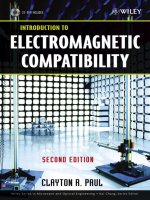
introduction to electromagnetic compatibility (wiley series in microwave and optical engineering)
Bạn đang xem bản rút gọn của tài liệu. Xem và tải ngay bản đầy đủ của tài liệu tại đây (14.32 MB, 1,013 trang )
Introduction to
Electromagnetic
Compatibility
Second Edition
CLAYTON R. PAUL
Department of Electrical and Computer Engineering, School of Engineering,
Mercer University, Macon, Georgia and Emeritus Professor of Electrical
Engineering, University of Kentucky, Lexington, Kentucky
A JOHN WILEY & SONS, INC. PUBLICATION
Introduction to
Electromagnetic
Compatibility
Second Edition
Introduction to
Electromagnetic
Compatibility
Second Edition
CLAYTON R. PAUL
Department of Electrical and Computer Engineering, School of Engineering,
Mercer University, Macon, Georgia and Emeritus Professor of Electrical
Engineering, University of Kentucky, Lexington, Kentucky
A JOHN WILEY & SONS, INC. PUBLICATION
This book is printed on acid-free paper. 1
Copyright # 2006 by John Wiley & Sons, Inc. All rights reserved.
Published by John Wiley & Sons, Inc., Hoboken, New Jersey.
Published simultaneously in Canada.
No part of this publication may be reproduced, stored in a retrieval system, or transmitted in any form or
by any means, electronic, mechanical, photocopying, recording, scanning, or otherwise, except as per-
mitted under Section 107 or 108 of the 1976 United States Copyright Act, without either the prior
written permission of the Publisher, or authorization through payment of the appropriate per-copy fee
to the Copyright Clearance Center, Inc., 222 Rosewood Drive, Danvers, MA 01923, 978-750-8400, fax
978-646-8600, or on the web at www.copyright.com. Requests to the Publisher for permission should
be addressed to the Permissions Department, John Wiley & Sons, Inc., 111 River Street, Hoboken, NJ
07030, (201) 748-6011, fax (201) 748-6008.
Limit of Liability/Disclaimer of Warranty: While the publisher and author have used their best efforts in
preparing this book, they make no representations or warranties with respect to the accuracy or complete-
ness of the contents of this book and specifically disclaim any implied warranties of merchantability or
fitness for a particular purpose. No warranty may be created or extended by sales representatives or
written sales materials. The advice and strategies contained herein may not be suitable for your situation.
You should consult with a professional where appropriate. Neither the publisher nor author shall be liable
for any loss of profit or any other commercial damages, including but not limited to special, incidental,
consequential, or other damages.
For general information on our other products and services please contact our Customer Care Department
within the U.S. at 877-762-2974, outside the U.S. at 317-572-3993 or fax 317-572-4002.
Wiley also publishes its books in a variety of electronic formats. Some content that appears in print,
however, may not be available in electronic format.
Library of Congress Cataloging-in-Publication Data:
Paul, Clayton R.
Introduction to electromagnetic compatibility / Clayton R. Paul 2nd ed.
p. cm.
“Wiley-Interscience.”
Includes bibliographical references and index.
ISBN-13: 978-0-471-75500-5 (alk. paper)
ISBN-10: 0-471-75500-1 (alk. paper)
1. Electromagnetic compatibility. 2. Electronic circuits Noise. 3. Digital electronics. 4.
Shielding (Electricity) I. Title.
TK7867.2.P38 2006
621.382
0
24 dc22
2005049400
Printed in the United States of America
10987654321
This textbook is dedicated to
The humane and compassionate treatment of animals
“For every difficult problem there is always a simple answer and most of them
are wrong.”
“When you can measure what you are speaking about and express it in numbers
you know something about it; but when you cannot measure it, when you cannot
express it in numbers your knowledge is of meagre and unsatisfactory kind; it may
be the beginning of knowledge but you have scarcely progressed in your thoughts
to the stage of science whatever the matter may be.”
Lord Kelvin
Contents
Contents
Preface xvii
1 Introduction to Electromagnetic Compatibility (EMC) 1
1.1 Aspects of EMC 3
1.2 History of EMC 10
1.3 Examples 12
1.4 Electrical Dimensions and Waves 14
1.5 Decibels and Common EMC Units 23
1.5.1 Power Loss in Cables 32
1.5.2 Signal Source Specification 37
Problems 43
References 48
2 EMC Requirements for Electronic Systems 49
2.1 Governmental Requirements 50
2.1.1 Requirements for Commercial Products Marketed
in the United States 50
2.1.2 Requirements for Commercial Products Marketed
outside the United States 55
2.1.3 Requirements for Military Products Marketed in the
United States 60
2.1.4 Measurement of Emissions for Verification of Compliance 62
2.1.4.1 Radiated Emissions 64
2.1.4.2 Conducted Emissions 67
2.1.5 Typical Product Emissions 72
2.1.6 A Simple Example to Illustrate the Difficulty in Meeting
the Regulatory Limits 78
vii
2.2 Additional Product Requirements 79
2.2.1 Radiated Susceptibility (Immunity) 81
2.2.2 Conducted Susceptibility (Immunity) 81
2.2.3 Electrostatic Discharge (ESD) 81
2.2.4 Requirements for Commercial Aircraft 82
2.2.5 Requirements for Commercial Vehicles 82
2.3 Design Constraints for Products 82
2.4 Advantages of EMC Design 84
Problems 86
References 89
3 Signal Spectra—the Relationship between the Time Domain and
the Frequency Domain 91
3.1 Periodic Signals 91
3.1.1 The Fourier Series Representation of Periodic Signals 94
3.1.2 Response of Linear Systems to Periodic Input Signals 104
3.1.3 Important Computational Techniques 111
3.2 Spectra of Digital Waveforms 118
3.2.1 The Spectrum of Trapezoidal (Clock) Waveforms 118
3.2.2 Spectral Bounds for Trapezoidal Waveforms 122
3.2.2.1 Effect of Rise/Falltime on Spectral Content 123
3.2.2.2 Bandwidth of Digital Waveforms 132
3.2.2.3 Effect of Repetition Rate and Duty Cycle 136
3.2.2.4 Effect of Ringing (Undershoot/Overshoot) 137
3.2.3 Use of Spectral Bounds in Computing Bounds on the
Output Spectrum of a Linear System 140
3.3 Spectrum Analyzers 142
3.3.1 Basic Principles 142
3.3.2 Peak versus Quasi-Peak versus Average 146
3.4 Representation of Nonperiodic Waveforms 148
3.4.1 The Fourier Transform 148
3.4.2 Response of Linear Systems to Nonperiodic Inputs 151
3.5 Representation of Random (Data) Signals 151
3.6 Use of SPICE (PSPICE) In Fourier Analysis 155
Problems 167
References 175
4 Transmission Lines and Signal Integrity 177
4.1 The Transmission-Line Equations 181
4.2 The Per-Unit-Length Parameters 184
4.2.1 Wire-Type Structures 186
viii CONTENTS
4.2.2 Printed Circuit Board (PCB) Structures 199
4.3 The Time-Domain Solution 204
4.3.1 Graphical Solutions 204
4.3.2 The SPICE Model 218
4.4 High-Speed Digital Interconnects and Signal Integrity 225
4.4.1 Effect of Terminations on the Line Waveforms 230
4.4.1.1 Effect of Capacitive Terminations 233
4.4.1.2 Effect of Inductive Terminations 236
4.4.2 Matching Schemes for Signal Integrity 238
4.4.3 When Does the Line Not Matter, i.e., When is Matching
Not Required? 244
4.4.4 Effects of Line Discontinuities 247
4.5 Sinusoidal Excitation of the Line and the Phasor Solution 260
4.5.1 Voltage and Current as Functions of Position 261
4.5.2 Power Flow 269
4.5.3 Inclusion of Losses 270
4.5.4 Effect of Losses on Signal Integrity 273
4.6 Lumped-Circuit Approximate Models 283
Problems 287
References 297
5 Nonideal Behavior of Components 299
5.1 Wires 300
5.1.1 Resistance and Internal Inductance of Wires 304
5.1.2 External Inductance and Capacitance of Parall el Wires 308
5.1.3 Lumped Equivalent Circuits of Parallel Wires 309
5.2 Printed Circuit Board (PCB) Lands 312
5.3 Effect of Component Leads 315
5.4 Resistors 317
5.5 Capacitors 325
5.6 Inductors 336
5.7 Ferromagnetic Materials—Saturation and Frequency Response 340
5.8 Ferrite Beads 343
5.9 Common-Mode Chokes 346
5.10 Electromechanical Devices 352
5.10.1 DC Motors 352
5.10.2 Stepper Motors 355
5.10.3 AC Motors 355
5.10.4 Solenoids 356
5.11 Digital Circuit Devices 357
5.12 Effect of Component Variability 358
5.13 Mechanical Switches 359
5.13.1 Arcing at Switch Contacts 360
CONTENTS ix
5.13.2 The Showering Arc 363
5.13.3 Arc Suppression 364
Problems 369
References 375
6 Conducted Emissions and Susceptibility 377
6.1 Measurement of Conducted Emissions 378
6.1.1 The Line Impedance Stabilization Network (LISN) 379
6.1.2 Common- and Differential-Mode Currents Again 381
6.2 Power Supply Filters 385
6.2.1 Basic Properties of Filters 385
6.2.2 A Generic Power Supply Filter Topology 388
6.2.3 Effect of Filter Elements on Common- and
Differential-Mode Currents 390
6.2.4 Separation of Conducted Emissions into Common-
and Differential-Mode Components for
Diagnostic Purposes 396
6.3 Power Supplies 401
6.3.1 Linear Power Supplies 405
6.3.2 Switched-Mode Power Supplies (SMPS) 406
6.3.3 Effect of Power Supply Components on Conducted
Emissions 409
6.4 Power Supply and Filter Placement 414
6.5 Conducted Susceptibility 416
Problems 416
References 419
7 Antennas 421
7.1 Elemental Dipole Antennas 421
7.1.1 The Electric (Hertzian) Dipole 422
7.1.2 The Magnetic Dipole (Loop) 426
7.2 The Half-Wave Dipole and Quarter-Wave Monopole Antennas 429
7.3 Antenna Arrays 440
7.4 Characterization of Antennas 448
7.4.1 Directivity and Gain 448
7.4.2 Effective Aperture 454
7.4.3 Antenna Factor 456
7.4.4 Effects of Balancing and Baluns 460
7.4.5 Impedance Matching and the Use of Pads 463
7.5 The Friis Transmission Equation 466
7.6 Effects of Reflections 470
7.6.1 The Method of Images 470
x CONTENTS
7.6.2 Normal Incidence of Uniform Plane Waves on Plane,
Material Boundaries 470
7.6.3 Multipath Effects 479
7.7 Broadband Measurment Antennas 486
7.7.1 The Biconical Antenna 487
7.7.2 The Log-Periodic Antenna 490
Problems 494
References 501
8 Radiated Emissions and Susceptibility 503
8.1 Simple Emission Models for Wires and PCB Lands 504
8.1.1 Differential-Mode versus Common-Mode Currents 504
8.1.2 Differential-Mode Current Emission Model 509
8.1.3 Common-Mode Current Emission Model 514
8.1.4 Current Probes 518
8.1.5 Experimental Results 523
8.2 Simple Susceptibility Models for Wires and PCB Lands 533
8.2.1 Experimental Results 544
8.2.2 Shielded Cables and Surface Transfer Impedance 546
Problems 550
References 556
9 Crosstalk 559
9.1 Three-Conductor Transmission Lines and Crosstalk 560
9.2 The Transmission-Line Equations for Lossless Lines 564
9.3 The Per-Unit-Length Parameters 567
9.3.1 Homogeneous versus Inhomogeneous Media 568
9.3.2 Wide-Separation Approximations for Wires 570
9.3.3 Numerical Methods for Other Structures 580
9.3.3.1 Wires with Dielectric Insulations
(Ribbon Cables) 586
9.3.3.2 Rectangular Cross-Section Conductors
(PCB Lands) 590
9.4 The Inductive–Capacitive Coupling Approximate Model 595
9.4.1 Frequency-Domain Inductive-Capacitive Coupling
Model 599
9.4.1.1 Inclusion of Losses: Common-Impedance
Coupling 601
9.4.1.2 Experimental Results 604
9.4.2 Time-Domain Inductive–Capacitive Coupling Model 612
9.4.2.1 Inclusion of Losses: Common-Impedance Coupling 616
9.4.2.2 Experimental Results 617
CONTENTS xi
9.5 Lumped-Circuit Approximate Models 624
9.6 An Exact SPICE (PSPICE) Model for Lossless, Coupled Lines 624
9.6.1 Computed versus Experimental Results for Wires 633
9.6.2 Computed versus Experimental Results for PCBs 640
9.7 Shielded Wires 647
9.7.1 Per-Unit-Length Parameters 648
9.7.2 Inductive and Capacitive Coupling 651
9.7.3 Effect of Shield Grounding 658
9.7.4 Effect of Pigtails 667
9.7.5 Effects of Multiple Shields 669
9.7.6 MTL Model Predictions 675
9.8 Twisted Wires 677
9.8.1 Per-Unit-Length Parameters 681
9.8.2 Inductive and Capacitive Coupling 685
9.8.3 Effects of Twist 689
9.8.4 Effects of Balancing 698
Problems 701
References 710
10 Shielding 713
10.1 Shielding Effectiveness 718
10.2 Shielding Effectiveness: Far-Field Sources 721
10.2.1 Exact Solution 721
10.2.2 Approximate Solution 725
10.2.2.1 Reflection Loss 725
10.2.2.2 Absorption Loss 728
10.2.2.3 Multiple-Reflection Loss 729
10.2.2.4 Total Loss 731
10.3 Shielding Effectiveness: Near-Field Sources 735
10.3.1 Near Field versus Far Field 736
10.3.2 Electric Sources 740
10.3.3 Magnetic Sources 740
10.4 Low-Frequency, Magnetic Field Shielding 742
10.5 Effect of Apertures 745
Problems 750
References 751
11 System Design for EMC 753
11.1 Changing the Way We Think about Electrical Phenomena 758
11.1.1 Nonideal Behavior of Components and the
Hidden Schematic 758
11.1.2 “Electrons Do Not Read Schematics” 763
xii CONTENTS
11.1.3 What Do We Mean by the Term “Shielding”? 766
11.2 What Do We Mean by the Term “Ground”? 768
11.2.1 Safety Ground 771
11.2.2 Signal Ground 774
11.2.3 Ground Bounce and Partial Inductance 775
11.2.3.1 Partial Inductance of Wires 781
11.2.3.2 Partial Inductance of PCB Lands 786
11.2.4 Currents Return to Their Source on the Paths of Lowest
Impedance 787
11.2.5 Utilizing Mutual Inductance and Image Planes to Force
Currents to Return on a Desired Path 793
11.2.6 Single-Point Grounding, Multipoint Grounding, and
Hybrid Grounding 796
11.2.7 Ground Loops and Subsystem Decoupling 802
11.3 Printed Circuit Board (PCB) Design 805
11.3.1 Component Selection 805
11.3.2 Component Speed and Placement 806
11.3.3 Cable I/O Placement and Filtering 808
11.3.4 The Important Ground Grid 810
11.3.5 Power Distribution and Decoupling Capacitors 812
11.3.6 Reduction of Loop Ar eas 822
11.3.7 Mixed-Signal PCB Partitioning 823
11.4 System Configuration and Design 827
11.4.1 System Enclosures 827
11.4.2 Power Line Filter Placement 828
11.4.3 Interconnection and Number of Printed
Circuit Boards 829
11.4.4 Internal Cable Routing and Connector Placement 831
11.4.5 PCB and Subsystem Placement 832
11.4.6 PCB and Subsystem Decoupling 832
11.4.7 Motor Noise Suppression 832
11.4.8 Electrostatic Discharge (ESD) 834
11.5 Diagnostic Tools 847
11.5.1 The Concept of Dominant Effect in the Diagnosis of
EMC Problems 850
Problem 856
References 857
Appendix A The Phasor Solution Method 859
A.1 Solving Differential Equations for Their Sinusoidal,
Steady-State Solution 859
CONTENTS xiii
A.2 Solving Electric Circuits for Their Sinusoidal,
Steady-State Response 863
Problems 867
References 869
Appendix B The Electromagnetic Field Equations and Waves 871
B.1 Vector Analysis 872
B.2 Maxwell’s Equations 881
B.2.1 Faraday’s Law 881
B.2.2 Ampere’s Law 892
B.2.3 Gauss’ Laws 898
B.2.4 Conservation of Charge 900
B.2.5 Constitutive Parameters of the Medium 900
B.3 Boundary Conditions 902
B.4 Sinusoidal Steady State 907
B.5 Power Flow 909
B.6 Uniform Plane Waves 909
B.6.1 Lossless Media 912
B.6.2 Lossy Media 918
B.6.3 Power Flow 922
B.6.4 Conductors versus Dielectrics 923
B.6.5 Skin Depth 925
B.7 Static (DC) Electromagnetic Field Relations—
a Special Case 927
B.7.1 Maxwell’s Equations for Static (DC) Fields 927
B.7.1.1 Range of Applicability for
Low-Frequency Fields 928
B.7.2 Two-Dimensional Fields and Laplace’s
Equation 928
Problems 930
References 939
Appendix C Computer Codes for Calculating the Per-Unit-Length
(PUL) Parameters and Crosstalk of Multiconductor
Transmission Lines 941
C.1 WIDESEP.FOR for Computing the PUL
Parameter Matrices of Widely Spaced Wires 942
C.2 RIBBON.FOR for Computing the PUL Parameter
Matrices of Ribbon Cables 947
C.3 PCB.FOR for Computing the PUL Parameter
Matrices of Printed Circuit Boards 949
xiv CONTENTS
C.4 MSTRP.FOR for Computing the PUL Parameter
Matrices of Coupled Microstrip Lines 951
C.5 STRPLINE.FOR for Computing the PUL
Parameter Matrices of Coupled Striplines 952
C.6 SPICEMTL.FOR for Computing a SPICE
(PSPICE) Subcircuit Model of a Lossless,
Multiconductor Transmission Line 954
C.7 SPICELPI.FOR For Computing a SPICE (PSPICE)
Subcircuit of a Lumped-Pi Model of a Lossless,
Multiconductor Transmission Line 956
Appendix D A SPICE (PSPICE) Tutorial 959
D.1 Creating the SPICE or PSPICE Program 960
D.2 Circuit Description 961
D.3 Execution Statements 966
D.4 Output Statements 968
D.5 Examples 970
References 974
Index 975
CONTENTS xv
PREFACE
Preface
This is the second edition of a textbook that was originally published in 1992 and is
intended for a university/college course in electromagnetic compatibility (EMC). It
has also proved to be very beneficial as a reference for industrial professionals
interested in EMC design. The prerequisites are the completion of the basic under-
graduate electrical engineering courses in electric circuit analysis, signals and
systems, electronics, and electromagnetic fields. The text builds on those basic
skills, principles, and concepts and applies them to the design of modern electronic
systems so that these systems will operate compatibly with other electronic systems
and also comply with various governmental regulations on radiated and conducted
electromagnetic emissions. In essence, EMC deals with interference and the
prevention of it through the design of electronic systems.
The subject of EMC is rapidly becoming as important a subdiscipline of electrical
engineering (EE) as other more traditional subjects such as electric circuit analysis
and electronics. One of the first such courses in EMC that was introduced into an
EE undergraduate curriculum was organized in the early 1980s at the University
of Kentucky by the author. It was taught as a senior technical elective and continues
to be taug ht as an elective course there and at the author’s present institution, Mercer
University. The subject is rapidly increasing in importance, due in part to the
increasing use and speeds of digital electronics in today’s mode rn world. It is
currently being offered in a large number of electrical engi neering curricula in
schools in the United States and throughout the world. The number of schools offer-
ing an EMC course will no doubt continue to rapidly increase. The reasons for EMC
having grown in importance at such a rapid pace are due to (1) the increasing speeds
and use of digital electronics in today’s world and (2) the virtual worldwide impo-
sition of governmental limits on the radiated and conducted noise emissions of
digital electronic products. Prior to 1979, the United States did not restrict the elec-
tromagnetic noise emissions of digital electronic products that were to be sold within
its borders. Manufacturers of digita l electronic devices voluntarily imposed their
own limits in order to produce quality products whose electromagnetic emissions
xvii
would not cause interference with other electronic devices. In addition, manufac-
turers tested their products to determine their susceptibility to electromagnetic emis-
sions from other sources so that the product would operate reliably in the intended
environment. In 1979 the U.S. Federal Communications Commission (FCC) pub-
lished a law that placed legal limits on the radiated emissions from and the con-
ducted emissions out the device power cord of all digital devices (devices that
use a clock of 9 kHz or greater and use “digital techniques”) to be sold in the
United States. This transformed what was a voluntary matter into a legal one.
This made it illegal to sell a digital device (no matter how innovative the device)
in the United States unless its noise emissions were below the limits set by the
FCC. Many countries throughout the world, and primarily those of Europe,
already had similar such laws in place. This caused a dras tic change in how compa-
nies producing electronic products design those products. It no longer mattered that
the product had some new and revolutionary use or function; if it did not comply
with these legal limits, it could not be placed on the market!
Since the original publication of this text in 1992, several significant develop-
ments occurred that have dramatically increased the importance of EMC in not
only universities but also across the electronics industry. Countries in Europe
(which represents a major market for electronics produced in the USA) formed
the European Union and imposed even more stringent and pervasive EMC regu-
lations than were in place before the turn of the century. Processing speeds (clock
and data speeds) of digital products have increased at a dramatic rate. In the mid
1980s the clock speeds were on the order of tens of megahertz (MHz). Personal com-
puters are now available with clock frequencies over 3 GHz and that cost under $500
U.S. This has dramatically increased the difficulty of complying with the EMC gov-
ernmental regulations. The combination of lowered costs and higher speeds of
digital devices mean that effective EMC design practices are now much more criti-
cal in order to avoid unnecessary costs of EMC suppression measures that are added
to bring the products into compliance. Frequencies of use even in analog systems are
escalating well into the GHz range, and it is difficult to find a product (including
washing machines, automobil es, etc.) that doesn’t use digital electronics as a
primary factor in that product’s performance. These mandatory governmental
requirements to minimize a digital product’s electromagnetic noise emissions and
the rapidly decr easing costs and product development schedules of those products
mean that all EEs must now be trained in proper EMC design techniques. Electrical
engineers that have not been trained in EMC design will be severely handicapped
when they enter the workplace.
This second edition has been substantially rewritten and revised to reflect the
developments in the field of EMC. Chapters have been repositioned and their
content revised. Chapter 1, Introduction to Electromagnetic Compatibility (EMC),
has remained essentially the same as in the first edition. An important discussion
of the concept of an electromagnet ic wave has been added to that chapter.
Chapter 2, EMC Requirements for Electronic Systems, although retaining its pre-
vious place in the outline, has been substantially revised to reflect the rather substan-
tial revisions of the governmental regulatory requirements that have occurred in the
xviii PREFACE
United States and throughout the world. Chapter 3, Signal Spectra—the Relation-
ship between the Time Domain and the Frequency Domain, was moved from its pre-
vious place as Chapter 7 in the first edition to its present place as Chapter 3. This was
done because the author feels that this topic is one of the—if not the—most im-
portant topic in EMC, and this repositioning is intended to get the reader to begi n
thinking in terms of signal spectra early on. Use of SPICE (simulation program
with integrated circuit emphasis) [PSPICE (personal computer SPICE)] in comput-
ing signal spectra has now been included in that chapter. Chapter 4, Transmission
Lines and Signal Integrity, has been significantly revised. A significant revision of
this chapter is the inclusion of the topic of signal integrity. Some 10 years ago
when this text was originally published, clock and data speeds were in the low
MHz range and hence land lengths on printed circuit boards (PCBs) were inconse-
quential; their electromagnetic effects could generally be ignored. The propagation
delays through the gates were on the order of tens of nanoseconds and dominated the
delay caused by the signal lands. Now, virtually all lands on PCBs must be treated as
transmission lines, or else the product will not function properly. This is a result of
the length of the PCB traces becoming significant portions of a wavelength because
of the dramatic increase in the spectral content of the digital signals. Matching of
these transmission lines is now not an option. Again, use of SPICE (PSPICE) in
the analysis of these interconnect leads has been given greater emphasis in this
chapter. Chapter 5, Nonideal Behavior of Components, has been moved earlier
from its place as Chapter 6 in the previous edition and is retained as a part of the
early discussion of important concepts. It has been revised but contains substantially
the same content and topic areas.
Chapter 6, Conducted Emissions and Susceptibility, is essentially the same as
Chapter 7 of the first edition. In this second edition it appears before the topic of
radiated emissions to reflect the author’s feeling of its proper sequence. Chapter 7,
Antennas, is essentially the same as Chapter 5 in the first edition. Chapter 8,
Radiated Emissions and Susceptibility, is essentially the same as Chapter 8 of the
first edition but has been revi sed. Chapter 9, Crosstalk, has been substantially
revised from its version as Chapter 10 of the first edition. The mathematics has
been considerably simplified. There are three significant revisions in this chapter.
First, the simple inductive –capacitive coupling model for weakly coupled, electri-
cally short lines has been moved earlier in the chapter, and its derivation now is
argued on somewhat intuitive grounds to simplify the discussion. Second, the com-
putation of the per-unit-length parameters is shown using static numerical methods
(method of moments) in a simple fashion in order to familiarize the reader with the
modern numerical methods that are growing in use and importance. FORTRAN pro-
grams are described here and in Appendix C that compute these parameters very
accurately for ribbon cables, PCB land structures, coupled microstrip lines, and
coupled striplines. These FORTRAN codes are contained in a CD that is supplie d
with this textbook. Third, a FORTRAN program that prepares an exact SPICE
(PSPICE) subcircuit model for a coupled transmission line is described, and its
use is illustrated throughout the chapter. It is also supplied on that CD. The import-
ance of this is that the reader can now easily investigate crosstalk on complicated
PREFACE xix
(but realistic) transmission lines on PCBs that have realistic loads such as capacitors,
inductors, transistors, and logic gates, which complicate a hand analysis. This also
introduces the reader to the modern use of computer-aided design (CAD) simulation
methods that are increasing in importance and popularity. Chapter 10, Shielding, is
essentially the same as Chapter 11 of the first editi on. Chapter 12 on elect rostatic
discharge in the first edition has been eliminated as a separate chapter in the
second edition, but its content has been incorporated into the final chapter,
Chapter 11, System Design for EMC (which was the previous Chapter 13 of the
first edition).
The text of that chapter has been virtually rewritten in both content and organi-
zation from its earlier version. It is now organize d into five major topic areas:
Section 11.1, Changing the Way We Think about Electrical Phenomena; Section
11.2, What Do We Mean by the Term “Ground”?; Section 11.3, Printed Circuit
Board (PCB) Design; Section 11.4, System Configuration and Design; and
Section 11.5, Diagnostic Tools. This was done to cause the reader to focus on the
important aspects of EMC design without getting lost in detail. Section 11.5, Diag-
nostic Tools, is new to the text and reflects the author’s view that it is virtually
impossible to design a digital device to pass the regulatory requirements on the
first testing. It is crucially important in this age of low product cost and reduced
development schedules to be able to determine the exact cause of the noncompliance
and to determine how to bring the product into compliance with minimum added
cost and minimum impact on the development schedule. The important concept
of Dominant Effect is critical to the rapid diagnosis of EMC problems and the
demystifying of EMC and is discussed here.
Several append ixes are new to this second edition. Appendix A, The Phasor
Solution Met hod, is a brief review of the important phasor solution of differential
equations and electric circuits: their sinusoidal, steady-state solution. This skill is
the most important and fundamental skill of an electrical engineer. It permeates all
electrical engineering areas, such as circuit analysis, signal analysis, system analysis,
electronic circuit analysis, and electromagnetics. Unless the reader has this important
skill mastered, very little can be gained or understood from this textbook or any other
electrical engineering textbook. Hence this appendix serves as a brief review of this
crucial skill. Appendix B, The Electromagnetic Field Equations and Waves, is a brief
but sufficient review of the important electromagnetic principles and laws. It was
placed in an appendix rather than in the body of the text, as in the first edition, in
order to avoid breaks in the flow of the material. Appendix C, Computer Codes
for Calculating the Per-Unit-Length Parameters and Crosstalk of Multiconductor
Transmission Lines, describes the FORTRAN programs that can be used to model
and predict crosstalk of complex (but representative) transmission lines. These are
also placed on the CD that is supplied with this textbook. Appendix D, A SPICE
(PSPICE) Tutorial, is a brief but sufficient tutorial on the use of the PSPICE
program to model and simulate electric circuits.
This edition of the textbook has emphasized a dramatic increase in the use of
PSPICE to simulate virtually all areas of EMC analysis. Again, this is in line with
the current emphasis on and use of modern CAD tools in EM C. Another sign ificant
xx PREFACE
innovation in this text is the use of worked-out Example Problems and Review Exer-
cises. Detailed worked-out examples are strategically placed after discussion of
major concepts to show the reader how to work important EMC problems. These
are clearly delineated from the text to enable the reader to focus on these
problem-solving skills. In addition, a large number of Review Exercises are included
after discussion of each important topic. The exercises are in the form of a simple
question, and the answer is given. Hence the reader can quickly check his/her
comprehension of the topic immediately after its discussion. Most of the End-of-
Chapter Problems are new and the answer s are given at the end of the problem in
brackets [ ], as was the custom in the first edition.
The Author would like to thank Cadence Design Systems, Inc. for allowing John
Wiley Interscience to distribute OrCAD and MicroSim software with this book.
OrCAD PSPICE version 10 and MicroSim PSPICE version 8 are included in the
CD supplied with this textbook. The reader can therefore immediately install the
programs on his/her personal computer and begin to perform the simulations in
this book.
Many of the author’s colleagues in the EMC industry have had considerable
influence on his way of thinking about EMC and have contributed significantly to
the author’s ability to produce this text. Of primary mention are the insights
gained from and numerous discussions with Mr. Henry Ott, which have significantly
impacted the author’s EMC perspective. The author highly recommends Mr. Ott’s
Website, . It contains links to the latest revisions
of the regulations. But more importantly it contain s numerous highly detailed and
informative tutorial articles and other references on EMC. The author also owes a
significant debt of gratitude for this association with and insights gained from
working with colleagues in the EMC group at IBM Information Products Division
in Lexington, Kentucky (now Lexm ark International) during a sabbatical leave in
1984 and consulting there for some 10 years thereafter. Working with those indivi-
duals on significant EMC problems was the primary reason why this text was
originally published. Primary among those individuals are Mr. Donald R. Bush,
Dr. Keith B. Hardin, and Mr. Stephen G. Parker. The late Mr. Donald R. Bush
was also a personal friend of the author and had a profound influence on the
author, both personally and professionally, for over 30 years. The author would
also like to acknowledge and thank Mr. John Fessler of Lexmark International for
his discussions on the latest governmental regualtions.
C
LAYTON R. PAUL
Macon, Georgia, January 2005
PREFACE
xxi
CHAPTER ONE
Introduction to Electromagnetic
Compatibility (EMC)
Since the early days of radio and telegraph communications, it has been known that a
spark gap generates electromagnetic waves rich in spectral content (frequency com-
ponents) and that these waves can cause interference or noise in various electronic
and electrical devices such as radio receivers and telephone communications.
Numerous other sources of electromagnetic emissions such as lightning, relays,
dc electric motors, and fluorescent lights also generate electromagnetic waves that
are rich in spectral content and can cause interference in those devices. There are
also sources of electromagnetic emissions that contain only a narrow band of fre-
quencies. High-voltage power transmission lines generate electromagnetic emis-
sions at the power frequency [60 Hz; 50 Hz in Europe]. Radio transmitters
transmit desired emissions by encoding information (voice, music, etc.) on a
carrier frequency. Radio receivers intercept these electromagnetic waves, amplify
them, and extract the information that is encoded in the wave. Radar transmitters
also transmit pulses of a single-frequency carrier. As this carrier frequency is
pulsed on and off, these pulses radiate outward from the antenna, strike a target,
and return to the radar antenna. The total transit time of the wave is directly
related to the distance of the target from the radar antenna. The spectral content
of this radar pulse is distributed over a larger band of frequencies around the
carrier than are radio transmissions. Another important and increasingly significant
source of electromagnetic emissions is associated with digital computers in particu-
lar and digital electronic devices in general. These digital devices utilize pulses to
signify a binary number, 0 (off) or 1 (on). Numbers and other symbols are rep-
resented as sequences of these binary digits. The transition time of the pulse from
off to on and vice versa is perhaps the most important factor in determining the spec-
tral content of the pulse. Fast (short) transition times generate a wider range of
1
Introduction to Electromagnetic Compatibility, Second Edition, by Clayton R. Paul
Copyright # 2006 John Wiley & Sons, Inc.
