the ins and outs of focus internet edition
Bạn đang xem bản rút gọn của tài liệu. Xem và tải ngay bản đầy đủ của tài liệu tại đây (2.17 MB, 92 trang )
.
DEPTH
OF
FIELD
LENS-TO-SUBJECT DISTANCE
Focal
Length
0
DEPTH OF FOCUS
LENS-TO-FILM DISTANCE
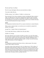
An Alternative Way
to Estimate
Depth-of-Field and
Sharpness
in the Photographic Image
The INs and OUTs of FOCUS
is a book for the
advanced photographer who wishes to take advantage
of today's high performance materials and
lenses.
Mastery over the imaging process is the goal:
Limitations due to diffraction, focal length, f-stop,
curvature of field, and film curl are weighed against
what is possible.
If you have been frustrated by a seeming inability to
consistently obtain super-sharp images, this may be
the book for you. The reader is taken beyond the
traditional concept of depth-of-field to learn how to
control precisely what will (or will not) be recorded
in the image.
This book contains information you have not read in
any other popular book on photography.
LENS
Object
in Exact
Focus
FILM
PLANE
Focus Error
The
Disk
-of-Confusion
The Circle-of-Confusion
Object
of Interest
BLACK
RED
Internet Edition
by Harold M. Merklinger
The INs and OUTs
of FOCUS
An Alternative Way to Estimate
Depth-of-Field and
Sharpness
in the Photographic Image
by
Harold M. Merklinger
Published by the author
Internet Edition
/>Published by the author:
Harold M. Merklinger
P.O. Box 494
Dartmouth, Nova Scotia
Canada, B2Y 3Y8.
v 1.0 1 August 1990
v 1.0.2 1 April 1991
v1.03e 1 April 2002
(Internet edition).
ISBN 0-9695025-0-8
© All commercial rights reserved. This electronic book is the equivalent of
shareware. It may be distributed freely provided it is not altered in any way and
that no fee is charged. The book may be printed (in whole or in part) for private
or educational use only. No part of this book may be reproduced or translated
for compensation without the express written permission of the author. If you
enjoy the book and find it useful, a $5 payment to the author at the address
above will assist with future publications. Postal money orders and Canadian or
US personal cheques work well.
Created in Canada using Adobe Acrobat Distiller, version 3. Note: add 5 to the
book page number to get the page number of the electronic document.
ACKNOWLEDGEMENTS
Dedicated to my wife, Barbara, whose idea it was to buy the computer which
made this book a realistic proposition for a man who canÕt spell or type.
The terms ÒLeicaÓ, ÒM6Ó, ÒSummicronÓ, ÒElmarÓ and ÒDR SummicronÓ are
trademarks of Ernst Leitz Wetzlar GmbH. ÒPROWLERÓ is a trademark of
Fleetwood Industries Canada Ltd. ÒKodakÓ, ÒTechnical PanÓ and ÒKodak
AnastigmatÓ are trademarks of the Eastman Kodak Company. ÒPan FÓ is a
trademark of Ilford Limited (Ciba-Geigy). ÒTessarÓ is a trademark of
Zeiss-Ikon AG.
ii
CONTENTS
Page
CHAPTER 1: Depth-of-Field—The Concept 1
CHAPTER 2: Basic Ideas and Definitions 3
Aside: Using Figure 4 to calculate lens extension for close-ups 11
CHAPTER 3: The Traditional Approach—The Image 13
Near and Far Limits of Depth-of-Field 14
Hyperfocal Distance 14
A Graphical Solution 16
Depth-of-Field Scales 16
Where to Set the Focus 19
Should the size of the Circle-of-Confusion vary with Focal
Length? 20
CHAPTER 4: Is the Traditional Approach the Best Approach? 21
CHAPTER 5: A Different Approach—The Object Field 25
The Disk-of-Confusion 25
Examples 29
Object Field Rules of Thumb 36
Working in the Object Space 38
CHAPTER 6: Convolution—The Blurring of an Image 39
CHAPTER 7: Lenses, Films and Formats 49
Diffraction Limits 49
Depth-of-Focus Considerations 51
Film and Field Curvature 52
Film Formats 53
Depth-of-Focus and Focal Length 55
Poor-Man’s Soft-Focus Lens 58
CHAPTER 8: Focusing Screens—Can you see the Effect? 61
CHAPTER 9: Discussion—Which Method Works? 65
CHAPTER 10: Rules of Thumb 69
CHAPTER 11: Summary 73
CHAPTER 12: Historical Notes and Bibliography 75
Historical Notes 75
Bibliography 78
INDEX 80
ADDENDUM: About the author, the book and the photographs 83
iii
The INs and OUTs of FOCUS
Merklinger:
THE INS AND OUTS OF FOCUSiv
LGK II
1CHAPTER 1: Depth-of-Field—The Concept
CHAPTER 1
Depth-of-Field—The Concept
The concept of depth-of-field derives from the observation that not
all parts of all photographic images need to be perfectly sharp. Indeed, the
physical limitations of lenses, film, and printing media dictate that nothing
will in fact be perfectly sharp. This observation, then, brings us to the
question: how sharp is sharp enough? Once we establish a standard, the
next problem is to discover rules which govern how the standard may be
achieved in practice. In applying these rules we learn that there is usually
a range of distances for which typical objects will be acceptably well
rendered in our photographic image. This range of distances is the
depth-of-field. But sometimes, the photographic art form demands that
certain images be intentionally blurred. A complete guide to photographic
imaging must also help us create a controlled degree of unsharpness. (As
an aside, I often think that photography’s greatest contribution to the
graphic arts is the unsharp image. Prior to the invention of photography,
man tended to paint all images sharply—the way the autofocus human eye
sees them.)
This booklet is intended to explore concepts of photographic image
sharpness and to explain how to control it. After establishing a few
definitions and such, we will examine the traditional approach to the
subject of depth-of-field and discuss the limitations of this theory.
Although almost all books on photography describe this one view of the
subject, it should be understood that other quite valid philosophies are also
possible. And different philosophies on depth-of-field can provide
surprisingly different guidance to the photographer. We will see, for
example, that while the traditional rules tell us we must set our lens to f/56
and focus at 2 meters in one situation, a different philosophy might tell us
to use f/10 and set the focus on infinity. And while the traditional
approach provides us with only pass/fail sharpness criteria, there
nevertheless exist simple ways to give good quantitative estimates of
image smearing effects. Photographic optics, or lenses, of course affect
apparent depth-of-field; we’ll examine a number of interrelationships
between lens characteristics, depth-of-field, and desired results. We’ll
Merklinger:
THE INS AND OUTS OF FOCUS
22
also ask the question: Is what you see through your single-lens-reflex
camera viewfinder what you get in your picture?
It will be assumed throughout that the reader is familiar with basic
photographic principles. You need not have read and understood the
many existing treatments of depth-of-field, but I hope you understand how
to focus and set the lens opening of an adjustable camera. If you have
previously been frustrated with poor definition in your photographs, that
experience will be a definite plus: my motivation in writing this booklet
was years of trying to understand unacceptable results even though I
followed the rules. (I also experienced unexpected successes sometimes
when I broke the rules.) The booklet does contain equations. But fear
not, the vast majority of these equations only express simple scaling
relationships between similar triangles and nothing more than a pencil and
the back of an envelope are needed to work things out in most cases.
The next chapter, Chapter 2, will review some of the basic rules of
photographic image creation. Chapter 3 will deal with the fundamentals
of the traditional approach to the subject of depth-of-field. The traditional
method considers only the characteristics of the image. Chapter 4 asks if
there are not other factors which should also be considered. Chapter 5 will
extend our vision to take into account what is being photographed. The
following two chapters help to refine our understanding of what happens
as an image goes out of focus, and how that the details are affected by
such matters as diffraction, depth-of-focus, field curvature and film
format. Next, we ask if all this is necessary in the context of the modern
single-lens reflex camera which seems to allow the photographer to see
the world as his lens does. Chapter 9 adds some general discussion, and
Chapter 10 attempts to summarize the results in the form of
rules-of-thumb. Chapter 11 provides a very brief summary and, finally,
Chapter 12 provides some historical perspective to this study.
The most difficult mathematics is associated with the traditional
depth-of-field analysis in Chapter 3. If you don’t like maths, you will be
forgiven for skipping this chapter.
I hope you will enjoy reading this booklet. Some of the concepts
may not be easy, or might seem a bit strange—at first. But in the end, the
thing that counts, is that your control over your photography just might
improve.
2
3CHAPTER 2: Basic Ideas and Definitions
CHAPTER 2
Basic Ideas and Definitions
If we are to come to a common understanding on almost any
technical subject, we must all agree on the meaning of certain words.
Fortunately for me this is a one-sided conversation and I get to pick the
meaning of my words. This chapter is intended to help you understand
what my words really mean. After we’re finished, please feel free to
express any of these ideas in your own words. But that’s after we’re
finished; for now please bear with me.
We’ll start by drawing a simplified schematic diagram of a very
basic imaging system—a camera plus a single small object. This basic
camera and subject are shown in Fig 1.
This diagram is not drawn to scale. It is intended only to help us
define and understand many of the technical terms we’ll be using. The
three most important objects here are the lens, the film and the subject.
Light reflecting from the subject radiates in almost all directions, but the
only light that matters to the camera is that which falls on the front of the
FIGURE 1: Simplified diagram of Camera and Subject.
OBJECT
IN
FOCUS
FILM
PLANE
LENS
CAMERA SUBJECT
D
B
Merklinger:
THE INS AND OUTS OF FOCUS
4
camera lens. This light is focused on the film so that an image of the
object is formed directly on the light-sensitive front surface of the film.
(The image is actually upside down and backwards, but that will not really
matter to us.) The lines drawn from object to outer edges of the lens to the
film are intended to represent the outer surfaces of the cones of light
which affect the imaging process: the cone in front of the lens has its apex
at the object and its base on the front of the lens, the cone behind the lens
has its apex at the sharply focused image and its base on the back of the
lens. If the image is to be perfectly sharp, there is a mathematical
relationship between the lens-to-object and lens-to-film distances and the
focal length of the lens. The focal length of the lens is simply defined as
the lens-to-film distance which gives a perfect image when the subject is a
long, long distance away—as for a star in the night sky, for example. The
distinction drawn between an ‘object’ and a ‘subject’ is that each object is
considered to be sufficiently small that all parts of it are equally well
rendered in the image. A subject may be large enough that some parts of
it might be sharp while other parts might be out of focus. The subject
might be an assembly of objects.
To focus on an object which is close at hand, the lens must be
extended—that is, moved further away from the film. Our calculations
will be made easier if we use a tiny bit of algebra to represent the
situation. We define a few symbols to substitute for the various important
distances. We define the lens focal length as f. The lens-to-object
distance is D, and the lens-to-sharp-image distance is B (which stands for
back-focus distance). Notice that the lens-to-image distance is not always
equal to the lens-to-film distance; sometimes we don’t focus exactly right
TABLE 1: Basic Definitions
Symbol Definition
f Focal length of lens
A Lens-to-film distance
B Lens-to-sharp-image distance
D Lens-to-object distance
E Lens extension from infinity focus
position (E = B-f)
e Focus error (equal to A-B or B-A)
M Image Magnification (M = A/D)
5CHAPTER 2: Basic Ideas and Definitions
on target. We’ll call the lens-to-film distance A, just because A is a letter
of the alphabet close to B. The error in focus, the difference between A
and B, we’ll call e (for error). The distance through which the lens needs
to be extended, to compensate for the lens-to-object distance being D
rather than infinity, we’ll call E (for extension). Another number that may
turn out to be useful is the image magnification, that is, the size of the
image expressed as a fraction of the actual size of the real object. The
magnification factor, we’ll call M and it’s simply equal to the ratio A/D.
To make it easier to find these definitions they are listed in Table 1 and
illustrated in Figure 2.
Now there is a fundamental law of optics which relates the lens-to-image
and lens-to-object distances to the focal length of the lens. This basic lens
formula is written like this:
(1)
FIGURE 2: Illustration of the meanings of our basic symbols.
OBJECT
FILM
PLANE
LENS
e
B
f
E
D
OBJECT AT INFINITY
A
1
B
+
1
D
=
1
f
.
Merklinger:
THE INS AND OUTS OF FOCUS
6
The lens extension E needed to focus on an object at a given
distance D may be determined from the relation above. With some
algebra we can obtain:
(2)
These formulae can lead to some complicated algebra, but a
geometric or graphical solution is also possible. Figure 3 shows how it’s
done. We draw a dashed line through the center of the lens. This is the
lens axis. We also draw two vertical lines: one is drawn one focal length
in front of the lens, the other is drawn vertically through the center of the
lens. Another horizontal line is drawn exactly one focal length above the
lens axis. We put the object directly in front of the lens at distance D. To
find out where the film should be we draw a straight line from the object
through the point,
p
, one focal length above the lens axis and one focal
length in front of the lens. Continue drawing the line until it intersects the
vertical line drawn through the lens center. The distance from this
intersection point,
i
, to the lens axis is equal to B. The distance B tells us
how far behind the lens the film must be if the image is to be in focus. If
we were to do this for a number of different distances—a number of
different values of D, and put tick marks along the vertical line, we would
in effect be generating a distance scale to allow us to scale-focus the lens.
Figure 3 illustrates how Equation (1) is just telling us something about
triangles: It tells us that a right-angle triangle whose perpendicular sides
are of lengths B and D is just a slightly enlarged version of the similar
FIGURE 3: Geometric construction illustrating equation (1).
LENS
f
f
OBJECT
FILM
PLANE
D
LENS AXIS
B
p
i
D-f
E =
f
2
D - f
.
7CHAPTER 2: Basic Ideas and Definitions
0
f
OBJECT DISTANCE D
triangle whose sides are of lengths f and D-f. A slight bit of care is
needed in applying this, however, because the distance scales on most
lenses measure not from the lens but from the film plane. That is, if we
define the distance as marked on the lens as L, then L may be expressed
in terms of our other symbols as:
L = D + E + f
= D + B . (3)
Strictly speaking the formulae we have and will be using apply
only to “thin” lenses. Real lenses especially those made up of several
individual elements are “thick” and distances in front of the lens must be
measured from the front “nodal point” of the lens and distances from the
rear of the lens must be measured from the rear nodal point. Throughout
this booklet we will ignore this detail; all lenses will be assumed to be
thin.
The worst is just about over. We will continue to use some
algebra, but there is usually a simple graphical way to visualise the result
as well. Figure 3 can be simplified as shown in Figure 4 by leaving out
the drawing of the lens itself and the arcs equating certain of the vertical
and horizontal distances.
To use this graph one must know the focal length of the lens, and
FIGURE 4: Simplified geometric
construction relating Image (or
backfocus) distance, B, and object
distance, D. Both distances are
measured from the centre of a thin lens.
In this graph, the lens centre is at zero
distance: the bottom left hand corner of
the graph. (One may, in general, use
different scales for B and D.)
IMAGE DISTANCE B
Merklinger:
THE INS AND OUTS OF FOCUS
8
either the image distance or the object distance. A “box” one focal length
square is drawn in the lower left corner of the graph and a mark is
measured off and placed at the known distance—in this case the image
distance. A straight line is drawn from this mark through the upper right
hand corner of the “box” and continued to intersect the other axis—in this
case the object distance axis. Where these lines intersect shows where an
object would have to be in order to be in perfect focus. Any straight line
which passes through the dot but which does not enter the square box,
represents a valid (image producing) solution of Equation 1.
Most lenses include something called a diaphragm. This is a
device which blocks off some of the light passing through the lens.
Usually, the diaphragm leaves a circular opening in the central part of the
lens. The purpose of this device is two-fold. First, the presence of the
diaphragm restricts the amount of light reaching all portions of the image
so that we can control the brightness of the image. Second, the effective
diameter of a lens has some effect upon image sharpness. Adjusting the
lens diameter allows us some measure of control over sharpness. The
common standard, which has come to predominate, describes the effective
lens diameter in terms of ‘f-numbers’. These are the numbers like 1.4, 2,
2.8, 4, 5.6, 8, 11, 16, 22 and so on that we see on most lenses. An
f-number of 8 means that the effective diameter of the lens, the diameter
of the hole we can see looking through the front of the lens, is equal to
one-eighth of the focal length of the lens. A lens having a focal length of
50 millimeters, when stopped down to f-8, will have an effective diameter
of 50 divided by 8 or 6.25 millimeters. There are several different ways to
denote the effective diameter of a lens; the one I will be using is that using
a slash: f/8 means an f-number of 8. This way of writing the f-number
serves to remind us that its meaning is to describe the diameter of the lens
as a fraction of its focal length. I will introduce two new symbols: N (for
number) will be used to represent the f-number, and d will be used to
denote the actual diameter of the lens at the stated f-number. These
definitions are repeated in Table 2 and the definitions lead directly to
Equation 4:
d = f/N. (4)
It must be noted that we will always be talking about the working
f-number or working diameter of a lens. The fact that a 50 millimeter lens
might have a largest aperture of 25 millimeters or f/2 is of no consequence
at all in terms of depth-of-field, if it is stopped down to f/16 or 3.125
9CHAPTER 2: Basic Ideas and Definitions
TABLE 2: Basic Definitions Continued
Symbol Definition
f Focal length of lens
N Working f-number of the lens
d Working diameter of the lens
FILM
PLANE
LENS
c
e
B
d
POINT OF
EXACT
FOCUS
FIGURE 5: Relationship between diameter of the
circle-of-confusion and focus error.
millimeters. Most of the drawings used in this booklet will appear to
show a lens being used at its full or largest diameter. This is for
convenience in drawing the figures. (It also helps keep down the clutter
in the drawings.) It is to be understood that it will always be assumed
that the lens is being used at a working diameter of f/N, whatever
f-number we choose N to be.
Another concept needed in our study is a measure of how much an
image is blurred by being out of focus. The standard, traditional notion is
the circle-of-confusion. Figure 5 helps to explain. If the object is a tiny
point source of light—a light shining through a pin-hole, for
example—the cone of light falling on the lens will be focused on the
image behind (or in front of) the film. If the film is not exactly where the
image is—if there is a focus error e—the image at the film itself will be a
small disk of light, not a point. The small disk-shaped image is called the
circle-of-confusion. We’ll label the diameter of the circle-of-confusion c.
The diameter of the circle-of-confusion is proportional to the diameter of
Merklinger:
THE INS AND OUTS OF FOCUS
10
the lens, d, and to the focus error, e. From the simple geometry of
Figure 5 we can see that:
(5)
The wavy equals sign (≈) means “approximately equals”. The second part
of the equation above is true only when B is approximately equal to f. B
will be approximately equal to f whenever the lens-to-subject distance is
about ten times or more the focal length of the lens. What Equation (5)
tells us is that the diameter of the circle-of-confusion is directly
proportional to the focus error, e, and inversely proportional to N, the
working f-number of the lens. Notice especially that the effect of focal
length is cancelled out, that is, focal length in itself does not need to be
used in our calculation of the blurring caused by focus error.
The total allowable focus error 2g—a distance g either side of the
point of exact focus—which may be permitted and still keep the
circle-of-confusion, c, smaller than some specified limit, a, is usually
termed the depth-of-focus. We’ll discuss this more fully in the next
chapter. Note that we will need to be careful to distinguish between c, the
diameter of the circle-of-confusion which exists under some arbitrary
condition and a, the maximum diameter of the circle-of-confusion which
may be permitted. Similarly we must distinguish between g, the
maximum permissible focus error and e, the focus error which exists
under some arbitrary condition.
Figure 5 illustrates another example of what I meant about most of
our equations dealing with the relationship between similar triangles.
Two “triangles” are represented in Fig. 5. The larger one has its apex at
the point of exact focus, and its base through the diameter of the lens. The
smaller triangle has a “height” of e, while the height of the larger triangle
is B. Because the two triangles are similar (the same shape), the base
length-to-height ratio is identical. That is, the ratio of e to c is the same
as the ratio of B to d. This lets us write:
c =
e
B
d
≈
e
f
f
N
=
e
N
.
e
c
=
B
d
or
c =
e
B
d.
11CHAPTER 2: Basic Ideas and Definitions
These simple relationships will be used over and over in our
examination of depth-of-field.
So there we have it for basic definitions. There will be one or two
new definitions as we go along, but I would be getting ahead of myself to
introduce them now. In Chapter 3 we’ll now have a look at the traditional
approach to the estimation of depth-of-field.
An aside: The simple graphic solution of the lens equation
demonstrated in Figure 4 is often not very practical to use at normal
(pictorial) working distances. But for close-up (macro)
photography, it can be quite useful. The image magnification ratio,
M, determines the slope of the line through the dot. For 1:1
reproduction, the line must be at 45 degrees. For reproduction at
one-half magnification, the line must be at 30 degrees to the
horizontal so that B = D/2. For two times magnification, the line
must be at 60 degrees so that B =2D, and so on (B = MD). The
extra lens extension required, and the working distance in front of
the lens can then be read off as the distances between the focal
square and where the line through the dot intersects the B and D
axes respectively.
Example: Let’s suppose we want to take pictures at a magnification
of one-fifth. That is, the image should be one-fifth as large as the
real object. Draw a copy of Figure 4 complete with B and D axes at
right angles to one-another and a square having sides equal in length
to the focal length of the lens you intend to use. Now take a drawing
compass and mark off one unit of distance along the B (vertical)
axis. (This unit of distance chosen is not important.) Then, without
adjusting the compass, mark off five units of distance along the
horizontal (D) axis. Draw a diagonal line from the point one unit up
to the point five units to the right. The line will probably not pass
through the upper right corner of the focal square, but that does not
matter. Draw a line parallel to the one just drawn, but passing
through the upper right corner of the square. Now we have it. The
required lens extension may be measured off as the distance between
the top of the focal square and where the last line just drawn
intersects with the B axis. Overleaf is our drawing. Of course, we
could use a little geometry or algebra to obtain the result: E = Mf.
Merklinger:
THE INS AND OUTS OF FOCUS
12
0
f
OBJECT DISTANCE D
IMAGE DISTANCE B
E
LINE #1
LINE #2 (Parallel to LINE #1)
1
12 345
W
In this example, we see how Figure 4 can be used to calculate the lens extension
needed to permit photography at a reproduction ratio of 1:5. That is, the image is
one-fifth the size of the object photographed. LINE #1 is drawn from a point one
unit distance up from zero to a point five units to the right of zero. LINE #2 is then
drawn parallel to LINE #1 but passing through the large dot. The distance E is the
lens extension required. The distance W is the approximate working distance
between lens and subject. Since the triangle with sides E and f is similar to the one
with sides f+E and W, we obtain the result E = Mf.
USING FIGURE 4 TO CALCULATE LENS EXTENSION
13CHAPTER 3: The Traditional Approach
CHAPTER 3
The Traditional Approach—The Image
I don’t know these things for a fact, but it seems to me that it would
be entirely natural for early photographers to have been troubled by the
characteristics of their available media (film and paper) and their lenses.
The Leica Handbook from about 1933 warns the Leica user not to use
films which can record lines no thinner than one-tenth of a millimeter;
rather one should use newer emulsions capable of supporting “a thickness
of outline” of only one-thirtieth of a millimeter. Somewhere I also believe
I read in a 1930s book or magazine that the average lens could produce an
image spot no smaller than one-twentieth of a millimeter. If we accept
such standards as gospel, it would seem pointless to strive for a focus error
less than that which would produce a circle-of-confusion of about
one-twentieth or one-thirtieth of a millimeter in diameter. And this is just
what most treatments of the subject of depth-of-field assume. But films
today are capable of much, much better resolution than one-twentieth or
one-thirtieth of a millimeter. A good number to use for the best films
today is more like one-two-hundredth of a millimeter.
If you read up on the subject of depth-of-field today, you will
usually find a rather different rationale for the required image resolution.
The human eye is said to be capable of resolving a spot no smaller than
one quarter of a millimeter in diameter on a piece of paper 250 millimeters
from the eye. If this spot were on an 8 by 10 inch photograph made from
a 35 mm negative, the enlargement factor used in making the print would
have been about eight. Thus if spots smaller than one-quarter millimeter
are unimportant in the print, then spots smaller than one-thirty-second of a
millimeter in diameter are unimportant in the negative. The usual standard
used in depth-of-field calculations is to permit a circle-of-confusion on the
negative no larger than one-thirtieth of a millimeter in diameter.
Merklinger:
THE INS AND OUTS OF FOCUS14
Near and Far Limits of Depth-of-Field
In the last chapter we saw in Figure 5 how an error in focus leads to
a circle-of-confusion in the image. If we should specify how large we
may allow the circle-of-confusion to become, this specification may be
translated via Equation (5) into an allowable focus error:
(6)
This simply states that the allowable focus error on either side of
the point of exact focus is equal to the f-number, N, times the maximum
permissible diameter of the circle-of-confusion, a. If one then assumes
that the camera is perfectly aligned and adjusted, we can use Equation (1)
to determine the object distances within which our established image
quality criterion (the maximum size of the circle-of-confusion) will be met
or beyond which it will be exceeded. If the lens is focused at a distance D
in front of the lens, measured from the front of the lens, the lens-to-film
distance will be exactly B (based on Figure 2). The depth-of-field will
extend from distance D
1
to distance D
2
where the corresponding
backfocus distances B
1
and B
2
are equal to B+g and B-g. g is as defined
above in Equation (6). The distance between B
1
and B
2
is the permissible
depth-of-focus. Through quite a bit of algebra we can solve Equation (1)
to determine D
1
and D
2
in terms of D, N, and a. What we find is:
(7)
and
(8)
Hyperfocal Distance
Equations (7) and (8) can be simplified a bit if we make the
substitution:
(9)
g = Na.
D
1
=
f
2
D + gfD - gf
2
f
2
- gf + gD
D
2
=
f
2
D - gfD + gf
2
f
2
+ gf - gD
.
H = f +
f
2
g
.
15CHAPTER 3: The Traditional Approach
LENS
f
f
OBJECT IN
EXACT FOCUS
FILM
PLANE
D
LENS AXIS
B
B
1
g
NEAR LIMIT OF
DEPTH-OF-FIELD
1
D
The quantity H has a special significance, for it turns out to be
equal to the inner limit of depth-of-field when the lens is focused at
infinity. Using this substitution Equations (7) and (8) become:
(10)
and
(11)
The wavy equals sign again means “approximately equals”. The
approximate formulae are valid so long as the distance D is several times
greater than the focal length of the lens. The approximate formulae would
not be valid for macro photography. One can now ascertain the truth of
the statement just made about H. If we set D equal to a very large number,
Equation (10) tells us that D
1
is equal to H. (If we try the same thing with
Equation (11), we find that D
2
is equal to -H; this is interpreted to mean
that the far limit of depth-of-field when the lens is set at infinity is
“beyond infinity”.) The distance H is usually called the hyperfocal
distance. Note that it depends not only upon the focal length of the lens
but also upon its f-number and upon the allowable circle-of-confusion
since g = Na.
D
1
=
DH - f
2
H + D - 2f
≈
DH
H + D
D
2
=
DH - 2fD + f
2
H - D
≈
DH
H - D
.
FIGURE 6: Graphical Representation of Depth-of-field. In this
case the lens is focused at its hyperfocal distance (D = H) and
so the outer limit of the depth-of-field (D
2
) is at infinity.
Merklinger:
THE INS AND OUTS OF FOCUS16
A Graphical Solution
Equations (7) and (8) are somewhat complicated—not the sort of
thing one can remember easily. A graphical way to illustrate the
relationships is shown in Figure 6, and again in somewhat somewhat
cleaner form in Figure 7. The hyperfocal distance, H, would be the
distance, D, obtained for an image distance, B, equal to f+g.
Depth-of-Field Scales
And that is just about all there is to the basics of depth-of-field as it
is generally explained. The rest is just a matter of applying the
calculations as put forward. Figure 7 helps to explain where the
depth-of-field scales on lenses come from. An example of a typical
depth-of-field scale is shown in Figure 8. The upper scale is a distance
scale generated as suggested in Chapter 2. The lower scale essentially
denotes how much focus tolerance we are permitted for any given f-stop.
The first thing to realize is that as one turns the focusing ring of a
typical lens, the lens moves in or out by an amount directly proportional to
OBJECT DISTANCE D
f
0
DEPTH OF FOCUS (2g)
DEPTH
OF
FIELD
DEPTH
OF
FIELD
FIGURE 7: Simplified geometric construction illustrating
depth-of-focus and depth-of-field.
IMAGE DISTANCE B
17CHAPTER 3: The Traditional Approach
the distance through which the focusing ring is moved. If the focusing
ring is required to move one inch (measured along its circumference) to
move the lens out by one millimeter, then turning the ring through two
inches will move the lens by two millimeters and so on. The scale factor
which relates how much the lens moves to how much the ring was turned
is simply the “pitch” of the helicoid. (A helicoid is a screw thread which
translates twisting—or rotation—motion into extension.) And so distance
measured along the circumference of the focusing ring is proportional to
the movement of the lens along its axis.
Earlier we stated that g , the allowable error in focus measured at
the film, is equal to a, the allowable circle-of-confusion, times N , the
f-number of the lens. Now, the depth-of-field markers on our
depth-of-field scale tell us how much we can turn the focusing ring away
from the point of exact focus and still keep the circle-of-confusion within
the specified limit. That amount is exactly equivalent to g in our formula
g = aN. Or, in other words, the allowable focus error is directly
proportional to a, the allowable circle-of-confusion, and N , the f-number
to which the lens is set. This means that the depth-of-focus scale is just a
simple ruler. The f/2 mark on the depth-of-field scale is twice as far from
the focus pointer (the black triangle in Figure 9) as is the f/1 mark. The
f/16 mark is 16 times further away from the focus pointer than is the f/1
mark and so on. If your f/2 lens doesn’t show you a mark for f/2, but does
show you an f/4 mark, you can judge where the f/2 mark should be: it’s
half way from the focus pointer to the f/4 mark. The unit in which the
‘ruler’ measures distance, is the diameter of the allowable
FIGURE 8: Lens focusing and depth-of-field scales as they might
appear on a 50 mm f/1 camera lens. The black triangle in the lower
scale is the focus pointer; the other numbers in the lower scale are
depth-of-field markers for the standard lens apertures. The upper
scale is the standard distance scale.
100
502515108765.55
feet
11
22
22 16
11 8
42 2 4
811 16
5.6 5.6
∞
Merklinger:
THE INS AND OUTS OF FOCUS18
circle-of-confusion. If we move the 15 ft mark on the distance scale from
the focus pointer to the “8” depth-of-field marker on the right hand side,
we have just extended the lens by 8 times the diameter of the
circle-of-confusion: 8 thirtieths of a millimeter in the case of a typical 50
mm lens. It’s as simple as that! Furthermore, the depth-of-field scale is
the same for lenses of all focal lengths. It looks different on different
lenses because the pitch of the helicoid is different, but the depth-of-field
scale measures the same thing in the same units on all lenses. The
distance scale, on the other hand, depends very much upon the focal length
of the lens. On a flat-bed camera, the same depth-of-field scale can be
used for all lenses. A separate distance scale, however, must be used for
each focal length of lens. We’ll discuss the nature of the distance scale
further in Chapter 7.
There’s another useful property of the simple formula discussed in
the preceding paragraph. The distance from the focus pointer to the
depth-of-field marker for a given f-stop is directly proportional to a, the
diameter of the allowable circle of confusion. So, if I don’t think 1/30 mm
is appropriate and want to use 1/60 mm for the allowable
circle-of-confusion, I can just multiply the numbers next to the
depth-of-field markers by a factor of two: if I am using f/11 for a working
aperture, I should use the f/5.6 markers on the depth-of-field scale
(because 2 ϫ 5.6 11). Or, to put it another way, I should stop my lens
down by two stops more than the depth-of-field scale says I can.
Let’s compare our formulae for depth-of-field with the illustration
in Figure 6. The focal length of the lens is 50 mm, and the allowable
circle-of-confusion is 1/30 mm. We intend to use the lens at f/16 and
desire that our depth-of-field extend from some minimum distance—the
smallest it can be—to infinity. The first step is to calculate the hyperfocal
distance, H, as defined in Equation (9). We have f = 50 mm, e = aN,
a = 1/30 mm, and N = 16. Thus we have:
(12)
Since the scale in Figure 6 is shown in feet, we convert from
millimeters to feet, finding that the hyperfocal distance is 15.55 ft. Then,
using Equation (10), we find that D
1
is exactly one half of the hyperfocal
distance, or 7.77 ft. One more correction: remember the distances we
H = 50 +
50
2
16/30
= 4737.5 mm.
19CHAPTER 3: The Traditional Approach
have been working in are measured from the front of the lens whereas the
standard distances shown on camera lenses are measured from the film.
Therefore we need to add about 50 mm to the calculated distances,
obtaining H/2 = (4737.5/2 + 50) mm = 2418.75 mm = 7.94 ft and H =
4737.5 + 50 = 4787.5 mm = 15.7 ft. The small error between this answer
and the result shown in Figure 6 is due to two factors: one, in order to
focus at 15.7 ft, the lens had to be extended, and so we should have added
this slight lens extension in as well; and two, we used the approximate
form of Equation (10) rather than the exact form. The far limit of the
depth-of-field from Equation (11) is infinity as intended (since H = D,
D - H = 0, and any number divided by zero is equal to infinity).
Where to Set the Focus
A question which often arises is “If I want the near limit of the
depth-of-field to be at X and the far limit to be at Y, where do I set my
focus?” The Ilford Manual of Photography (4th edition, 1949) tells us:
“Where two objects situated at different distances X and Y from the
camera are to be photographed, and it is required to know at which
distance to focus the camera to obtain the best definition on both objects,
the point is given by the expression
(13)
One also frequently encounters a rule instructing one to focus one
third of the way through the field. Does this agree with the formula
above? The correct answer is: sometimes yes, sometimes no. Using a bit
of algebra we can use Equation (13) to find out when the one-third rule is
correct. We simply say that the formula, Equation (13), must give us the
answer X+(Y-X)/3—that is, it must say we should focus one third of the
way from X to Y (assuming that Y is the distance to the farther object).
We find that the resulting equation has two answers. One is that X should
equal Y. That makes sense. When the two objects are the same distance
away, we should focus our lens at that distance. The other answer is
Y = 2X. That is, when the farther limit of depth-of-field is at twice the
distance from the lens as for the near limit of depth-of-field. Curiously,
these two conditions (Y = X and Y = 2X) are the only conditions under
which the one-third rule applies exactly. Of course, it will apply
approximately over a slightly greater range of conditions.
2XY
X + Y
.”
Merklinger:
THE INS AND OUTS OF FOCUS20
Should the size of the Circle-of-Confusion vary with Focal Length?
There is one last item worth mentioning. In some books or articles
on the subject of depth-of-field, one may find that the allowable
circle-of-confusion is specified as proportional to focal length. That is,
while 1/30 mm might be used for a 50 mm lens, 1/15 mm would be used
for a 100 mm lens. This scaling used to be done when changing focal
length usually meant changing film formats. While a circle-of-confusion
of 1/30 mm was appropriate for a 35 mm camera, the negative of the 6ן9
cm camera using the 100 mm lens needed to be enlarged only half as
much as the 35 mm negative and so 1/15 mm was the allowable
circle-of-confusion for the medium format camera. Today, changing focal
length usually means changing lenses on the same camera. And if one
makes the move from a 35mm camera to medium format, one is usually
attempting to improve the image quality as well, so keeping the same
circle-of-confusion might well be more appropriate today.