mechanics of materials volume 2 e j hearn
Bạn đang xem bản rút gọn của tài liệu. Xem và tải ngay bản đầy đủ của tài liệu tại đây (23.88 MB, 557 trang )
MECHANICS
OF
MATERIALS
2
An introduction to the Mechanics of Elastic and
Plastic Deformation of Solids and Structural Materials
THIRD
EDITION
E.
J.
HEARN
PhD; BSc(Eng) Hons; CEng;
FIMechE;
FIProdE;
FIDiagE
University
of
Warwick
United Kingdom
la==
EINEMANN
Butterworth-Heinemann
Linacre
House,
Jordan Hill, Oxford OX2 8DP
225 Wildwood Avenue, Woburn, MA 01801-2041
A
division of Reed Educational and Professional Publishing Ltd
-&
A
member
of
the Reed Elsevier plc group
OXFORD AUCKLAND BOSTON
MELBOURNE NEW DELHI
First published 1977
Reprinted with corrections 1980, 1981, 1982
Second edition 1985
Reprinted with corrections 1989
Reprinted 1992, 1995, 1996
Third edition 1997
Reprinted
1
?99
0
E.J. Hem 1977, 1985, 1997
All rights reserved. No part of this publication
may
be reproduced in any materiai form (including
photocopying or storing in any medium by electronic
means and whether or not transiently
or
incidentally to
some other use of this publication) without the written
permission of the copyright holder except in accordance
with the provisions of the Copyright, Designs and
Patents Act 1988 or under the terms of a licence issued
by the Copyright Licensing Agency Ltd,
90
Tottenham
Court
Road, London, England WlP 9HE.
Applications for the copyright holder’s written
permission to reproduce any part of this publication
should
be
addressed to the publishers
British Library Cataloguing in Publication Data
Hem, E. J. (Edwin John)
Mechanics of materials.
-
3rd ed.
1.
materials
1.
Strength
of
materials
2.
Strains and
stress
3. Deformations (Mechanics) 4. Elasticity
I.
Title
620.1 12
An introduction to the mechanics of elastic and plastic deformation of solids and structural
ISBN
0
7506 3266 6
Library
of
Congress Cataloguing in Publication Data
Heam,
E.
J. (Edwin John)
Mechanics of materials
1:
an introduction to
the
mechanics
of
elastic and plastic deformation of
solids and structural materialsE. J. Heam.
-
3rd ed.
p. cm.
Includes bibliographical references and index.
ISBN
0
7506 3266 6
1. Strength
of
materials.
I.
Title
TA405.H3
620.1’123-dc21
96-49967
CIP
Typeset
by
Laser
Words,
Madras, lndia
Rinted
and
bound in Great Britain
Also
of
interest
ASHBY
Materials Selection
in
Mechanical Design
ASHBY
&
JONES
Engineering Materials
1
Engineering Materials
2
BRANDES
&
BROOK
Smithells Metals Reference Book, 7th Edition
BRYDSON
Plastics Materials, 6th Edition
CAMPBELL
Castings
CHARLES, CRANE
&
FURNESS
Selection and Use of Engineering Materials, 2nd Edition
CRAWFORD
Plastics Engineering, 2nd Edition
HEARN
Mechanics of Materials
1
HULL
&
BACON
Introduction to Dislocatioils, 3rd Edition
JONES
Engineering Materials
3
LLEWELLYN
Steels: Metallurgy
&
Applications
SMALLMAN
&
BISHOP
Metals and Materials
CONTENTS
Introduction
xv
Notation
xvii
1
Unsymmetrical Bending
1
Summary
Introduction
I
.1
1.2
1.3
1.4
1.5
I
.6
1.7
Momenta1 ellipse
1.8
Stress determination
1.9
Alternative procedure for stress determination
1.10
Alternative procedure using the momenta1 ellipse
1.1
1
Dejections
Examples
Problems
Product second moment of area
Principal second moments of area
Mohr’s circle
of
second moments of area
Land’s circle
of
second moments of area
Rotation
of
axes: determination
of
moments
of
area in terms
of
the
principal values
The ellipse of second moments
of
area
2
Struts
Summary
Introduction
2.1
Euler’s theory
2.2
Equivalent strut length
2.3
2.4
Euler “validity limit”
2.5
Rankine or Rankine-Gordon formula
2.6
Perry- Robertson formula
2.7
2.8
Struts with initial curvature
2.9
Struts with eccentric load
2.10
Laterally loaded struts
2.1
1
Comparison of Euler theory with experimental results
British Standard procedure (BS
449)
Alternative procedure for any strut-loading condition
8
9
11
11
11
13
15
16
24
28
28
30
31
35
36
37
38
39
41
41
42
46
48
V
vi
Contents
2.1 2
Struts with unsymmetrical cross-section
Examples
Problems
3
Strains Beyond the Elastic Limit
Summary
Introduction
3.1
3.2
3.3
3.4
3.5
3.6
3.7
3.8
3.9
3.10
3.1
1
3.12
3.13
3.14
3.15
3.16
3.17
3.18
3.19
3.20
Plastic bending
of
rectangular-sectioned beams
Shape factor
-
symmetrical sections
Application to I-section beams
Partially plastic bending
of
unsymmetrical sections
Shape factor
-
unsymmetrical sections
Dejections
of
partially plastic beams
Length
of
yielded area in beams
Collapse loads
-
plastic limit design
Residual stresses after yielding: elastic-perfectly plastic material
Torsion
of
shafts beyond the elastic limit
-
plastic torsion
Angles of twist
of
shafts strained beyond the elastic limit
Plastic torsion
of
hollow tubes
Plastic torsion
of
case-hardened shafts
Residual stresses after yield in torsion
Plastic bending and torsion
of
strain-hardening materials
(a) Inelastic bending
(b) Inelastic torsion
Residual stresses
-
strain-hardening materials
Influence
of
residual stresses
on
bending and torsional strengths
Plastic yielding in the eccentric loadirzg
of
rectangular sections
Plastic yielding and residual stresses under axial loading with stress
concentrations
Plastic yielding
of
axially symmetric components
(a) Thick cylinders
-
collapse pressure
(b) Thick cylinders
-
“auto-frettage
’’
(c) Rotating discs
Examples
Problems
4
Rings, Discs and Cylinders Subjected to Rotation
and Thermal Gradients
Summary
4.1
4.2
Rotating solid disc
4.3
4.4
4.5
Thin rotating ring or cylinder
Rotating disc with a central hole
Rotating thick cylinders or solid shafs
Rotating disc
of
uniform strength
49
50
56
61
61
62
64
65
67
67
69
69
69
71
73
75
77
77
79
79
80
80
83
84
84
85
86
87
87
89
94
96
109
117
117
118
119
122
124
125
Contents
4.6
Combined rotational and thermal stresses in uniform discs and
thick cylinders
Examples
Problems
5
Torsion
of
Non-Circular and Thin- Walled Sections
Summary
5.1
5.2
5.3
5.4
5.5
5.6
5.7
5.8
5.9
5.10
5.1
1
Rectangular sections
Narrow rectangular sections
Thin-walled open sections
Thin-walled split tube
Other solid (non-tubular) shafts
Thin-walled closed tubes
of
non-circular section (Bredt-Batho theory)
Use
of
“equivalent
J”
for torsion
of
non-circular sections
Thin-walled cellular sections
Torsion
of
thin-walled stifSened sections
Membrane analogy
EfSect
of
warping
of
open sections
Examples
Problems
6
Experimental Stress Analysis
Introduction
6.1
6.2
6.3
6.4
6.5
6.6
6.7
6.8
6.9
6.10
6.1
1
6.12
6.13
6.14
6.15
6.16
6.17
6.18
6.19
6.20
6.21
Brittle lacquers
Strain gauges
Unbalanced bridge circuit
Null balance or balanced bridge circuit
Gauge construction
Gauge selection
Temperature compensation
Installation procedure
Basic measurement systems
D.C.
and
A.C.
systems
Other types
of
strain gauge
Photoelasticity
Plane-polarised light
-
basic polariscope arrangements
Temporary birefringence
Production
of
fringe patterns
Interpretation
of
fringe patterns
Calibration
Fractional fringe order determination
-
compensation techniques
Isoclinics-circular polarisation
Stress separation procedures
Three-dimensional photoelasticity
vii
126
129
136
141
141
142
143
143
145
145
147
149
150
151
152
153
154
160
166
166
167
171
173
173
173
175
175
176
177
179
180
181
182
183
184
185
186
187
188
190
1
90
VI11
Contents
6.22
Rejective coating technique
6.23
Other methods
of
strain measurement
Bibliography
7
Circular Plates and Diaphragms
Summary
A. CIRCULAR PLATES
7.1
7.2
7.3
7.4
7.5
7.6
7.7
7.8
7.9
7.10
7.1 1
7.12
7.13
7.14
Stresses
Bending moments
General equation for slope and dejection
General case
of
a circular plate or diaphragm subjected
to
combined uniformly distributed load
q
(pressure) and central
concentrated load
F
Uniformly loaded circular plate with edges clamped
Uniformly loaded circular plate with edges freely supported
Circular plate with central concentrated load
F
and edges clamped
Circular plate with central concentrated load
F
and edges freely
supported
Circular plate subjected to a load
F
distributed round a circle
Application to the loading
of
annular rings
Summary
of
end conditions
Stress distributions in circular plates and diaphragms subjected
to
lateral pressures
Discussion
of
results
-
limitations
of
theory
Other loading cases
of
practical importance
B. BENDING
OF
RECTANGULAR PLATES
7.15
7.16
Rectangular plates with simply supported edges carrying uniformly
distributed loads
Rectangular plates with clamped edges carrying uniformly distributed
loads
Examples
Problems
8
Introduction to Advanced Elasticity Theory
8.1
Types
of
stress
8.2
8.3
8.4
The Cartesian stress components: notation and sign convention
8.2.1
Sign conventions
The state
of
stress at a point
Direct, shear and resultant stresses on an oblique plane
8.4.1
8.4.2
Line
of
action
of
resultant stress
Line
of
action
of
normal stress
190
192
192
193
193
195
195
197
198
199
200
202
203
205
206
208
208
209
21 1
212
213
213
214
215
218
220
220
220
22 1
22 1
224
226
227
Contents
ix
8.5
8.6
8.7
8.8
8.9
8.10
8.1 1
8.12
8.13
8.14
8.15
8.16
8.17
8.18
8.19
8.20
8.21
8.22
8.23
8.24
8.25
8.26
8.27
8.4.3
8.4.4
Principal stresses and strains in three dimensions
-
Mohr
's
circle
representation
Graphical determination
of
the direction
of
the shear stress
r,,
on
an
inclined plane
in
a three-dimensional principal stress system
The combined Mohr diagram for three-dimensional stress and strain
systems
Application
of
the combined circle to two-dimensional stress systems
Graphical construction for the state
of
stress at a point
Construction for the state
of
strain on a general strain plane
State
of
stress-tensor notation
The stress equations
of
equilibrium
Principal stresses in a three-dimensional Cartesian stress system
8.13.1
Solution
of
cubic equations
Stress invariants
-
Eigen values and Eigen vectors
Stress invariants
Reduced stresses
Strain invariants
Alternative procedure for determination
of
principal stresses
8.1 8.1
Evaluation
of
direction cosines for principal stresses
Octahedral planes and stresses
Deviatoric stresses
Deviatoric strains
Plane stress and plane strain
8.22.1
Plane stress
8.22.2
Plane strain
The stress-strain relations
The strain-displacement relationships
The strain equations
of
transformation
Compatibility
The stress function concept
8.27.1
Forms
of
Airy stress function in Cartesian coordinates
8.27.2
Case
1
-
Bending
of
a simply supported beam by a uniformly
8.27.3
The use
of
polar coordinates in two dimensions
8.27.4
Forms
of
stress function in polar coordinates
8.27.5
Case 2
-
hi-symmetric case: solid shaft and thick cylinder
radially loaded with uniform pressure
8.27.6
Case
3
-
The pure bending
of
a rectangular section
curved beam
8.27.7
Case
4
-
Asymmetric case
n
=
1.
Shear loading
of
a circular
arc cantilever beam
8.27.8
Case
5
-
The asymmetric cases
n
>,
2
-stress concentration at
a circular hole in a tension$eld
Line
of
action
of
shear stress
Shear stress in any other direction
on
the plane
distributed loading
227
227
228
229
230
232
234
235
235
236
242
242
243
244
246
247
247
248
249
25
1
25 3
254
255
255
256
257
259
26
1
263
265
267
27
1
272
273
273
274
276
X
Contents
8.27.9
Other useful solutions
of
the biharmonic equation
Examples
Problems
9
Introduction to the Finite Element Method
9.1
9.2
9.3
9.4
9.5
9.6
9.7
9.8
9.9
9.10
9.1
1
Introduction
Basis of the finite element method
Applicability of the finite element method
Formulation of the Jinite element method
General procedure
of
the Jinite element method
9.4.1
Identification
of
the appropriateness
of
analysis
by
the jinite
element method
9.4.2
Identification of the type
of
analysis
9.4.3
Idealisation
9.4.4
Discretisation of the solution region
9.4.5
Creation of the material model
9.4.6
Node and element ordering
9.4.7
Application of boundary conditions
9.4.8
Creation of a data file
9.4.9
Computer, processing, steps
9.4.10
Interpretation and validation of results
9.4.1 1
Modification and re-run
Fundamental arguments
9.5.1
Equilibrium
9.5.2
Compatibility
9.5.3
Stress-strain law
9.5.4
Forceldisplacement relation
The principle of virtual work
A rod element
9.7.1
Formulation of a rod element using fundamental equations
9.7.2
Formulation of a rod element using the principle
of
virtual work
equation
A
simple beam element
9.8.1
Formulation of a simple beam element using fundamental
equations
93.2
Formulation of a simple beam element using the principle of
virtual work equation
A simple triangular plane membrane element
9.9.1
Formulation of a simple triangular plane membrane element
using the principle of virtual work equation
Formation
of
assembled stcfiess matrix
by
use
of
a dof.
correspondence table
Amlieation
of
boundarv conditions and uartitioninn
r,
"
279
283
290
300
300
300
302
303
303
303
305
305
305
312
312
316
317
318
318
319
319
319
321
322
322
323
324
324
32%
334
3 34
339
343
344
347
349
Contents
xi
9.12
Solution for displacements and reactims
Bibliography
Examples
Problems
10
Contact Stress, Residual Stress and Stress Concentrations
Summary
10.1
Contact stresses
Introduction
10.1.1
General case
of
contact between two curved surfaces
10.1.2
Special case
I
-
Contact of parallel cylinders
10.1.3
Combined normal and tangential loading
10.1.4
Special case
2
-
Contacting spheres
10.1.5
Design considerations
10.1.6
Contact loading of gear teeth
10.1.7
Contact stresses in spur and helical gearing
10.1.8
Bearing failures
Introduction
10.2.1
Reasom for residual stresses
(a) Mechanical processes
(b) Chemical treatment
(c)
Heat treatment
(d) Welds
(e) Castings
10.2
Residual stresses
10.2.2
The injuence
of
residual stress on failure
10.2.3
Measurement of residual stresses
The hole-drilling technique
X-ray difiaction
10.2.4
Summary
of
the principal effects of residual stress
Introduction
10.3.1
Evaluation of stress concentration factors
10.3.2
St. Venant
's
principle
10.3.3
Theoretical considerations
of
stress concentrations due to
10.3
Stress concentrations
concentrated loads
(a) Concentrated load on the edge
of
an infinite plate
(b)
Concentrated
load
on the edge of a beam in bending
10.3.4
Fatigue stress concentration factor
10.3.5
Notch sensitivity
10.3.6
Strain concentration
-
Neuber
's
rule
10.3.7
Designing to reduce stress concentrations
(a) Fillet radius
(b) Keyways or splines
349
350
350
375
381
38 1
382
382
385
386
388
389
390
39 1
392
393
394
394
395
395
397
398
400
401
402
402
404
407
408
408
408
413
420
422
422
423
423
424
425
426
427
427
xii
Contents
(e) Grooves and notches
(d) Gear teeth
(e) Holes
cf)
Oil holes
(g)
Screw threads
(h) Press or shrink
Jit
members
10.3.8
Use
of
stress concentration factors with yield criteria
10.3.9
Design procedure
References
Examples
Problems
11
Fatigue,
Creep
and Fracture
Summary
11.1
Fatigue
Introduction
11.1.1
The SIN curve
1
1.1.2
PISIN curves
1 1.1.3
Effect
of
mean stress
1 1.1.4
Effect
of
stress concentration
11.1.5
Cumulative damage
1
1.1.6
Cyclic stress-strain
1 1.1.7
Combating fatigue
1
1.1.8
Slip bands and fatigue
Introduction
1 1.2.1
The creep test
1
1.2.2
Presentation
of
creep data
11.2.3
The stress-rupture test
11.2.4
Parameter methods
1
1.2.5
Stress relaxation
1
1.2.6
Creep-resistant alloys
1 1.3
Fracture mechanics
Introduction
1 1.3.1
Energy variation in cracked bodies
(a) Constant displacement
(b)
Constant loading
(a) Grifith
's
criterion for fiacture
(b)
Stress intensity factor
11.2
Creep
1
1.3.2
Linear elastic fracture mechanics (L.E.F.M.)
1
1.3.3
Elastic-plastic fracture mechanics (E.P.F.M.)
1
1.3.4
Fracture toughness
1
1.3.5
Plane strain and plane stress fracture modes
1
1.3.6
General yielding fracture mechanics
1
1.3.7
Fatigue crack growth
1
1.3.8
Crack tip plasticity under fatigue loading
429
430
43 1
43 1
43
1
433
434
434
435
437
442
443
443
446
446
446
449
45
1
453
454
455
458
460
462
462
462
465
466
467
470
47
1
472
472
473
474
474
475
475
477
48
1
483
484
484
486
488
Contents
Xlll
11.3.9
Measurement
of
fatigue crack growth
References
Examples
Problems
489
490
49
1
503
12 Miscellaneous topics
509
12.1
Bending
of
beams with initial curvature
12.2
Bending
of
wide beams
12.3
General expression for stresses in thin-walled
pressure or selj-weight
12.4
Bending stresses at discontinuities in thin shells
1
2.5
Viscoelasticity
References
Examples
Problems
509
515
517
518
521
527
527
527
shells subjected to
Appendix 1. npical mechanical and physical properties
for
engineering metals
Appendix 2. Typical mechanical properties
of
non-metals
Appendix
3.
Other properties
of
non-metals
534
535
536
Index
537
INTRODUCTION
This text is a revised and extended third edition of the highly successful text initially
published in
1977
intended to cover the material normally contained in degree and honours
degree courses in mechanics of materials and in courses leading to exemption from the
academic requirements of the Engineering Council. It should also serve as a valuable refer-
ence medium for industry and for post-graduate courses. Published in two volumes, the text
should also prove valuable for students studying mechanical science, stress analysis, solid
mechanics or similar modules on Higher Certificate, Higher Diploma or equivalent courses
in the
UK
or overseas and for appropriate
NVQ*
programmes.
The study of mechanics of materials is the study of the behaviour of solid bodies under
load. The way in which they react to applied forces, the deflections resulting and the stresses
and strains set up within the bodies, are all considered in an attempt to provide sufficient
knowledge to enable any component to be designed such that it will not fail within its service
life.
Typical components considered in detail in the first volume,
Mechanics
of
Materials
I,
include beams, shafts, cylinders, struts, diaphragms and springs and, in most simple loading
cases, theoretical expressions are derived to cover the mechanical behaviour of these compo-
nents. Because of the reliance
of
such expressions or certain basic assumptions, the text also
includes a chapter devoted to the important experimental stress and strain measurement
techniques in use today with recommendations for further reading.
Building upon the fundamentals established in
Mechanics
of
Materials
1,
this book extends
the scope of material covered into more complex areas such as unsymmetrical bending,
loading and deflection of struts, rings, discs, cylinders plates, diaphragms and thin walled
sections. There is a new treatment of the Finite Element Method of analysis, and more
advanced topics such as contact and residual stresses, stress concentrations, fatigue, creep
and fracture are also covered.
Each chapter of both books contains a summary of essential formulae which are developed
within the chapter and a large number of worked examples. The examples have been selected
to provide progression in terms of complexity of problem and to illustrate the logical way in
which the solution to a difficult problem can be developed. Graphical solutions have been
introduced where appropriate. In order to provide clarity of working in the worked examples
there is inevitably more detailed explanation of individual steps than would be expected in
the model answer to an examination problem.
All chapters conclude with an extensive list
of
problems for solution by students together
with answers. These have been collected from various sources and include questions from
past examination papers in imperial units which have been converted to the equivalent
SI
values. Each problem is graded according to its degree of difficulty as follows:
*
National Vocational Qualifications.
xv
xvi
Introduction
A
A/B
B
C
Gratitude is expressed to the following examination boards, universities and colleges who
Relatively easy problem of an introductory nature.
Generally suitable for first-year studies.
Generally suitable for second or third-year studies.
More difficult problems generally suitable for third-year studies.
have kindly given permission for questions to be reproduced:
City University
East Midland Educational Union
Engineering Institutions Examination
Institution of Mechanical Engineers
Institution of Structural Engineers
Union of Educational Institutions
Union of Lancashire and Cheshire Institutes
University of Birmingham
University of London
C.U.
E.M.E.U.
E.I.E. and C.E.I.
I
.Mech .E.
1.Struct .E.
U.E.I.
U.L.C.I.
U.Birm.
U.L.
Both volumes of the text together contain
150
worked examples and more than
500
problems for solution, arid whilst it is hoped that no errors are present it is perhaps inevitable
that some errors will be detected. In this event any comment, criticism or correction will be
gratefully acknowledged.
The symbols and abbreviations throughout the text are in accordance with the latest recom-
mendations of
BS
1991
and PD
5686t
As mentioned above, graphical methods of solution have been introduced where appro-
priate since it is the author’s experience that these are more readily accepted and understood
by students than some of the more involved analytical procedures; substantial time saving
can also result. Extensive use has also been made of diagrams throughout the text since in
the words of the old adage “a single diagram is worth
1000
words”.
Finally, the author is indebted to all those who have assisted in the production of this text;
to Professor H. G. Hopkins, Mr
R.
Brettell, Mr
R.
J.
Phelps for their work associated with
the first edition, to Dr A.
S.
Tooth’, Dr
N.
Walker2, Mr
R.
Winters2 for their contributions
to the second edition and to Dr M. Daniels3 for the extended treatment of the Finite Element
Method which is the major change in this third edition. Thanks also
go
to the publishers for
their advice and assistance, especially in the preparation of the diagrams and editing and to
Dr. C. C. Perry (USA) for his most valuable critique of the first edition.
E.
J.
HEARN
t
Relevant Standards
for
use
in
Great Britain: BS
1991;
PD
5686:
Other
useful
SI
Guides:
The International
System
of
Units,
N.P.L. Ministry
of
Technology, H.M.S.O. (Britain). Mechty,
The International System
of
Units
(Physical Constants and Conversion Factors),
NASA,
No
SP-7012,3rd edn. 1973 (U.S.A.)
Metric Practice Guide,
A.S.T.M.Standard E380-72 (U.S.A.).
I.
$23.27.
2. $26
3.
924.4
Dr.
A.
S.
Tooth, University
of
Strathclyde, Glasgow.
D. N. Walker and Mr.
R.
Winters, City
of
Birmingham Polytechnic.
Dr
M. Daniels, University
of
Central England.
NOTATION
Quantity
Angle
Length
Area
Volume
Time
Angular velocity
Velocity
Weight
Mass
Density
Force
Moment
Pressure
Stress
Strain
Shear stress
Shear strain
Young's modulus
Shear modulus
Bulk modulus
Poisson's ratio
Modular ratio
Power
Coefficient of linear expansion
Coefficient of friction
Second moment of area
Polar moment
of
area
Product moment of area
Temperature
Direction cosines
Principal stresses
Principal strains
Maximum shear stress
Octahedral stress
A
V
t
0
2,
W
m
P
F
or
P
or
W
M
P
(T
E
t
Y
E
G
K
m
V
SI
Unit
rad (radian)
m
(metre)
mm (millimetre)
m2
m3
s
(second)
rad/s
m/S
N (newton)
kg (kilogram)
kg/m3
N
Nm
Pa (Pascal)
N/m2
bar
(=
lo5
N/m2)
N/m2
N/m2
N/m2
N/m2
N/m2
-
-
-
W
(watt)
m/m"C
m4
m4
m4
"C
N/m2
N/m2
N/m2
-
-
-
xvii
xviii
Notation
Quantity
Deviatoric stress
Deviatoric strain
Hydrostatic or mean stress
Volumetric strain
Stress concentration factor
Strain energy
Displacement
Deflection
Radius of curvature
Photoelastic material fringe value
Number of fringes
Body force stress
Radius of gyration
Slenderness ratio
Gravitational acceleration
Cartesian coordinates
Cylindrical coordinates
Eccentricity
Number of coils or leaves of spring
Equivalent
J
or effective polar
moment of area
Autofrettage pressure
Radius
of
elastic-plastic interface
Thick cylinder radius ratio
R2/R1
Ratio elastic-plastic interface radius to
internal radius of thick cylinder
R,/RI
Resultant stress on oblique plane
Normal stress on oblique plane
Shear stress on oblique plane
Direction cosines of plane
Direction cosines
of line of action of
resultant stress
Direction cosines of line of action of shear
stress
Components
of
resultant stress on oblique
plane
Shear stress in any direction
4
on oblique
plane
Invariants of stress
Invariants
of
reduced stresses
Airy stress function
m
l‘,
m‘,
n’
Pxn
9
Pyn
9
Pzn
SI
Unit
N/m2
N/m2
-
-
-
J
m
m
m
N/m2/fringe/m
N/m3
-
m4
N/m2 or bar
m
-
N/m2
N/m2
N/m2
-
N/m2
N/m2
N/m2
(N/m2)2
(N/m2)3
Notation
xix
Quantity
‘Operator’ for Airy stress function
biharmonic equation
Strain rate
Coefficient of viscosity
Retardation time (creep strain recovery)
Relaxation time (creep stress relaxation)
Creep contraction
or
lateral strain ratio
Maximum contact pressure (Hertz)
Contact formulae constant
Contact area semi-axes
Maximum contact stress
Spur gear contact formula constant
Helical gear profile contact ratio
Elastic stress concentration factor
Fatigue stress concentration factor
Plastic
flow
stress concentration factor
Shear stress concentration factor
Endurance limit for
n
cycles of load
Notch sensitivity factor
Fatigue notch factor
Strain concentration factor
Griffith’s critical strain energy release
Surface energy of crack face
Plate thickness
Strain energy
Compliance
Fracture stress
Stress Intensity Factor
Compliance function
Plastic zone dimension
Critical stress intensity factor
“J”
Integral
Fatigue crack dimension
Coefficients of Paris Erdogan law
Fatigue stress range
Fatigue mean stress
Fatigue stress amplitude
Fatigue stress ratio
Cycles to failure
Fatigue strength for
N
cycles
Tensile strength
Factor of safety
SI
Unit
S
S
-
N/m2
(N/m2)-’
m
N/m2
N/m2
-
Nm
m
Nm
mN-’
N/m2
N/m3I2
m
N/m3I2
m
N/m2
N/m2
N/m2
-
-
-
N/m2
N/m2
-
xx
Notation
Quantity
Elastic strain range
Plastic strain range
Total strain range
Ductility
Secondary creep rate
Activation energy
Universal Gas Constant
Absolute temperature
Arrhenius equation constant
Larson-Miller creep parameter
S
herby
-
Dorn creep parameter
Manson-Haford creep parameter
Initial stress
Time to rupture
Constants of power law equation
SI
Unit
-
-
S-'
Nm
JkgK
"K
-
N/m2
S
-
CHAPTER
1
UNSYMMETRICAL BENDING
Summary
The second moments of area of a section are given by
I,
=
1
y2 dA
and
I,,
=
1
x2
dA
The product second moment of area of a section is defined as
I,,
=
xydA
which reduces to
I,,
=
Ahk
for a rectangle of area
A
and centroid distance
h
and
k
from the
X
and
Y
axes.
The
principal second moments
of
area
are
the maximum and minimum values for a section
and they occur about the principal axes.
Product second moments
of
area about principal
axes are zero.
With a knowledge of
I,, I,,
and
I,,
for a given section, the principal values may be
determined using either Mohr’s or Land’s circle construction.
The following relationships apply between the second moments of area about
different axes:
s
I,
=
;(I,,
+I,,)
+
;(I=
-
1,,)sec28
I,
=
;(I,,
+
I,,)
-
;(I=
-
I,,)sec20
where
0
is the angle between the
U
and
X
axes, and is given by
Then
I,
+
I,
=
I.r,
+
I,,
The second moment of area about the neutral axis is given by
IN.^,.
=
;(I,
+
I,)
+
4
(I,
-
I,)
COS
2a,
where
u,
is
the angle between the neutral axis
(N.A.)
and the
U
axis.
Also
I,
=
I,
cos2
8
+
I,
sin2
8
I,,
=
I,
cos2
8
+
I,
sin2
0
I,,
=
;(I~
-
1,)sin20
I,
-
I,,
=
(I,
-
I,>)
cos 28
1
2
Mechanics
of
Materials
2
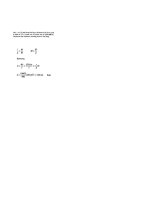
Stress determination
For skew loading and other forms of bending about principal axes
M,v
M,u
c=-+-
1, 1,
where
Mu
and
M,
are the components of the applied moment about the
U
and
V
axes.
Alternatively, with
0
=
Px
+
Qy
M,
=
PI,,
+
QIM
Myy
=
-Plyy
-
QIxy
Then the inclination of the N.A. to the
X
axis is given by
P
tana!
=
Q
As a further alternative,
M’n
1N.A.
o=-
where
M’
is the component of the applied moment about the N.A.,
IN.A.
is determined either
from the momenta1 ellipse or from the Mohr or Land constructions, and
n
is the perpendicular
distance from the point in question to the N.A.
Deflections of unsymmetrical members are found by applying standard deflection formulae
to bending about either the principal axes or the N.A. taking care to use the correct component
of load and the correct second moment of area value.
Introduction
It has been shown in Chapter
4
of
Mechanics
of
Materials
1
that the simple bending
theory applies when bending takes place about an axis which is perpendicular to a plane of
symmetry. If such an axis is drawn through the centroid of a section, and another mutually
perpendicular to it also through
the
centroid, then these axes are principal axes.
Thus
a plane
of symmetry is automatically a principal axis. Second moments of area of a cross-section
about its principal axes are found to
be
maximum and minimum values, while the product
second moment of area,
JxydA,
is found to be zero. All plane sections, whether they have
an axis of symmetry
or
not, have two perpendicular axes about which the product second
moment of area is zero.
Principal axes are thus de$ned as the axes about which the product
second moment
of
area is Zero.
Simple bending can then
be
taken as bending which takes
place about a principal axis, moments being applied
in
a plane parallel to one such axis.
In general, however, moments are applied about a convenient axis
in
the cross-section;
the plane containing the applied moment may not then
be
parallel to a principal axis. Such
cases are termed “unsymmetrical” or “asymmetrical” bending.
The most simple type of unsymmetrical bending problem
is
that of “skew” loading of
sections containing at least one axis of symmetry, as
in
Fig. 1.1. This axis and the axis
EJ.
Hearn,
Mechanics
of
Murerids
I,
Buttenvorth-Heinemann,
1997
$1.1
Unsymmetrical Bending
3
V
V
V
(c)
Rectangular
(b)
I-sectam
(c)
Channel
(d)
T-sectton
section section
Fig.
1
.I.
Skew loading
of
sections containing one
axis
of
symmetry.
perpendicular to it are then principal axes and the term skew loading implies load applied
at some angle to these principal axes. The method of solution in this case is to resolve
the applied moment
MA
about some axis
A
into its components about the principal axes.
Bending is then assumed to take place simultaneously about the two principal axes, the total
stress being given by
M,v
M,u
a=-+-
1,
I,
With at least one
of
the principal axes being an axis of symmetry the second moments of
area about the principal axes
I,
and
I,
can easily be determined.
With unsymmetrical sections (e.g. angle-sections, Z-sections, etc.) the principal axes are
not easily recognized and the second moments
of
area about the principal axes are not easily
found except by the use of special techniques to be introduced in
$3
1.3
and
1.4.
In such
cases an easier solution
is
obtained as will be shown in
51.8.
Before proceeding with the
various methods of solution of unsymmetrical bending problems, however, it is advisable
to
consider in some detail the concept of principal and product second moments of area.
1.1.
Product second moment
of
area
Consider a small element of area in a plane surface with a centroid having coordinates
(x,
y)
relative to the
X
and
Y
axes (Fig.
1.2).
The second moments
of
area of the surface
about the
X
and
Y
axes are defined as
zXx
=
Jy’d~
and
zYy
=
/x’&
(1.1)
Similarly, the product second moment of area of the section is defined as follows:
zXy
=
Jxy
(1.2)
Since the cross-section
of
most structural members used
in
bending applications consists
of a combination of rectangles the value of the product second moment
of
area for such
sections is determined by the addition of the
I,,
value for each rectangle (Fig.
1.3),
i.e.
Zxy
=
Ahk
(1.3)
4
Mechanics
of
Materials
2
51.2
Y
t
Fig.
1.2.
where
h
and
k
are the distances of the centroid of each rectangle from the
X
and
Y
axes
respectively (taking account of the normal sign convention for
x
and
y)
and
A
is the area
of
the rectangle.
k-
kt
h-
I
h-
Fig.
1.3.
1.2.
Principal second moments
of
area
The principal axes of a section have been defined in the introduction to this chapter.
Second moments of area about these axes are then termed principal values and these may
be related to the standard values about the conventional
X
and
Y
axes as follows.
Consider Fig. 1.4 in which
GX
and
GY
are
any two mutually perpendicular axes inclined
at
8
to the principal axes
GV
and
GU.
A small element
of
area
A
will then have coordinates
(u,
v)
to the principal axes and
(x,
y)
referred
to
the axes
GX
and
GY.
The area will
thus
have a product second moment of area about the principal axes given by
uvdA.
:. total product second moment of area of a cross-section
I,,
=
/"uvdA
=
S(xcosO+ysin8)(ycos8-xsine)~A
91.2
Unsymmetrical Bending
5
=
/(x
y
cos2
8
+
y2
sin 8 cos
8
-
x2 cos
8
sin
8
-
xy
sin2
8)
dA
=
(cos2
8
-
sin2
8)
/xy
dA
+
sin
8
cos
8
[/”
y2
dA
-
/x2
dA]
Y
Principal
axis
Fig.
1.4.
Now
for principal axes the product second moment of area is zero.
o
=
I,,
COS
28
+
4
(I,
-
zYy)
sin 28
This equation, therefore, gives the direction
of
the principal axes.
To
determine the second moments of area about these axes,
I,
=
v2
dA
=
(y cos
8
-
x
sin
dA
ss
=
cos2 8 y2
dA
+
sin2
8
/x2
dA
-
2cos8 sin
8 xydA
I
=
I,
cos2 8
+
I,,
sin2
8
-
I,,~
sin 28
Substituting for
I,,
from eqn.
(1.4),
sin228
I,=
;(1+cos28)Ixx+;(1-cos28)z,,
2
cos28
(I,r
-
1,)
(1.4)
=
;(I
+
cos 2011,
+
;
(1
-
cos 28)1,,
-
sec 213(1,,
-
I,)
+
;
cos
20(1,,.
-
I,)
I
-
-
(I,
+
I,,)
+
(I,
-
I,,)
cos 28
-
(I,,
-
I,)
sec 28
+
(Ivv
-
I,)
cos 213
6
Mechanics
of
Materials
2
i.e.
1
1,
=
TUxx
+zYy>
+
Similarly,
-
1,,)sec20
$1.3
(1.6)
I,
=
u2dA
=
(xcos8+ysin8)2dA
JJ
1
=
z(zxx
+
zyy)
-
;(L
-
zyy)
sec 28
N.B
Adding the above expressions,
I, +I,
=
I,,
+
I,,
Also from eqn.
(1
S),
I,
=
I,
cos2
8
+
I,,
sin2
8
-
I,,
sin
20
=
(1
+
cos
B)I,
+
(1
-
cos
20)1,,
-
I,,
sin
28
Z,
=
;(z~
+I,,)+
;(zxx
-Z,.~)COS~O-Z~S~~~~
(1.8)
Similarly,
I,,
=
;(zXx
+
zYy)
-
;(zX,
-
zYy) cos 28
+
z,,
sin 28
(1.9)
These equations are then identical in form with the complex-stress eqns. (1 3
.S)
and
(1
3.9)t
with
I,,
I,,,
and
I,,
replacing
a,,
oy
and
txy
and Mohr’s circle can be drawn to represent
I
values in exactly the same way as Mohr’s stress circle represents stress values.
13.
Mohr’s
circle
of
second moments
of
area
The construction is as follows (Fig.
1.5):
(1)
Set up axes for second moments of area (horizontal) and product second moments of
(2)
Plot the points
A
and B represented by
(I,,
I,,)
and
(I,,,
-Ixy).
(3)
Join AB and construct a circle with this as diameter.
This is then the Mohr’s circle.
(4)
Since the principal moments of area are those about the axes with a zero product second
area (vertical).
moment of area they are given by the points where the circle cuts the horizontal axis.
Thus
OC
and OD are the principal second moments of area
I,
and
I,.
The point
A
represents values on the
X
axis and
B
those for the
Y
axis. Thus, in order to
determine the second moment of area about some other axis, e.g. the N.A., at some angle
a!
counterclockwise to the
X
axis, construct a line from
G
at an angle
2a!
counterclockwise
to GA on the Mohr construction to cut the circle in point
N.
The horizontal coordinate of
N
then gives the value
of
IN.A.
t
E.J.
Hem,
Mechanics ofMuteriuls
I,
Butterworth-Heinemann,
1997.
$1.4
Unsymmetrical Bending
YV
7
Fig.
1.5.
Mohr's
circle
of
second moments
of
area.
The procedure is therefore identical to that for determining the direct stress
on
some plane
inclined at
CY
to
the plane on which
uX
acts in Mohr's stress circle construction, i.e.
angles
are DOUBLED
on Mohr's circle.
1.4.
Land's circle
of
second moments
of
area
An alternative graphical solution to the Mohr procedure has been developed by Land as
follows (Fig.
1.6):
Y
t
V
Fig.
1.6.
Land's circle
of
second moments
of
area.
(1)
From
0
as origin
of
the given
XY
axes mark
off
lengths OA
=
I,
and
AB
=
I,,
on the
vertical axis.