- Trang chủ >>
- Khoa Học Tự Nhiên >>
- Vật lý
processing and properties of nanocomposites, 2007, p.463
Bạn đang xem bản rút gọn của tài liệu. Xem và tải ngay bản đầy đủ của tài liệu tại đây (29.18 MB, 463 trang )
Suresh G. Advani
Processing and Properties of
NANOCOMPOSITES
Processing and Properties of
NAN0C0MP0S1TES Processing and Properties of
AN0C0MP0S
uresh G. Advani
University of Delaware, USA
\fc world Scientific
JEW JERSEY • LONDON • SINGAPORE • BEIJING • SHANGHAI • HONG KONG • TAIPEI • CHENNAI
Published by
World Scientific Publishing Co. Pte. Ltd.
5 Toh Tuck Link, Singapore 596224
USA office: 27 Warren Street, Suite 401-402, Hackensack, NJ 07601
UK office: 57 Shelton Street, Covent Garden, London WC2H 9HE
British Library Cataloguing-in-Publication Data
A catalogue record for this book is available from the British Library.
PROCESSING AND PROPERTIES OF NANOCOMPOSITES
Copyright © 2007 by World Scientific Publishing Co. Pte. Ltd.
All rights
reserved.
This
book,
or parts
thereof,
may not be reproduced in any form or by any means,
electronic or mechanical, including photocopying, recording or any information storage and
retrieval
system now known or to be
invented,
without written permission from the Publisher.
For photocopying of material in this volume, please pay a copying fee through the Copyright
Clearance Center, Inc., 222 Rosewood Drive, Danvers, MA 01923, USA. In this case permission to
photocopy is not required from the publisher.
ISBN 981-270-390-X
Printed by Fulsland Offset Printing (S) Pte Ltd, Singapore
Ifus booi^is dedicated
to the
memory
of my parents,
%amia andQopaCdas Advani
The field on nanotechnology is still in its infancy but continues to
progress at a much faster rate that any other field. Many methods to
synthesize nano particles, disperse them in a carrying fluid to form a
composite and exploit its extraordinary properties is the goal and dream
of many researchers engaged in this field. It is not possible to cover
every nano particulate matter and its role in materials revolution. The
approach adopted here was to focus on carbon nanotubes and nano clays
and explore their importance and their role in composites. Hence the
chapters presented in this book address processing, rheology, mechanical
properties and their interaction with fiber composites. Thus, this book is
a collection of nine chapters written by researchers who are at the
forefront of their field which address the role of nano particles in
composites. The first three chapters focus on the use of Carbon
nanotubes in a composite. Chapter
1
is a succinct summary of
the
state of
the art of
the
carbon nanotubes in composites. Chapter 2 focuses more on
the aspects of processing with these nano particles in a suspension. Most
research is focused in using these nanotubes sparingly in the composite
and exhibit disproportionally better properties. Chapter 3 focuses on how
to address higher loadings of these nanotubes and develop nanostructure
materials. Chapter 4 explores the interaction between traditional fiber
composites and use of nano particles in them in terms of benefits and
property enhancement in addition to processing of such materials.
Chapter 5 discusses in detail the rheology of suspensions that contain
nanofibers and how one can modify existing models to describe their
flow behavior. Chapters 6 through 9 address nano clay composites.
Chapter 6 is a good overview of
the
state of
the
art of the nanoclay usage
in various resins and composites. Chapter 7 focuses on the mechanical
and physical property characterization of polymer clay nanocomposites.
Vll
Vlll
Preface
Chapter 8 discusses further use of nanoclays in thermoplastics and their
use in glass fiber composites. Chapter 9 describes methods to prepare
nanoclay suspensions with thermosets and the corresponding
enhancement in properties. I would like to thank all the authors and
reviewers in making this project into reality.
Suresh Advani
GWLaird Professor of Mechanical Engineering
Associate Director, Center for Composite Materials
University of Delaware
Contents
Preface v
Chapter 1
Carbon Nanotube/Nanofibre Polymer Composites 1
Milo Shaffer and Jan Sandler
Chapter 2
Dispersion, Bonding and Orientation of Carbon Nanotubes
in Polymer Matrices 61
Suresh Advani and Zhihang Fan
Chapter 3
SWNT Buckypaper Nanocomposites: High Nanotube Loading
and Tailoring Nanostructures 99
Zhiyong (Richard) Liang, Ben Wang and Chuck Zhang
Chapter 4
Processing and Mechanical Properties Characterization of
Hybrid Thermoset Polymer Composites with Micro-Fiber
and Carbon Nano-Fiber Reinforcements 141
Kuang-Ting Hsiao
Chapter 5
Shear Rheology of Nanofiber Suspensions and
Nanofiber/Polymer Melt Composites 191
Jianhua Xu, Yingru Wang, Christopher Kagarise,
Kurt W. Koelling and Stephen E. Bechtel
IX
X
Content
Chapter 6
Recent Advances in Polymer/Layered Silicate Nanocomposites:
An Overview from Science to Technology 247
Masami Okamoto
Chapter 7
Polymer-Clay Nanocomposites — A Review of Mechanical
and Physical Properties 307
Zhong-Zhen Yu, Aravind Dasari, Yiu-Wing Mai
Chapter 8
Preparative Methods and Properties of Polypropylene/Layered
Silicate Nanocomposites 359
Joong-Hee Lee, Prashantha Kalappa, Chang-Eui Hong,
Nam Hoon Kim and Gye-Hyoung
Chapter 9
Clay Nanocomposites Of Polyurethanes And Epoxies:
Preparation Methods And Properties 419
Sadhan
C.Jana
CHAPTER 1
Carbon Nanotube/Nanofibre Polymer Composites
Milo S.P. Shaffer
1
and Jan K.W. Sandler
2
Department of Chemistry, Room 103d RCS1
Imperial College London, SW7
2AZ,
UK
Tel: +44(0)20 7594 5825; Fax: +44(0)20 7594 5801
m.
shaffer@imperial.
ac.
uk
Polymer Engineering, University of Bayreuth
Universitdtsstrasse
30,
D-95447 Bayreuth, Germany
jan.
sandler@uni-bayreuth. de
1.
Introduction
Although the terms nanomaterial and nanocomposite represent new and
exciting fields in materials science, such materials have actually been
used for centuries and have always existed in nature. However, it is only
recently that the means to characterise and control structure at the
nanoscale have stimulated rational investigation and exploitation. A
nanocomposite is defined as a composite material where at least one of
the dimensions of one of its constituents is on the nanometre size scale
[1].
The term usually also implies the combination of two (or more)
distinct materials, such as a ceramic and a polymer, rather than
spontaneously phase-segregated structures. The challenge and interest in
developing nanocomposites is to find ways to create macroscopic
components that benefit from the unique physical and mechanical
properties of very small objects within them.
Natural materials such as bone, tooth, and nacre are very good
examples of the successful implementation of this concept, offering
excellent mechanical properties compared to those of their constituent
materials. Such composites actually exhibit beautifully organised levels
of hierarchical structure from macroscopic to microscopic length scales,
1
2
M. S. P. Shaffer and J. K.
W.
Sandler
and provide a powerful motivation for improving our processing control.
Currently, we are striving to understand the behaviour of just the smallest
building blocks in such materials which are the natural versions
of nanocomposites. Significantly, two contrasting phases are often
combined: a hard nanoscale reinforcement (such as hydroxyapatite or
calcium carbonate) is embedded in a soft, usually protein-based, matrix.
Although the composite character of these materials itself plays a crucial
role,
the question remains, why the nanometre scale is so important.
From a simple mechanical point of view, the situation in such
biocomposites is quite familiar: the matrix transfers the load via shear to
the nanoscale reinforcement [2]. A large length-to-diameter (aspect) ratio
of the mineral reinforcement compensates for the low modulus of the
soft protein matrix, leading to an optimised stiffness of the composite.
The fracture toughness of such biocomposites, on the other hand, hinges
on the ultimate tensile strength, <r
f
, of the reinforcement. Crucially, the
use of a nanomaterial allows access to the maximum theoretical strength
of the material, since mechanical properties become increasingly
insensitive to flaws at the nanoscale [2]. This observation is an extension
of the classic approach to strong materials, namely to reduce the
dimensions until critical flaws are excluded. At the nanoscale, highly
crystalline reinforcements are used in which all but the smallest atomistic
defects can be eliminated. It is clear that a high aspect ratio must be
maintained in order to ensure suitable stress transfer. This general
concept of exploiting the inherent properties of nanoscaled materials is
not limited to the mechanical properties of a material, since a wide range
of physical properties also depend on defect concentrations. In addition,
the small size scale can generate inherently novel effects through, for
example, quantum confinement, or through the dramatic increase in
interfacial area.
The concept of creating both structural and functional multi-phase
nanocomposites with improved performance is currently under
development in a wide variety of metallic, ceramic, and polymeric
matrices, although the emphasis to date has been on polymeric systems.
Similarly, the filler particles can be organic or inorganic with a wide
range of material compositions and structures. The resulting composites
generally exhibit a number of enhanced properties, so that the material
Carbon Nanotube/Nanofibre Polymer Composites
3
cannot easily be classified as a structural or functional composite. The
term reinforcement, as opposed to plain filler, is equally frequently used
for the nanoscale component, without a clear distinction.
Carbon nanotubes (CNTs) have attracted particular interest because
they are predicted, and indeed observed, to have remarkable mechanical
and other physical properties. The combination of these properties with
very low densities suggests that CNTs are ideal candidates for high-
performance polymer composites; in a sense they may be the next
generation of carbon fibres. Although tens or hundreds of kilograms of
carbon nanotubes are currently produced per day, the development of
high-strength and high-stiffness polymer composites based on these
carbon nanostructures has been hampered so far by the lack of
availability of high quality (high crystallinity) nanotubes in large
quantities. In addition, a number of fundamental challenges arise from
the small size of these fillers. Although significant advances have been
made in recent years to overcome difficulties with the manufacture of
polymer nanocomposites, processing remains a key challenge in fully
utilising the properties of the nanoscale reinforcement. A primary
difficulty is achieving a good dispersion of the nanoscale filler in a
composite, independent of filler shape and aspect ratio. Without proper
dispersion, filler aggregates tend to act as defect sites which limit the
mechanical performance; such agglomerates also adversely influence
physical composite properties such as optical transmissivity.
When dispersing small particles in a low viscosity medium, diffusion
processes and particle-particle and particle-matrix interactions play an
increasingly important role as the diameter drops below 1 um. It is not
only the absolute size but rather the specific surface area of the filler, and
the resulting interfacial volumes, which significantly influence the
dispersion process. These regions can have distinctly different properties
from the bulk polymer and can represent a substantial volume fraction of
the matrix for nanoparticles with surface areas of the order of hundreds
of m /g. The actual interphase volume depends on the dispersion and
distribution of the filler particles, as well as their surface area.
In traditional fibre composites, the interfacial region is defined as the
volume in which the properties deviate from those of the bulk matrix or
4
M. S. P. Shaffer and J. K.
W.
Sandler
filler [3]. However, it is simpler, in the case of small particles, to
consider a straightforward calculation [4] of
the
interparticle distance s:
'( n V
/3
s
=
d* —- -1 , (1)
\60v
J
where d is the diameter and
<f>
Y
is the volume fraction of uniformly-sized,
spherical particles on a lattice. As an example, a 15 vol% loading of
10 nm diameter particles leads to an interparticle distance of only 5 nm.
This figure, which is similar to the radius of gyration of a typical
polymer molecule, shows that essentially the entire polymer matrix in a
nanocomposite can behave as if it were part of an 'interphase'. In other
words, the properties of the whole matrix may differ from the pure bulk
polymer in terms of the degree of cure, chain mobility, chain
conformation, and degree of chain ordering or crystallinity. These effects
may influence both processing and final properties of the polymeric
phase. One simple but important consequence is that it becomes
increasingly difficult to 'wet' adequately all of the nanofiller surface with
polymer; thus, the volume fraction of nanomaterial that can be uniformly
dispersed using conventional processing techniques is decreased. In
addition, the strong influence of interfacial interactions during processing
can alter the matrix microstructure which, particularly in the case of
semicrystalline polymers, can significantly affect the mechanical
behaviour of the nanocomposite independently of direct load-bearing by
the filler [5]. Therefore, the matrix microstructure must be critically
assessed when evaluating the performance of carbon nanotube-polymer
composites. Although the high aspect ratio of carbon nanotubes generally
appears to be a clear benefit for the exploitation of their mechanical as
well as physical properties such as electrical conductivity, it is as yet not
established which of
the
many different types of nanotubes will yield the
ultimate performance in a polymer composite. Nanotubes have shown a
remarkable range of structural features, and the resulting structure-
property-relationships are only slowly emerging.
Carbon Nanotube/Nanofibre Polymer Composites
5
2.
Carbon Nanotubes and Nanofibres
Carbon nanotubes are often seen as the intersection of traditional carbon
fibres with the fullerene family [6]. It was only realised relatively
recently that solids of pure elemental carbon with sp
2
-hybridisation can
form a wide variety of well-defined crystalline structures. The first
recognition of the fullerenes as closed structures [7] in 1985, and their
subsequent synthesis in a carbon arc [8], stimulated enormous new
interest in carbon materials. In 1991, Iijima observed a graphitic tubular
structure in an arc discharge apparatus that was used to produce C
60
and
other fullerenes. His realisation [9] of the structural richness of these
particles, which came to be known as nanotubes, generated enormous
interest; indeed, there are now in excess of 10,000 papers discussing the
science of CNTs, including a large fraction on polymer composites.
Although Iijima is often credited with the discovery of CNTs, there are
earlier reports in the literature, notably by Endo in 1976, of the synthesis
of tubular carbon structures using hydrocarbon decomposition [10].
There are even reports in the catalysis literature of the 1950s of attempts
to remove troublesome fibrous carbon deposits. The electric arc method
was actually used as early as 1960 by Roger Bacon [11] to produce
graphite whiskers, and one can also speculate that nanotubes were likely
present in his experiments as a by-product, although unobserved. The
explosion of interest in 1991 was driven by the renewed interest in
carbon following the discovery of fullerenes, and the structural
perfection of lijima's nanotubes which implied a whole range of exciting
properties.
CNTs have typical diameters in the range of ~1—50 nm and lengths of
many microns (even centimetres in special cases). They can consist of
one or more concentric graphitic cylinders. In contrast, commercial
(PAN and pitch) carbon fibres are typically in the 7-20 urn diameter
range, while vapour-grown carbon fibres (VGCFs) have intermediate
diameters ranging from a few hundred nanometres up to around a
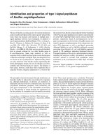
millimetre. The variation in diameter of fibrous graphitic materials is
summarised in Figure 1. Crucially, conventional carbon fibres do not
have the same potential for structural perfection that can be observed in
CNTs. Indeed, there is a general question as to whether the smallest
6 M. S. P. Shaffer and
J.
K. W. Sandler
CNTs should
be
regarded
as
very small fibres
or
heavy molecules, since
the diameters
of
the smallest nanotubes
are
similar
to
those
of
common
polymer molecules. This ambiguity
is
characteristic
of
nanomaterials,
and
it is not yet
clear
to
what extent conventional fibre composite
understanding can be extended to CNT composites.
Diameter
10 Mm
1
pm
0.1
urn
10
nm
1
nm
Carbon fibres
Graphite whiskers
Vapour-grown carbon fibres
V
Carbon nanofibres
-II'
Carbon nanotubes
1
Fullerenes (Ceo, C
70
,
etc.)
Fig. 1. Comparison of diameters of various fibrous carbon-based materials.
The nanotube structure can be defined more exactly by considering
a
single-wall carbon nanotube (SWCNT)
as a
conformal mapping
of the
two-dimensional hexagonal lattice
of a
single graphene sheet onto
the
surface
of a
cylinder.
The
graphite sheet
may be
'rolled'
in
different
orientations along
any
two-dimensional lattice vector (m,n) which then
maps onto
the
circumference
of
the resulting cylinder;
the
orientation
of
the graphite lattice relative
to the
axis defines
the
chirality
or
helicity
of
the nanotube [12]. As-grown, each nanotube
is
closed
at
both ends
by a
hemispherical
cap
formed
by the
replacement
of
hexagons with
pentagons
in the
graphite sheet which induces curvature. SWCNTs
are
usually obtained
in the
form
of
so-called ropes
or
bundles, containing
between 20 and 100 individual tubes packed
in a
hexagonal array [13-16].
Rope formation
is
energetically favourable
due to the Van der
Waals
attractions between isolated nanotubes [17]. Multi-wall carbon nanotubes
(MWCNTs) provide
an
alternative route
to
stabilisation. They consist
of
Carbon Nanotube/Nanofibre Polymer Composites
1
two or more coaxial cylinders, each rolled out of single sheets, separated
by approximately the interlay er spacing in graphite. The outer diameter
of such MWCNTs can vary between 2 and a somewhat arbitrary upper
limit of about 50 nm; the inner hollow core is often (though not
necessarily) quite large with a diameter commonly about half of that of
the whole tube. Carbon nanofibres (CNFs) are mainly differentiated from
nanotubes by the orientation of the graphene planes: whereas the
graphitic layers are parallel to the axis in nanotubes, nanofibres can show
a wide range of orientations of the graphitic layers with respect to the
fibre
axis.
They can be visualised as stacked graphitic discs or
(truncated) cones, and are intrinsically less perfect as they have graphitic
edge terminations on their surface. Nevertheless, these nanostructures
can be in the form of hollow tubes with an outer diameter as small as
~5 nm, although 50-100 nm is more typical. The stacked cone geometry
is often called a 'herringbone fibre' due to the appearance of the
longitudinal cross-section. Slightly larger (100-200 nm) fibres are also
often called CNFs, even if the graphitic orientation is approximately
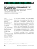
parallel to the axis. Representative transmission electron micrographs of
commercially available nanofibres with a mean outer diameter of around
150 nm are shown in Figure 2. The schematic diagram highlights the
orientation of the graphitic planes in the inner and outer regions of the
nanofibre wall, and is intended to illustrate the structural complexity that
can arise in these materials.
A variety of synthesis methods now exist to produce carbon
nanotubes and nanofibres. However, these carbon nanostructures differ
greatly with regard to their diameter, aspect ratio, crystallinity,
crystalline orientation, purity, entanglement, surface chemistry, and
straightness. These structural variations dramatically affect intrinsic
properties, processing, and behaviour in composite systems. However, it
is not yet clear which type of nanotube material is most suitable for
composite applications, nor is there much theoretical basis for rational
design. Ultimately, the selection will depend on the matrix material,
processing technology, and the property enhancement required. Thus, in
order to interpret the data obtained for nanotube composites, and to
develop the required understanding, it is essential to appreciate the range
of nanotube materials available.
8 M. S. P. Shaffer and J. K.
W.
Sandler
Fig. 2. Representative transmission electron micrographs of commercial carbon
nanofibres, highlighting structural variations both in overall morphology and in the
orientation of the graphitic planes. The leftmost image shov/s a 'bamboo' and a
'cylindrical' CNF, whilst the rightmost image shows a high magnification image of one
wall of the cylindrical fibre which reveals the graphitic arrangement sketched in the
central panel.
2.1.
Production methods
Both MWCNTs and SWCNTs can be produced by a variety of different
processes which can broadly be divided into two categories: high-
temperature evaporation using arc-discharge [13,14,18-20] or laser
ablation [15,21], and various chemical vapour deposition (CVD) or
catalytic growth processes [16,22-24]. In the high-temperature methods
MWCNTs can be produced from the evaporation of pure carbon, but the
synthesis of SWCNTs requires the presence of a metallic catalyst. The
CVD approach requires a catalyst for both types of CNTs but also allows
the production of
CNFs.
Many variants exist, but the basic methods can
be described as follows.
The electric arc method is based on the generation of
a
DC arc plasma
between two carbon electrodes in an inert (usually helium) atmosphere.
While the anode is consumed, a soft, dark black, fibrous deposit forms
on the cathode which consists of about 50 vol% straight MWCNTs, often
arranged in a fractal structure. Addition of a suitable catalyst such as Ni-
Co,
Co-Y or Ni-Y leads to the formation of interconnected web-like
SWCNT bundles on the walls of the reaction chamber [13,14,25,26].
Macroscopically long ropes of well-aligned SWCNTs can be synthesised
Carbon Nanotube/Nanofibre Polymer Composites
9
by the arc-discharge method using hydrogen [27]. Laser ablation is a
similar process, using a different technique to generate the carbon
vapour; although the method can generate MWCNTs, it is usually used
for the production of SWCNTs at yields higher than 70%. A graphite
target, containing a 1-2% metal catalyst, is held in a furnace at 1200°C
in an inert atmosphere and is evaporated using a high power laser
[15,28].
The resulting products are swept from the high-temperature zone
by the flowing inert gas and are deposited on a conical water-cooled
copper collector.
The products of both high-temperature routes tend to be highly
crystalline, with low defect concentrations, but are relatively impure,
containing other, unwanted carbonaceous impurities. These methods
usually work on the gram scale and are, therefore, relatively expensive.
For the use of nanotubes in composites, large quantities of nanotubes are
required at low cost, ideally without the requirement for complicated
purification. At present, only CVD-grown nanotubes satisfy these
requirements and, as such, tend to be the materials of choice for
composite work, both in academia and in industry. The main
contaminants in CVD materials are residual catalyst particles which are
mostly incorporated into the nanotubes. On the other hand, these gas-
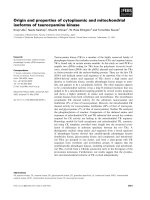
phase processes operate at lower temperatures and lead to structurally
more imperfect nanotubes, as shown by the deviation from the ideal
cylindrical structure in Figure 3.
Carbon filaments can form when small metal particles, almost always
containing iron, nickel, or cobalt, are exposed to CO or hydrocarbon
gases at temperatures between 500 and 1200°C. The carbonaceous
feedstock decomposes on the catalyst, generating carbon which diffuses
through or around the catalyst to produce a fibre with a diameter similar
to the metal particle [29]. Originally, the method was developed for
growing VGCFs with diameters up to several hundred micrometres
through simultaneous pyrolytic overgrowth on the primary fibre. Later,
various orientations of the graphitic planes with respect to the fibre axis
were observed depending on the crystallographic orientation of the
catalyst particle [30]. The arrangement of the graphitic planes can vary
from perpendicular to the fibre axis to parallel, thus generating a range of
!()
A/.
& R ^^#T ;^J
J.
^.
j^.
^nJ&f
Fig.
3. Transmission electron micrographs of commercial MWCNTs grown by CVD
methods,
with
the
beam perpendicular
(left)
and
parallel (right) to
the axis.
CNF structures
[31].
Twisted,
helical,
and branched nanofibres have also
been reported
[32].
Under the right conditions, entangled mats of catalytically-grown
CNTs can be produced
[22].
Generally,
the experiment
is
carried out in a
flow furnace at atmospheric pressure
[33,34].
In perhaps the simplest
embodiment, the catalyst is placed in a ceramic boat which is then put
into a quartz tube. A reaction mixture consisting of, for example,
acetylene and argon is passed over the catalyst bed for several hours at
temperatures ranging from 500 to 1100°C
[34].
In
fact,
there are many
options fbr introducing the catalyst ranging from injection of
organometallic vapours and metallic
colloids,
to pre-deposition of metal
films or particles on ceramic
supports.
Injecting the catalyst into the gas
stream allows fbr the continuous production of
nanotubes.
A number of
commercial routes to the production of vapour-grown CNFs and CNTs
are based on a 'floating catalyst' carried in the gas stream inside a
continuous flow reactor
[35].
The CVD products discussed above tend to be highly entangled;
however,
aligned nanotube an*ays, as shown in Figure 4a, can be
obtained under conditions that lead to rapid and dense nucleation on flat
substrates
[36-39].
With sufficient growth
time,
lengths in the millimetre
Carbon Nanotube/Nanofihre Polymer Composites
11
range have been observed [40]. Such aligned MWCNT films can be
easily removed from the substrate and might be considered as the ideal
nanotube material for composite applications, as the low degree of
nanotube entanglement should allow straightforward dispersion in a
polymer matrix. The synthesis of well-aligned and comparatively straight
MWCNTs on substrates can be further enhanced by the application of a
plasma during growth [41,42]. This approach has recently been shown to
allow the production of aligned nanotube films at temperatures as low as
120°C [43], opening the door for direct nanotube growth on polymer
substrates. The use of plasma accelerates growth, and increases
alignment, but tends to reduce crystallinity.
Although a number of commercial C VD routes to S WCNTs exist, the
so-called 'HiPco' process has received particular attention. The gas-
phase growth of SWCNTs using high-pressure carbon monoxide as the
carbon source was developed by Nikolaev et al. [44] but is now
commercially exploited by Carbon Nanotechnologies Inc., USA. The
product is shown in Figure 4b and is widely used for research purposes,
although it is, at present, still too expensive for large-scale commercial
composite applications.
Fig. 4. Scanning electron micrographs of (a) aligned multi-wall carbon nanotubes and
(b) HiPco single-wall carbon nanotubes produced by CVD methods.
In summary, the quality and yield of carbon nanotubes depend on the
synthesis technique and the specific growth conditions used. Catalytic
processes generally involve lower growth temperatures which lead to
12
M. S. P. Shaffer and
J.
K.
W.
Sandler
both variations in the orientation of the graphitic planes with respect to
the tube axis and to an increased concentration of structural defects. It is
not surprising that most studies aimed at investigating the fundamental
mechanical and physical properties of individual nanotubes have been
performed on high-temperature materials with few structural defects.
Relatively little effort has been applied to CNFs, although given their
structural appearance, their properties should, at best, resemble those of
very defective catalytic nanotubes.
2.2.
Mechanical properties of carbon nanotubes
Although challenging, a number of experimental studies have focussed
on the direct determination of the mechanical properties of individual
carbon nanotubes. Experimental measurements of nanotube deformations
have mostly been analysed by assuming nanotubes to be elastic beams.
The resulting elastic constants belong to the framework of continuum
elasticity, and any estimate of these material parameters for nanotubes
therefore implies the continuum assumption. There is also a general
question as to what should be taken as the cross-section of a nanotube.
For MWCNTs, values have usually been calculated based on a thick-
walled cylinder, ignoring the cross-section of the hollow core, although it
might be argued that the area of
the
core should be included since it is an
intrinsic feature of
the
structure. The question is even more difficult with
SWCNTs which are only a single layer of atoms thick. Usually, the
thickness, t, is taken to be the interlayer spacing of graphite, although
difficulties with bending stiffness remain [45].
The original determinations of CNT stiffness were based on
observing the amplitude of thermal vibrations in a TEM; average
stiffness values of 1.8 TPa [46] and 1.25 TPa [47] were obtained for
MWCNTs and SWCNTs, respectively. For MWCNTs, the estimated
nanotube stiffness appeared to depend on the diameter [48], an effect that
was explained by the occurrence of wave-like distortions for multi-wall
carbon nanotubes with diameters of greater than 12 nm, as predicted by a
combination of finite element analysis and non-linear vibration analysis
Carbon Nanotube/Nanofibre Polymer Composites
13
[49].
Falvo et
al.
[50] showed that MWCNTs could be repeatedly bent to
large angles (> 120°) with an AFM tip without undergoing catastrophic
failure; this observation was supported by high-resolution TEM studies
that indicated reversible buckling as a mechanism for stress relief
[51-53].
Lourie et
al.
captured the buckling of SWCNTs in compression
and bending by embedding the nanotubes in a polymer film [54].
Static models of beam bending have also been used to quantify
mechanical properties of nanotubes. AFM measurements led to an
average bending stiffness of arc-grown MWCNTs of about 1 TPa
[55,56];
however, catalytic nanofibres with a higher defect concentration
were found to have a substantially lower stiffness of only 10 to 50 GPa
[56].
Whereas point defects do not affect the nanotube stiffness greatly,
deviations from a perfectly parallel alignment of the graphitic layers to
the axis have a significant detrimental effect on properties, due to the
high anisotropy of graphite.
More recently, a mechanical loading stage operating inside an SEM
was used to perform the first in-situ tensile tests on individual MWCNTs
and ropes of SWCNTs. Individual arc-grown MWCNTs were found to
fracture by a so-called sword-in-sheath mechanism in the outermost
shell. Strength values for the outer shell ranged from 11 to 63 GPa
at fracture strains of up to 12% and modulus values ranged from 270 to
950 GPa [57]. By assuming that the load is carried only by the SWCNTs
on the perimeter of the rope, fracture strengths ranging from 13 to
52 GPa and moduli between 320 and 1470 GPa were obtained [58]. It is
interesting to note that the maximum fracture strain was found to be
5.3%
which is close to the theoretical value of
~5%
for defect nucleation
in individual SWCNTs [59].
The experimental results for highly crystalline nanotubes (produced
by high-temperature methods) show that such nanotubes can indeed have
a Young's modulus approaching the theoretical value of 1.06 TPa [52],
the in-plane modulus of graphite, in agreement with theoretical studies
[60,61].
(Young's modulus values of around 5.5 TPa [46] relate to an
assumed effective SWCNT wall thickness of 0.066 nm). It should be
borne in mind that a single value of Young's modulus should not be
uniquely used to describe both the tension/compression and bending
14
M. S. P. Shaffer and
J.
K.
W.
Sandler
behaviour of carbon nanotubes. Tension and compression are mostly
governed by the in-plane er-bonds, while pure bending is affected by the
out-of-plane ;r-bonds. However, within a given mode, continuum
elasticity does seem to be applicable to the elastic properties of such
nanostructures, up to the point at which local instabilities occur, as long
as the geometry of the nanotubes is properly taken into account.
A number of theoretical studies have addressed the structural stability
of nanotubes in tension, compression, bending, and torsion. Under axial
loads,
abrupt changes in nanotube morphology were observed which
depended on the nanotube length [62,63]. Nanotube buckling due to
bending has also been demonstrated [62,64] and is characterised by a
collapse of the cross-section in the middle of the tube, in agreement with
experimental observations [51-53].
The strength of nanotubes depends on the distribution of defects, as
well as interlayer interactions in MWCNTs and bundles of SWCNTs.
The defect density is potentially low in these nanostructures and defect
sites may be distributed over large distances due to the small diameter
and high aspect ratio. However, defect density will depend on the growth
process, and the strength should only approach the theoretical limit for
nanotubes grown at high-temperatures. There are relatively few
experimental results but those mentioned above are in good agreement
with theoretical predictions [65] and indeed indicate that the strength of
nanotubes can be one order of magnitude higher than that of current
high-strength carbon fibres. Further evidence for the high strength of
high temperature nanotubes has been found in other tensile tests [66],
although the strength decreased significantly for 2 mm long bundles of
MWCNTs grown in a CVD process [67]. In this case, the average
strength of about 1.7 GPa might be related to the higher defect
concentration as a result of the lower growth temperature, but could also
be attributed to gauge length effects, with individual nanotubes being
shorter than the overall length of the bundle. Initial fragmentation tests of
nanotubes embedded in thin film polymer composite films also led to an
estimated high tensile strength of nanotubes [68,69], although an
accurate determination of the fragment length of an embedded nanotube
in a TEM sample is challenging.