- Trang chủ >>
- Khoa Học Tự Nhiên >>
- Vật lý
nanostructured materials for solar energy conversion, 2006, p.615
Bạn đang xem bản rút gọn của tài liệu. Xem và tải ngay bản đầy đủ của tài liệu tại đây (11.09 MB, 615 trang )
Nanostructured Materials for Solar
Energy Conversion
PRELIMS.qxd 11/11/2006 12:08 PM Page i
This page intentionally left blank
Nanostructured Materials for Solar
Energy Conversion
Edited By
Tetsuo Soga
Department of Environmental Technology and Urban Planning
Nagoya Institute of Technology
Nagoya, Japan
Amsterdam
●
Boston
●
Heidelberg
●
London
●
New York
●
Oxford
Paris
●
San Diego
●
San Francisco
●
Singapore
●
Sydney
●
Tokyo
PRELIMS.qxd 11/11/2006 12:08 PM Page iii
Elsevier
Radarweg 29, PO Box 211, 1000 AE Amsterdam, The Netherlands
The Boulevard, Langford Lane, Kidlington, Oxford OX5 1GB, UK
First edition 2006
Copyright © 2006 Elsevier B.V. All rights reserved
No part of this publication may be reproduced, stored in a retrieval system
or transmitted in any form or by any means electronic, mechanical, photocopying,
recording or otherwise without the prior written permission of the publisher
Permissions may be sought directly from Elsevier’s Science & Technology Rights
Department in Oxford, UK: phone (+44) (0) 1865 843830; fax (+44) (0) 1865 853333;
email: Alternatively you can submit your request online by
visiting the Elsevier web site at and selecting
Obtaining permission to use Elsevier material
Notice
No responsibility is assumed by the publisher for any injury and/or damage to persons
or property as a matter of products liability, negligence or otherwise, or from any use
or operation of any methods, products, instructions or ideas contained in the material
herein. Because of rapid advances in the medical sciences, in particular, independent
verification of diagnoses and drug dosages should be made
Library of Congress Cataloging-in-Publication Data
A catalog record for this book is available from the Library of Congress
British Library Cataloguing in Publication Data
A catalogue record for this book is available from the British Library
ISBN-13: 978-0-444-52844-5
ISBN-10: 0-444-52844-X
Printed and bound in The Netherlands
06 07 08 09 10 10987654321
For information on all Elsevier publications
visit our website at books.elsevier.com
PRELIMS.qxd 11/11/2006 12:08 PM Page iv
Preface
Our society is based on coal, oil and natural gas, but these fossil fuels will
be depleted someday in the future because they are limited. Carbon dioxide
is produced in the combustion of fossil fuels and the rapid increase of car-
bon dioxide concentration has affected the consequence of climate, result-
ing in the global warming effect. Under these circumstances, interest in
photovoltaic (PV) solar cell is increasing rapidly as an alternative and clean
energy source.
Photovoltaic solar cells provide clean electrical energy because the
solar energy is directly converted into electrical energy without emitting
carbon dioxide. The solar energy is not limited, free of charge and distrib-
uted uniformly to all human beings. Crystalline silicon solar cell has been
extensively studied and used for practical terrestrial applications. However,
the expensive material cost and lots of energy necessary for manufacturing
have caused high cost and long energy payback time, which have prevented
the large spread of PV power generation.
Recently, thin film solar cells using silicon or compound semiconduc-
tors have been actively studied instead of the bulk silicon solar cell. But the
solar cells are still too expensive to compete with public electricity charge.
In 2004 New Energy and Industrial Technology Development Organization
(NEDO), Ministry of Economy, Trade and Industry, Japan, announced the
“PV Roadmap Toward 2030 (PV2030)” in which the target of production
cost for PV module is 50 yen/W in 2030. It is expected that the PV power
generation can supply approximately 50% of residential electricity con-
sumption (approximately 10% of total electricity consumption) in 2030.
But it would be difficult to reach this goal only by the conventional tech-
nologies. One important concept to reduce the solar cell cost and to increase
the conversion efficiency is to use NANOTECHNOLOGY, i.e., to use the
v
PREFACE.qxd 11/11/2006 12:08 PM Page v
vi Preface
nanostructured material in solar cell. Nanostructured materials are largely
divided into inorganic materials and organic materials. In spite of the com-
mon interest and common purpose, two kinds of materials have been dis-
cussed in different conferences and different communities until now. There
is no book that offers a comprehensive overview of the nanostructured inor-
ganic and organic materials for solar energy conversion.
The aim of this book is to overview the nanostructured materials for
solar energy conversion covering a wide variety of materials and device types
from inorganic materials to organic materials. This book is divided into five
parts: fundamentals of nanostructured solar cells, nanostructures in conven-
tional thin film solar cells, dye-sensitized solar cells, organic and carbon
based solar cells and other nanostructures. Authors are all specialists in their
fields. But I must apologize that the important nanostructured materials are
missing in this book because of the limit of my ability. This book was
intended for researchers, scientists, engineers, graduate students and under-
graduate students, majoring in electrical engineering, chemical engineering,
material science, physics, etc., who are interested in the nanostructured solar
cells. The content of my chapter is the subject of a graduate course in our
department, Department of Environmental Technology and Urban Planning,
devoted for the beginner of PV. I strongly hope that you will get some hints
for the development of the solar cell from this book and contribute to the
progress of PV.
Tetsuo Soga
Nagoya, Spring 2006
PREFACE.qxd 11/11/2006 12:08 PM Page vi
Introduction
Tetsuo Soga
Department of Environmental Technology and Urban Planning
Nagoya Institute of Technology
Gokiso-cho, Showa-ku, Nagoya 466-8555, Japan
Energy conversion in solar cell consists of generation of electron–hole pairs
in semiconductors by the absorption of light and separation of electrons and
holes by an internal electric field. Charge carriers collected by two electrodes
give rise to a photocurrent when the two terminals are connected externally.
When a resistance load is connected to the two terminals, the separation of
the charge carriers sets up a potential difference.
Most of the solar cells used in the terrestrial applications are bulk-type
single- or multi-crystalline silicon solar cells. The typical cell structure is a
thin (less than 1 m) n-type emitter layer on a thick (about 300 m) p-type
substrate. Photo-generated electrons and holes diffuse to the space charge
region at the interface where they are separated by the internal electric field.
The effective charge separation results from long diffusion length of electrons
and holes in crystalline silicon. Although it is aimed to reduce the solar cell
module manufacturing cost, the drastic reduction of cell cost and increase
of the conversion efficiency cannot be expected by using the conventional
materials and solar cell structures. Moreover, the shortage of the feedstock
of high-purity silicon is predicted in the near future although it depends on
off-spec silicon of electronics industry. Therefore, research and develop-
ment of solar cells with low production cost, high conversion efficiency and
low feedstock consumption are required.
An important concept to reach this goal is to use nanostructured mate-
rials instead of bulk materials. The motivations to employ nanostructures in
solar cells are largely divided into three categories as follows:
1. To improve the performance of conventional solar cells.
2. To obtain relatively high conversion efficiency from low grade
(inexpensive) materials with low production cost and low-energy
consumption.
vii
INTRO.qxd 11/11/2006 12:09 PM Page vii
3. To obtain a conversion efficiency higher than the theoretical limit
of conventional p–n junction solar cell.
This book brings out an overview of the organic and inorganic nano-
structured materials for solar energy conversion. The book comprises of five
parts as follows:
PART I. FUNDAMENTALS OF NANOSTRUCTURED
SOLAR CELLS
The fundamental issues to deal with nanostructured solar cells are described
on device modeling, optical and electrical modeling and modeling of refrac-
tive index and reflectivity of quantum solar cells. The chapter on basic proper-
ties of semiconductor materials and the conventional p–n junction solar cells
deals with nanostructured solar cells.
PART II. NANOSTRUCTURES IN CONVENTIONAL THIN
FILM SOLAR CELLS
Nanostructures of conventional thin film solar cells such as silicon solar cells,
chalcopyrite-based solar cells, CdS-based solar cells and CdTe-based solar
cells are described. Amorphous silicon has attracted attention to reduce the
manufacturing cost compared with bulk-type crystalline silicon. But there
still remains a problem of stability. Recently, microcrystalline thin film silicon
solar cells made up of nano-sized crystallites with the material properties
between amorphous and bulk have been studied actively. It is expected to
obtain very high conversion efficiency (more than 15%) by employing amor-
phous silicon/microcrystalline silicon tandem solar cells. It also describes
that it is possible to improve the performance and reduce the cost of thin
film solar cells based on chalcopyrite-based materials, CdS, CdTe and Cu
2
S.
PART III. DYE-SENSITIZED SOLAR CELLS
The principle and the current status of dye-sensitized solar cells are described.
In the conventional p–n junction solar cells, only the electrons and holes
that can diffuse to the space charge region can be collected as a current. In
order to get a long diffusion length, the purity of semiconductors should be
increased and the defect concentration should be decreased, resulting in the
expensive solar cell materials. In a dye-sensitized solar cell, a photon absorbed
viii Tetsuo Soga
INTRO.qxd 11/11/2006 12:09 PM Page viii
by a dye molecule gives rise to electron injection into the conduction band
of nanocrystalline oxide semiconductors such as TiO
2
or ZnO. Because of the
high surface area, relatively high photocurrent can be obtained in spite of
the simple process. The dye is regenerated by electron transfer from a redox
species in solution. A chapter on solid-state dye-sensitized solar cells in which
the liquid electrolyte is replaced by p-type semiconductor is also dealt with.
PART IV. ORGANIC- AND CARBON-BASED SOLAR CELLS
The principle and the current status of organic solar cell and fullerene-based
solar cell are described. Organic solar cells are attractive as solar cell materials
because of high throughput manufacture process, ultra-thin film, flexible,
lightweight and inexpensive. Organic materials differ from inorganic materi-
als since the excited carriers exist as excitons, excitons are separated into
electrons and holes at the interface, charge carrier transport is followed by
hopping, etc. In order to increase the efficiency bulk, heterojunction solar cells
using conjugated polymers and small molecule organic materials such as
phthalocyanine have been investigated. It is important to understand the
properties of fullerenes because it is often used as an organic solar cell. The
photosynthetic materials are also studied as solar cell materials and a solid
state cell is demonstrated.
PART V. OTHER NANOSTRUCTURES
Solar cells using other semiconductor nanostructures are overviewed. The
concept of ETA (extremely thin absorber) is similar to that of dye-sensitized
solar cells except that the ETA solar cell is completely made up of inorganic
semiconductors. The concept of quantum structures is very important because
there is a possibility to achieve the conversion efficiency higher than the the-
oretical limit of conventional p–n junction solar cells by employing quantum
well or quantum dot structures. The idea is to extend the optical absorption
to longer wavelengths by quantum wells, to use the carrier multiplication
which produces the quantum efficiency exceeding unity, to use intermediate
bands made of quantum dots, etc. It is also expected that single wall carbon
nanotubes can improve the transport properties of polymer-based solar cells.
Introduction ix
INTRO.qxd 11/11/2006 12:09 PM Page ix
This page intentionally left blank
xi
Table of Contents
Preface v
Introduction vii
PART I. FUNDAMENTALS OF NANOSTRUCTURED
SOLAR CELLS
Chapter 1 Fundamentals of Solar Cell 3
Tetsuo Soga
Chapter 2 Device Modeling of Nano-Structured Solar Cells 45
M. Burgelman, B. Minnaert and C. Grasso
Chapter 3 Optical and Electrical Modeling of
Nanocrystalline Solar Cells 81
Akira Usami
Chapter 4 Mathematical Modelling of the Refractive Index
and Reflectivity of the Quantum Well Solar Cell 105
Francis K. Rault
PART II. NANOSTRUCTURES IN CONVENTIONAL
THIN FILM SOLAR CELLS
Chapter 5 Amorphous (Protocrystalline) and Microcrystalline
Thin Film Silicon Solar Cells 131
R.E.I. Schropp
Chapter 6 Thin-Film Solar Cells Based on Nanostructured
CdS, CIS, CdTe and Cu
2
S 167
Vijay P. Singh, R.S. Singh and Karen E. Sampson
CONTENTS.qxd 11/11/2006 12:09 PM Page xi
PART III. DYE-SENSITIZED SOLAR CELLS
Chapter 7 TiO
2
-Based Dye-Sensitized Solar Cell 193
Shogo Mori and Shozo Yanagida
Chapter 8 Dye-Sensitized Nanostructured ZnO Electrodes
for Solar Cell Applications 227
Gerrit Boschloo, Tomas Edvinsson and Anders Hagfeldt
Chapter 9 Solid-State Dye-Sensitized Solar Cells 255
Akira Fujishima and Xin-Tong Zhang
PART IV. ORGANIC- AND CARBON-BASED SOLAR CELLS
Chapter 10 Nanostructure and Nanomorphology Engineering
in Polymer Solar Cells 277
H. Hoppe and N.S. Sariciftci
Chapter 11 Nanostructured Organic Bulk Heterojunction
Solar Cells 319
Yoshinori Nishikitani, Soichi Uchida and Takaya Kubo
Chapter 12 The Application of Photosynthetic Materials and
Architectures to Solar Cells 335
J.K. Mapel and M.A. Baldo
Chapter 13 Fullerene Thin Films as Photovoltaic Material 359
E.A. Katz
PART V. OTHER NANOSTRUCTURES
Chapter 14 Nanostructured ETA-Solar Cells 447
Claude Lévy-Clément
Chapter 15 Quantum Structured Solar Cells 485
A.J. Nozik
xii Table of Contents
CONTENTS.qxd 11/11/2006 12:09 PM Page xii
Chapter 16 Quantum Well Solar Cells and Quantum
Dot Concentrators 517
K.W.J. Barnham, I. Ballard, A. Bessière, A.J. Chatten,
J.P. Connolly, N.J. Ekins-Daukes, D.C. Johnson, M.C. Lynch,
M. Mazzer, T.N.D. Tibbits, G. Hill, J.S. Roberts and M.A. Malik
Chapter 17 Intermediate Band Solar Cells (IBSC)
Using Nanotechnology 539
A. Martí, C.R. Stanley and A. Luque
Chapter 18 Nanostructured Photovoltaics Materials Fabrication and
Characterization 567
Ryne P. Raffaelle
Index 595
Table of Contents xiii
CONTENTS.qxd 11/11/2006 12:09 PM Page xiii
This page intentionally left blank
PART I
FUNDAMENTALS OF NANOSTRUCTURED
SOLAR CELLS
CH001.qxd 11/11/2006 12:16 PM Page 1
This page intentionally left blank
Chapter 1
Fundamentals of Solar Cell
Tetsuo Soga
Department of Environmental Technology and Urban Planning, Nagoya
Institute of Technology, Gokiso-cho, Showa-ku, Nagoya 466-8555, Japan
1. INTRODUCTION
Solar cell is a key device that converts the light energy into the electrical
energy in photovoltaic energy conversion. In most cases, semiconductor is
used for solar cell material. The energy conversion consists of absorption
of light (photon) energy producing electron–hole pairs in a semiconductor
and charge carrier separation. A p–n junction is used for charge carrier sep-
aration in most cases. It is important to learn the basic properties of semi-
conductor and the principle of conventional p–n junction solar cell to
understand not only the conventional solar cell but also the new type of solar
cell. The comprehension of the p–n junction solar cell will give you hints to
improve solar cells regarding efficiency, manufacturing cost, consuming
energy for the fabrication, etc. This chapter begins with the basic semicon-
ductor physics, which is necessary to understand the operation of p–n junc-
tion solar cell, and then describes the basic principles of p–n junction solar
cell. It ends with the concepts of solar cell using nanocrystalline materials.
Because the solar cells based on nanocrystalline materials are complicated
compared with the conventional p–n junction solar cell, the fundamental
phenomena are reviewed.
2. FUNDAMENTAL PROPERTIES OF SEMICONDUCTORS [1–5]
2.1. Energy Band and Carrier Concentration
The electrons of an isolated atom have discrete energy levels. When
atoms approach to form crystals, the energy levels split into separate but
closely spaced levels because of atomic interaction, which results in a con-
tinuous energy band. Between the two bands – the lower called the valence
Nanostructured Materials for Solar Energy Conversion
T. Soga (editor)
© 2006 Elsevier B.V. All rights reserved.
CH001.qxd 11/11/2006 12:16 PM Page 3
band and the upper called the conduction band – there is an energy gap
called band gap, E
g
, which is an important parameter in solar cell. All the
energy levels in the valence band are occupied by electrons and those in the
conduction band are empty at a temperature of 0 K. Some bonds are broken
by the thermal vibrations at room temperature because the band gap is in the
range of 0.5–3 eV. This results in the creation of electrons in the conduction
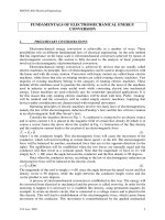
band and holes in the valence band. The representation of energy band for
semiconductor is shown in Fig. 1(a). E
c
and E
v
are designated as the bottom
of the conduction band and the top of the valence band, respectively. The
kinetic energy of electron is measured upward from E
c
, whereas that of hole
is measured downward from E
v
, because a hole has a charge opposite to
electron. The electrons in conduction band and holes in valence band can
contribute to the current flow. On the contrary, in an insulator, the band gap
is so large (E
g
Ͼ 5 eV) that the conduction band is empty even at room tem-
perature. In a conductor, the conduction band is partially filled with electrons
or overlaps the valence band. Consequently, there is no band gap and the
resistivity is very small.
2.1.1. Intrinsic Semiconductor
When electrons and holes generated from impurities are much smaller
than thermally generated electrons and holes, they are called intrinsic semi-
conductors. The number of electrons in the conduction band per unit vol-
ume and that of holes in the valence band per unit volume are represented
as n and p, respectively, and can be derived from the density of state and the
distribution function. The electron concentration in the conduction band is
expressed by
4 T. Soga
E
c
E
c
E
c
E
v
E
v
E
v
E
F
E
F
E
F
(a) (b) (c)
E
g
Fig. 1. (a) Energy band representations of intrinsic semiconductor, (b) extrinsic semi-
conductor with donors and (c) extrinsic semiconductor with acceptors.
nϭϫ()(density of state probability that an electron state iss occupied
top
)dE
E
0
∫
CH001.qxd 11/11/2006 12:16 PM Page 4
where E ϭ 0 means the energy of the bottom of the conduction band and E
top
is the energy of the top of the conduction band. Assuming that the density
of state is equal to 4p(2m
n
/h
2
)
3/2
E
1/2
and the probability of an energy level
being occupied is given by Fermi-dirac distribution function,
n is calculated to be
where E
F
is the Fermi level, k the Boltzmann constant, T the absolute tem-
perature, m
n
the effective mass of the electrons, h the Planck’s constant, and
N
c
the effective density of states of electrons in the conduction band.
Similarly, the number of holes in the valence band can be calculated to be
where m
p
is the effective mass of the holes and N
v
the effective density of
holes in the valence band.
For the ideal intrinsic semiconductor, the number of electrons in the
conduction band is equal to that of holes in the valence band at a moderate
temperature, that is, n ϭ p ϭ n
i
, where n
i
is the intrinsic carrier concentra-
tion. If we take a product of n and p, we get the following equation:
It is obvious that the intrinsic carrier concentration decreases if the band gap
becomes larger. The Fermi level of an intrinsic semiconductor is calculated
to be
Because the second term is much smaller than the first, the Fermi level of
an intrinsic semiconductor lies close to the middle of band gap as shown in
Fig. 1(a).
E
EE
kT
N
N
F
cv v
c
ϭ
ϩ
ϩ
22
ln
np N N e N N e n
vc
EE
vc
EkT
i
v
g
ϭϭϭ
x
/T
/
k
2
np N N e N N e n
vc
EE
kT
vc
E
kT
i
vc
g
ϭϭϭ
Ϫ
2
n
mkT
h
EE
kT
N
EE
kT
ncF
c
cF
ϭϪ
Ϫ
ϭϪ
Ϫ
2
2
2
32
p
⎛
⎝
⎜
⎞
⎠
⎟
⎛
⎝
⎜
⎞
⎠
⎟
⎛
⎝
⎜
⎞
⎠
⎟
/
exp exp
1
1ϩ
Ϫ
e
EEkT
F
/
,
Fundamentals of Solar Cell 5
CH001.qxd 11/11/2006 12:16 PM Page 5
2.1.2. Extrinsic Semiconductor
When electrons and holes generated by impurity are not negligible, the
semiconductor is called extrinsic semiconductor. Let us consider the carrier
concentration in the case of Si. When group V atoms such as phosphorus (P)
are doped as impurity, the phosphorous atom forms covalent bonds with its
four neighboring Si atoms. The fifth electron is bound with P atom very
loosely, and therefore ionized even at room temperature. Consequently,
it becomes a conduction electron with negative charge. In this case, Si
becomes n-type semiconductor and the phosphorous atom is called a donor.
Under complete ionization condition, the electron (majority carrier) con-
centration is expressed as nϭ N
D
, where N
D
is the donor concentration. The
donor is an immobile atom with positive charge. Because the equation
np ϭ n
i
2
is valid for extrinsic semiconductor under a thermal equilibrium,
the hole (minority carrier) concentration is expressed as pϭ n
i
2
/N
D
. The
Fermi level is expressed as
The Fermi level can be controlled by the donor concentration and is close
to the bottom of the conduction band. The schematic energy band represen-
tation of extrinsic semiconductor with donor is shown in Fig. 1(b).
Similarly, when group III atoms such as boron (B) are doped as impu-
rity into silicon (Si), the boron atom forms covalent bonds with its four
neighboring Si atoms. The positively charged conduction hole is created.
This is a p-type semiconductor and the boron atom is called an acceptor.
Under complete ionization condition, the hole (majority carrier) concen-
tration is expressed as pϭ N
A
, where N
A
is the acceptor concentration.
The acceptor is an immobile atom with negative charge. The electron
(minority carrier) concentration is expressed as . The Fermi level
is expressed as
In this case, the Fermi level moves closer to the top of the valence band.
The schematic energy band representation of extrinsic semiconductor with
acceptor is shown in Fig. 1(c).
EEkT
N
N
Fv
v
A
Ϫϭ ln
nnN
iA
ϭ
2
/
EE kT
N
N
cF
c
D
Ϫϭ ln
6 T. Soga
CH001.qxd 11/11/2006 12:16 PM Page 6
2.2. Carrier Transport in Semiconductor
2.2.1. Mobility
The electrons in semiconductor move randomly in all directions by the
thermal energy. After a short distance, the electrons collide with a lattice
atom or an impurity atom, or other scattering center. This scattering process
causes the electron to lose the energy taken from the electric field. The
kinetic energy is transferred to the lattice in the form of heat. The average
time between collisions is called the mean free time, t
c
. The random motion
of electrons leads to the average net displacement to be zero. When a small
electric field E is applied to the semiconductor, the electron experiences a
force ϪqE and gets accelerated toward the opposite direction of the field,
where q is an electric charge (1.6ϫ 10
Ϫ19
C). The velocity component pro-
duced by the electric field is called the drift velocity, v
n
. The change in
momentum of an electron in a mean free time is given by
so that
where m
n
is called electron mobility. Similarly, the hole drift velocity is
expressed by
where m
p
is called hole mobility. The difference of sign is because of the
direction accelerated by the electric field.
2.2.2. Drift Current
Let us consider an n-type semiconductor with a cross-sectional area of
A and a carrier concentration of n as shown in Fig. 2. When an electric field
E is applied to the sample, the electron current density is given by
J
I
A
nqv nq E
n
n
nn
ϭϭϪ ϭm
v
q
m
EE
p
c
p
p
ϭϭ
t
m
v
q
m
EE
n
c
n
n
ϭϪ ϭϪ
t
m
mv qE
nn c
ϭϪ t
Fundamentals of Solar Cell 7
CH001.qxd 11/11/2006 12:16 PM Page 7
where I
n
is the electron current. Similarly, the hole current density is given by
The total current density due to the electric field is known as drift current
density and given by
where s is called conductivity which is reciprocal of resistivity.
We consider the drift current using the energy band diagram. When the
electric field is applied to the semiconductor, as shown in Fig. 3, the gradi-
ent of the conduction band and the valence band takes place and the elec-
trons and holes flow to reduce the potential energy. It should be noted that
the electrons and the holes move toward opposite directions, but the direc-
tion of current is the same.
2.2.3. Diffusion Current
When there is a spatial variation of electron concentration in the semi-
conductor sample, the electrons move from the region of higher concentra-
tion to that of lower concentration. This current is called the diffusion
current. Let us consider the electron concentration with one-dimensional
gradient in x-direction as shown in Fig. 4(a). The electron flows from right
to left, and the electron flow rate per unit area is given by
FD
dn
dx
n
ϭϪ
JJ J nq pq E E
np n p
ϭϩϭ ϩ ϭ()mms
J pqv pq E
pp p
ϭϭm
8 T. Soga
E
Area: A
I
n
+
−
Fig. 2. Semiconductor sample to consider electron current density.
CH001.qxd 11/11/2006 12:16 PM Page 8
where D
n
is called diffusion coefficient of the electron. Therefore, the
diffusion current density of electron is expressed by
JqD
dn
dx
nn
ϭ
Fundamentals of Solar Cell 9
E
v
E
c
+
−
Electric Field
Current
Fig. 3. Drift of electrons and holes in a semiconductor.
x
x
np
(a) (b)
Electron Flow
Current
HoleFlow
Current
Fig. 4. (a) Diffusion of electrons and (b) holes.
CH001.qxd 11/11/2006 12:16 PM Page 9
When the electron concentration increases with x, the electrons diffuse
toward the negative x-direction, resulting in the current flow toward the
x-direction. Similarly, when the hole concentration increases with x, the holes
diffuse toward the negative x-direction. It should be noted that the direction
of current is opposite compared to electron. The diffusion current density by
hole is given by
where D
p
is the diffusion coefficient of hole. When both an electric field and
a concentration gradient are present, the total current density is given by
for electrons and
for holes.
We treated the diffusion and the drift phenomena separately, but there
is a relationship between two phenomena. The diffusion coefficient is
expressed by
which is known as Einstein relation.
2.3. Optical Absorption and Recombination in Semiconductor
2.3.1. Optical Absorption
The energy of a photon is hv, where h is Planck’s constant and v is the
frequency of the light. The relationship between photon energy and the
wavelength l is given by
lm ()
.
m
c
v
hc
hv hv eV
ϭϭ ϭ
1 2398
(
)
D
kT
q
nn
ϭ m
JpqEqD
dp
dx
pp p
ϭϪm
JnqEqD
dn
dx
nn n
ϭϩm
JqD
dp
dx
pp
ϭϪ
10 T. Soga
CH001.qxd 11/11/2006 12:16 PM Page 10