SIMATIC S7-200 One-Hour Primer
Bạn đang xem bản rút gọn của tài liệu. Xem và tải ngay bản đầy đủ của tài liệu tại đây (3.18 MB, 49 trang )
Preface
Installing the hardware
1
Installing the software
2
Basic settings
3
First programming exercise
4
More exercises
5
Appendix
A
SIMATIC S7-200
S7-200
One-Hour Primer
Training Documents
01/2007
A5E01031470-01
Safety Guidelines
This manual contains notices you have to observe in order to ensure your personal safety, as well as to prevent
damage to property. The notices referring to your personal safety are highlighted in the manual by a safety alert
symbol, notices referring only to property damage have no safety alert symbol. These notices shown below are
graded according to the degree of danger.
Danger
indicates that death or severe personal injury will result if proper precautions are not taken.
Warning
indicates that death or severe personal injury may result if proper precautions are not taken.
Caution
with a safety alert symbol, indicates that minor personal injury can result if proper precautions are not taken.
Caution
without a safety alert symbol, indicates that property damage can result if proper precautions are not taken.
Notice
indicates that an unintended result or situation can occur if the corresponding information is not taken into
account.
If more than one degree of danger is present, the warning notice representing the highest degree of danger will
be used. A notice warning of injury to persons with a safety alert symbol may also include a warning relating to
property damage.
Qualified Personnel
The device/system may only be set up and used in conjunction with this documentation. Commissioning and
operation of a device/system may only be performed by qualified personnel. Within the context of the safety notes
in this documentation qualified persons are defined as persons who are authorized to commission, ground and
label devices, systems and circuits in accordance with established safety practices and standards.
Prescribed Usage
Note the following:
Warning
This device may only be used for the applications described in the catalog or the technical description and only in
connection with devices or components from other manufacturers which have been approved or recommended by
Siemens. Correct, reliable operation of the product requires proper transport, storage, positioning and assembly
as well as careful operation and maintenance.
Trademarks
All names identified by ® are registered trademarks of the Siemens AG. The remaining trademarks in this
publication may be trademarks whose use by third parties for their own purposes could violate the rights of the
owner.
Disclaimer of Liability
We have reviewed the contents of this publication to ensure consistency with the hardware and software
described. Since variance cannot be precluded entirely, we cannot guarantee full consistency. However, the
information in this publication is reviewed regularly and any necessary corrections are included in subsequent
editions.
Siemens AG
Automation and Drives
Postfach 48 48
90437 NÜRNBERG
GERMANY
Order No.:
Ⓟ 12/2006
Copyright © Siemens AG 2006.
Technical data subject to change
One-Hour Primer
Training Documents, 01/2007,
3
Preface
Dear S7-200 user,
A programmable controller runs a control program that you create to solve most automation
tasks. The S7-200 Micro PLC can help you win the automation race to improve safety,
quality, and production speed while reducing project costs.
The S7-200 Micro PLC is being used for more and more applications because it combines
power with an attractive price and simple operation.
To make your first steps in the world of S7-200 as simple as possible, we have created a
special Starter Kit.
This One-Hour Primer is intended to teach you the basic skills to be able to use the S7-200
within the shortest possible time.
And now, we wish you a simple and quick start and every success.
Good luck!
Preface
One-Hour Primer
4 Training Documents, 01/2007,
Contents of the S7-200 starter kit
Item Quantity Available
S7-200 CPU 222 AC/DC Relay 1
Input Simulator for CPU 222 1
Software: STEP 7-Micro/WIN V4 1
Output Simulator on mounting rail 1
PC/PPI Programming Cable (USB/RS 485) 1
S7-200 documentation 1
One Hour Primer (including CD with programming exercises) 1
Screwdriver 1
Practice examples for the One-Hour Primer can be found on the STEP 7-Micro/WIN
documentation CD at: \English\Manuals|PrimerEx, or on your Programming Exercises CD.
Safety guidelines
The One-Hour Primer is a quick introduction to the world of S7-200. It is not a substitute for
the
S7-200 Programmable Controller System Manual
. Therefore, you should observe the
instructions given in the
S7-200 Programmable Controller System Manual
, especially the
safety guidelines.
One-Hour Primer
Training Documents, 01/2007,
5
Table of contents
Preface 3
1 Installing the hardware 7
1.1 Assembly and Installation of the Hardware 7
1.2 Details of the S7-200 (CPU 222) 8
1.3 Wiring diagrams for the assembled hardware 9
2 Installing the software 13
2.1 Installing STEP 7-Micro/WIN for the One-Hour Primer 13
2.2 Starting STEP 7-Micro/WIN 14
2.3 Using the Help system 15
3 Basic settings 17
3.1 Connect the communication cable 17
3.2 Configuring the S7-200 communication 18
3.3 Performing the first function test 19
4 First programming exercise 21
4.1 Writing your first program 21
4.2 Opening the first programming exercise 22
4.3 Downloading the first exercise program to the CPU 23
4.4 Function and Test of the first exercise program 24
4.5 Elements of ladder logic (LAD) 25
4.6 Transforming a circuit diagram 26
4.7 Elements of the first exercise program 27
4.8 Status view (online) 28
4.9 Statements 29
5 More exercises 31
5.1 First program modification 31
5.1.1 AND logic operation 31
5.1.2 Inserting a logic gate 32
5.1.3 Entering the operand and testing 33
5.1.4 Deleting a contact or an operand 34
5.2 Second modification to the program 35
5.2.1 OR logic operation 35
5.2.2 Inserting an OR element 36
5.3 Third modification to the program 37
5.3.1 On-delay timer 37
Table of contents
One-Hour Primer
6 Training Documents, 01/2007,
5.3.2 Understanding the on-delay timer function 38
5.3.3 Programming the on-delay timer 39
5.4 Working with projects 40
5.4.1 Programming with symbols 40
5.4.2 Creating a new project 42
5.5 Do you want to learn more? 45
A Appendix 47
A.1 Of bits, bytes and words 47
A.2 Address areas of the S7-200 48
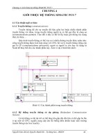
A.3 Cyclic program execution in the S7-200 PLC 49
One-Hour Primer
Training Documents, 01/2007,
7
Installing the hardware
1
1.1 Assembly and Installation of the Hardware
Assembly and Installation of the Hardware
1. Attach the enclosed mounting rail on a base plate as shown here.
Base plate
Mounting rail
2. Attach the enclosed input simulator to the input terminal block located on the bottom of
the S7-200.
Output Simulator
Input Simulator
S7-200
CPU 222
3. Attach the assembled S7-200 to the mounting rail.
4. Attach the output simulator to the mounting rail.
Installing the hardware
1.2 Details of the S7-200 (CPU 222)
One-Hour Primer
8 Training Documents, 01/2007,
1.2 Details of the S7-200 (CPU 222)
Output
terminals
Power
Supply
Mode selector switch-
STOP, TERM, RUN
Connector for
expansion modules
Analog
potentiometer
24 VDC Sensor Power
Supply (180 mA)
Input
Terminals
RS 485
Communications Port
Installing the hardware
1.3 Wiring diagrams for the assembled hardware
One-Hour Primer
Training Documents, 01/2007,
9
1.3 Wiring diagrams for the assembled hardware
Wiring diagram for the assembled hardware
Connect the bold wires as shown in the diagram below. The gray wire is only mechanically
attached to the output simulator. Either end of the gray wire can be connected to L+ or 1L.
!
S7-200 (CPU 222)
6ES7 212-1BB23-0XB0
L1
N
PE
1L Q0.0 0.1 0.2 0.3 PE N L1
1M I0.0 0.1 0.2 0.3 2M 0.4 0.5 M L+
gray
Power supply:
85 to 264 V AC / 47 to 63 Hz
Always connect PE !
gray
Warning
Danger of injury
and material damage.
Ground (blue)
Output
Simulator
On/off
(red)
Direction reversal
(black)
Sensor Supply
Input Simulator
Installing the hardware
1.3 Wiring diagrams for the assembled hardware
One-Hour Primer
10 Training Documents, 01/2007,
Circuit diagram for the assembled hardware
1L Q0.0 0.1 0.2 0.3
S7-200 CPU 222
6ES7 212-1BB23-0XB0
+
M
-
DC 24 V
+
L1
N
PE
1M I0.0 0.1 0.2 0.3 2M 0.4 0.5 0.6 0.7 M L+
PE N L1
24 V inputs (input signals 0 to 24 V DC)
Contacts of the internal
relay outputs
Power supply
85 to 264 V AC/ 47 to 63 Hz
Always connect PE !
Sensor Supply
Output
Simulator
Input
Simulator
Installing the hardware
1.3 Wiring diagrams for the assembled hardware
One-Hour Primer
Training Documents, 01/2007,
11
Wiring diagram of the S7-200 (CPU 222 AC/DC/RLY))
1LN2.01.00.0L1
1M 0.0 0.1 0.2 0.3 2M 0.4 0.5 M L+
+
+
6ES7 212-1BB23-0XB0
CPU 222 AC/DC/RLY (AC Power/DC inputs/Relay outputs)
6 relay outputs Q0.0 to Q0.5
(24 V DC/ 24 to 230 V AC max. 2 A)
Power supply
(85 to 264 V AC)
Output side
Input side
8 inputs I0.0 to I0.7 (24 V DC)
Power supply
24 V DC/ 180 mA
for sensors or expansion modules
One-Hour Primer
Training Documents, 01/2007,
13
Installing the software
2
2.1 Installing STEP 7-Micro/WIN for the One-Hour Primer
In order to install the STEP 7-Micro/WIN V4 programming software you need a PC or
programming device (PG) with a Microsoft Operating System. The software will run on
Windows 2000 Service Pack 3 or later, Windows XP Home, or Windows XP Professional.
1. Insert the CD into your PC or PG that has Microsoft Operating System running.
2. Select the installation.
3. Start the installation wizard and follow the instructions.
1.
2.
3.
Note: If you already have this STEP 7-Micro/WIN version installed, you are prompted to
remove the old software and reboot your system. After the old software is removed, open
and close the CD drive to restart the installation process.
At the end of the installation, the entry, "STEP 7-Micro/WIN" appears in the Windows Start
menu, Start > SIMATIC.
Installing the software
2.2 Starting STEP 7-Micro/WIN
One-Hour Primer
14 Training Documents, 01/2007,
2.2 Starting STEP 7-Micro/WIN
From the Windows Start menu, select the SIMATIC > STEP 7-Micro/WIN V40.4.xx >
STEP 7-Micro/WIN to start the STEP7-Micro/WIN programming software.
Installing the software
2.3 Using the Help system
One-Hour Primer
Training Documents, 01/2007,
15
2.3 Using the Help system
The Help window tabs, Contents, Index, and Find (full text search) help you find a topic
starting with a view of all Help topics.
Select a menu item, or open a dialog box, for which you want help and press the "F1" key to
access the context-sensitive help for that item.
What's This? Help provides definitions of interface elements. You can also access What's
This? Help by pressing the shift and F1 keys simultaneously. The cursor changes to a
question mark; use it to click on the item for which you want help.
If your computer has access to the Internet you can download or retrieve information about
SIMATIC S7-200 hardware and software using the S7-200 on the Web menu item in the
Help menu.
One-Hour Primer
Training Documents, 01/2007,
17
Basic settings
3
3.1 Connect the communication cable
The PC/PPI Programming Cable (USB/RS 485) connects a PC to the S7-200 PLC.
On your PC, use a standard Universal Serial Bus (USB) peripheral connector. Connect the
USB/PPI cable to the PC and the PLC on your PC.
Supply the PLC with the operating voltage.
The STOP or RUN LED should be illuminated.
3*3&
6&38
86%SRUW
Basic settings
3.2 Configuring the S7-200 communication
One-Hour Primer
18 Training Documents, 01/2007,
3.2 Configuring the S7-200 communication
1. Click the communications icon in the navigation bar.
2. Review the communications settings.
3. Double-click the corresponding field to refresh. The connected CPU should now be
recognized and registered automatically.
4. If the CPU is not recognized, or if a pop-up window tells you that communication is not
possible, double-click the field PC/PPI cable.
5. Select PC/PPI cable in the Set PG/PC Interface dialog and select Properties.
6. In the PPI tab, set the station address to 0 and set the transmission rate to 9.6 kbps. In
the Local Connection tab, select the USB port. Click OK to confirm all settings and close
the Properties dialog. Click OK to close the Set PG/PC Interface dialog. Note that the
station address cannot be the same number as the CPU address.
7. Double-click the corresponding field in the communications field to refresh. The CPU will
now be recognized and registered automatically. The process could take a few seconds.
Now click OK to close the Communications dialog.
7.
Basic settings
3.3 Performing the first function test
One-Hour Primer
Training Documents, 01/2007,
19
3.3 Performing the first function test
To perform the first function test, follow the steps below:
1. Set the mode selector of the PLC to the TERM or RUN position. The mode selector is
located behind the small cover at the front side of the CPU.
Note that remote control of the operating mode (RUN or STOP) is possible only in the
TERM or RUN position.
2. From the PC, switch the S7-200 to STOP mode and back to RUN.
The green RUN LED on the PLC lights up in RUN mode. The yellow STOP LED on the
PLC lights up in STOP mode. If you can switch the PLC operating modes from the PC,
the connection between the PC and PLC is configured correctly.
If the mode does not change, check the connecting cable between the PC and PLC and
the communication settings within STEP 7-Micro/WIN.
581
6723
7(50
581
/('581
/('6723
3&33,FDEOHWR
WKH3&
/('6)',$*
One-Hour Primer
Training Documents, 01/2007,
21
First programming exercise
4
4.1 Writing your first program
Great, the first functionality test has been successfully
performed. The controller is up and running and the
data transmission to the PLC works.
But how do I write a program?
Now you will quickly learn how to program the
basic functions of the PLC in small steps using
the small exercise program on the enclosed CD.
First of all, you will learn how to open
an exercise program from the CD
and transfer it to the PLC with the
STEP 7-Micro/WIN programming
software.
After that, you will familiarize
yourself with the function of the
program you have transferred
and test it.
With a little basic knowledge about
“logic operations” you will be able to
analyze the elements of exercise
program 1 and understand the
statements in it.
In the Section “More Exercises” you will
learn the most important knowledge you
require to write your own programs by
changing the exercise program.
Programm
ing
Examples
First programming exercise
4.2 Opening the first programming exercise
One-Hour Primer
22 Training Documents, 01/2007,
4.2 Opening the first programming exercise
1.
2.
Insert the Programming Exercises CD into the CD ROM drive of your PC. This
CD is located in the envelope on the last page of this manual.
. To open the first programming exercise, select File > Open. From the Open window, look in the
CD ROM and open the STEP 7-Micro/WIN project with the appropriate language
(for example, for English: 1hr_pr_en.mwp).
STEP 7-Micro/WIN has now loaded the
programming exercise into the working memory
of the PC and displays the first steps of the
exercise program in the program editor.
CD-ROM Drive
Programming
Examples
First programming exercise
4.3 Downloading the first exercise program to the CPU
One-Hour Primer
Training Documents, 01/2007,
23
4.3 Downloading the first exercise program to the CPU
It is only possible to
transfer a program to the
S7-200 in STOP mode!
Runtime edits are available on the CPU 224, CPU 224XP and CPU 226. Runtime edits allow
program edits while in RUN mode.
You can download the program by following these steps:
With the mode selector in TERM or RUN position, click the Download icon.
The project is automatically compiled. If there are no errors in the project, a
window appears to prompt you to put the PLC back in STOP mode.
Click the OK button in this window to put the PLC in STOP mode. The project is then
downloaded to the PLC.
Once the project has been successfully downloaded to the PLC, a window appears to
prompt you to put the PLC back in RUN mode. Click the YES button to put the PLC back in
RUN mode.
You can also load a program from the PLC onto your programming device/PC.
Click the Upload icon to upload the program from the PLC to the
programming device/PC. It overwrites the program currently displayed on the
monitor. Therefore, you should ensure that you always have a current
version of your program on the hard disc, CD or diskette when you leave a
plant.
First programming exercise
4.4 Function and Test of the first exercise program
One-Hour Primer
24 Training Documents, 01/2007,
4.4 Function and Test of the first exercise program
In the first exercise program, switch S0 turns
the motor on and off. Switch S1 changes the
direction of the motor.
Switches S0 and S1 are the first two
switches on the input simulator. These
switches provide 24 V DC to inputs I0.0 and
I0.1 on the CPU. The output simulator is
connected to Q0.0 and Q0.1 on the CPU.
Q0.0 turns the motor on and off. Q0.1
changes the direction of the motor.
With the exercise program, the signal state
of I0.0 is assigned to output Q0.0 and the
signal state of I0.1 is assigned to Q0.1
24 V DC from Sensor the Power Supply
on the S7-200 CPU
I0.0
Motor
On/Off
I0.1
Change
Direction
Training Simulator
0 V DC from the Sensor Power Supply on the S7-200 CPU
Now let’s test it!
The operating voltage is
connected to the CPU. The
assembly is wired correctly. You
have opened the program exercise
from the CD and downloaded it to
the CPU. The CPU is in RUN
mode (the green RUN LED is on).
Now operate switches S0 and S1
and monitor the results.
Actions
Reactions
Switch S0 operated
Switch S0 & S1
operated
LED I0.0 is on
LEDs I0.0 & I0.1
are on
LED Q0.0 is on
LEDs Q0.0 & Q0.1
are on
Motor turns
Motors turns in the
opposite direction
LEDs I0.0 to I0.7 indicate the signal states
of inputs I0.0 to I0.7.
LEDs Q0.0 to Q0.5 indicate the signal
states of outputs Q0.0 to Q0.5.
I and Q are the customary international
symbols for inputs and outputs (I0.0 Q0.0).
Input SimulatorSwitches S0, S1, S2,
First programming exercise
4.5 Elements of ladder logic (LAD)
One-Hour Primer
Training Documents, 01/2007,
25
4.5 Elements of ladder logic (LAD)
0 and 1 are the only data states in digital control logic. The 0 state is designated as false and
the 1 state is true. This is why we say a PLC scan is either 0 (false) or 1 (true).
()
Schematic
diagram elements
PLC program
ladder diagram elements
Positive logic
Input sensor scan
Is current flowing?
If yes, then the result
of the scan is true
(Result is1)
Negative logic
Input sensor scan:
Is no current flowing?
If yes (no current), then the
result of the scan is true
(Result is 0)
Output Coil:
If the value “true” (current) is
passed to a coil
it is activated
(The coil is ON)
Series circuit connection
(AND logic)
The first switch AND the
second switch must be closed
in order to pass current
Parallel circuit connection
(OR logic )
The first switch OR the second
switch must be closed in order
to pass current
PLC scan
logic elements