SIMATIC NET DP Programming Interface (Cyclic Communication)
Bạn đang xem bản rút gọn của tài liệu. Xem và tải ngay bản đầy đủ của tài liệu tại đây (671.01 KB, 214 trang )
SIMATIC NET
DP Programming Interface (Cyclic Communication)
Manual
C79000-B8976-C071-07
1
Distributed I/Os
2
Characteristics of the DP Programming Interface
3
Basic Principles of Distributed I/Os (DP)
4
Structure of the DP Programming Interface
5
Description of the DP Functions
6
Data Storage
7
Creating DOS Applications
8
Creating Windows Applications
9
Creating Unix Applications
Index
Glossary
Note
We would point out that the contents of this product documentation shall not become a part of or modify any prior or existing
agreement, commitment or legal relationship. The Purchase Agreement contains the complete and exclusive obligations of
Siemens. Any statements contained in this documentation do not create new warranties or restrict the existing warranty.
We would further point out that, for reasons of clarity, these operating instructions cannot deal with every possible problem
arising from the use of this device. Should you require further information or if any special problems arise which are not
sufficiently dealt with in the operating instructions, please contact your local Siemens representative.
General
This device is electrically operated. In operation, certain parts of this device carry a dangerously high
voltage.
WARNING !
Failure to heed warnings may result in serious physical injury and/or material damage.
Only appropriately qualified personnel may operate this equipment or work in its vicinity. Personnel must
be thoroughly familiar with all warnings and maintenance measures in accordance with these operating
instructions.
Correct and safe operation of this equipment requires proper transport, storage and assembly as well as
careful operator control and maintenance.
Personnel qualification requirements
Qualified personnel as referred to in the operating instructions or in the warning notes are defined as persons who are familiar
with the installation, assembly, startup and operation of this product and who possess the relevant qualifications for their work,
e.g.:
−
Training in or authorization for connecting up, grounding or labeling circuits and devices or systems in accordance with
current standards in safety technology;
−
Training in or authorization for the maintenance and use of suitable safety equipment in accordance with current standards
in safety technology;
−
First Aid qualification.
!
DP Programming Interface (Cyclic Communication)
C79000-B8976-C071-07
3
DP Programming Interface
The distributed I/Os (abbreviated to DP from now on) allow you to use a variety of
analog and digital input/output modules with a distributed configuration in close proximity
to the process
There can be large distances between the individual I/O devices bridged by the serial
field bus PROFIBUS. Distributed I/O devices capture the input signals locally and
transfer them via the field bus to the central controller in the programming device/PC. In
the opposite direction, the central controller sends output data to the distributed I/O
devices cyclically.
Networking the components results in a considerable reduction in cabling compared with
previous methods in which the components were “hard” wired.
The PROFIBUS DP protocol used for the distributed I/Os is based on the
communications standard for the field area PROFIBUS EN 50 170 Vol. 2. The concept
of DP communication was developed in a joint venture by leading manufacturers of
programmable logic controllers. It describes a multivendor (heterogeneous) transmission
protocol designed to meet the requirements of the field area. DP communication uses a
subset of the open communications services standardized in EN 50 170.
PROFIBUS DP is intended for time-critical applications. The simple, optimized
transmission protocol, the high transmission rates, and the use of a master-slave
structure achieve short cycle times.
This volume describes the DP protocol and how to program it.
DP Programming Interface
DP Programming Interface (Cyclic Communication)
4
C79000-B8976-C071-07
Contents
DP Programming Interface (Cyclic Communication)
C79000-B8976-C071-07
5
Contents
Note
The table of contents below only includes two levels to preserve clarity.
You will find a detailed table of contents at the beginning of each
chapter.
1 Distributed I/Os...........................................................................................................7
1.1 Description .......................................................................................................8
1.2 DP Protocol......................................................................................................9
2 Characteristics of the DP Programming Interface..................................................11
2.1 Introduction ....................................................................................................12
3 Basic Principles of Distributed I/Os (DP) ................................................................15
3.1 Communication Between the DP Stations.......................................................16
3.2 Data Areas on the DP Master.........................................................................20
3.3 The Modes of the DP Master..........................................................................23
3.4 The Event Messages of the DP Master...........................................................25
3.5 The Operating Status of the DP Slaves..........................................................26
3.6 Control Frames to One or More Slaves ..........................................................27
3.7 Notes on Configuration...................................................................................32
4 Structure of the DP Programming Interface............................................................41
4.1 Overview of the DP Call Functions.................................................................42
4.2 General Call for the DP Functions ..................................................................44
4.3 Evaluating a Function Call..............................................................................45
4.4 Error IDs.........................................................................................................48
4.5 Transfer Structures.........................................................................................52
4.6 Description of the Structure Elements.............................................................54
4.7 Assignment of the Parameters to the DP Functions........................................55
4.8 Constants.......................................................................................................56
4.9 Structure of a DP Application..........................................................................65
5 Description of the DP Functions .............................................................................69
5.1 dpn_init (Logging on a DP Application)...........................................................72
5.2 dpn_wd (Sign of Life Monitoring of the DP Application) ..................................81
5.3 dpn_read_bus_par (Read Bus Parameters) ....................................................84
5.4 dpn_load_bus_par (Write Bus Parameters) ....................................................87
5.5 dpn_read_slv_par (Read Slave Parameters) ..................................................90
5.6 dpn_set_slv_state (Activating/Deactivating a DP Slave).................................93
5.7 dpn_read_cfg (Obtaining the Configuration of the DP System).......................96
Contents
DP Programming Interface (Cyclic Communication)
6
C79000-B8976-C071-07
5.8 dpn_slv_diag (Request Diagnostic Data of a Slave) .....................................100
5.9 dpn_read_sys_info (Obtain Status Information from the DP System)............103
5.10 dpn_out_slv (Send Output Data to a DP Slave)............................................107
5.11 dpn_out_slv_m (Send Output Data to Several DP Slaves) ...........................111
5.12 dpn_out_slv_ext (Send Output Data to Several DP Slaves - Extended
Function)......................................................................................................116
5.13 dpn_read_slv (read local output data of a DP slave).....................................121
5.14 dpn_in_slv (Read Local Input data of a DP Slave)........................................125
5.15 dpn_in_slv_m (Read Local Input data of Several DP Slaves).......................129
5.16 dpn_in_slv_ext (Read Input Data of Several DP Slaves - Extended Function)134
5.17 dpn_set_mode (Set the Mode of the DP Master) ..........................................139
5.18 dpn_get_mode (Query the Mode of the DP Master)......................................142
5.19 dpn_global_ctrl (Acyclic Sending of a Control Frame)...................................145
5.20 dpn_reset (Logging Off a DP Application).....................................................149
6 Data Storage ...........................................................................................................153
6.1 Structure of the Input and Output Data .........................................................154
6.2 Structure of the Diagnostic Data on Standard Slaves....................................156
6.3 Structure of the Diagnostic Data on Non-Standard Slaves............................166
6.4 Structure of the Bus Parameters...................................................................173
6.5 Structure of the Slave Parameters................................................................176
7 Creating DOS Applications....................................................................................185
7.1 Overview......................................................................................................186
7.2 Environment under DOS ..............................................................................187
7.3 Logging on a DP Application.........................................................................189
8 Creating Windows Applications ............................................................................193
8.1 Overview......................................................................................................194
8.2 Environment under Windows........................................................................195
8.3 Logging on a DP Windows Application .........................................................199
9 Creating Unix Applications....................................................................................205
10 Index........................................................................................................................207
11 Glossary..................................................................................................................209
Distributed I/Os
DP Programming Interface (Cyclic Communication)
C79000-B8976-C071-07
7
1 Distributed I/Os
This chapter describes the basic characteristics of the distributed input/output system:
•
Central control by a master
•
High data throughput with a simple transmission protocol
•
Cyclic transmission of the process image in the input/output direction
•
Simple, cost-effective attachment
•
Data transmission via twisted pair (RS 485) or optical fiber
•
Detection of errors with online diagnostics
•
Based on EN 50 170 Vol. 2, it allows parallel operation of FMS (master and slaves)
on one bus.
Contents of Chapter 1
1.1 Description .......................................................................................................8
1.2 DP Protocol......................................................................................................9
Distributed I/Os
DP Programming Interface (Cyclic Communication)
8
C79000-B8976-C071-07
1.1
Description
I/O Devices
from Siemens
A wide variety of I/O devices are available for various applications:
Name Description
ET 200M The ET 200M is a modular I/O device with degree
of protection IP 20 that is expanded by signal
modules designed to be compatible with S7-300
modules.
ET 200B The ET 200B is a small, compact I/O device with a
shallow installation depth and with degree of
protection IP 20.
Numerous analog and digital I/O modules are
available.
ET 200C The ET 200C is a compact I/O device with the high
degree of protection IP 66/IP 67.
ET 200C I/O systems are available with digital and
analog inputs and outputs.
Due to its robust construction, it is particularly
suited for operation in a hostile industrial
environment.
Design and
Installation
For detailed information about the functions, design, and installation of
the I/O devices listed above, refer to the manuals for the particular
product.
Further
Information
Further information about available components and attaching devices
can be found in the SIMATIC NET catalog IK 10.
Distributed I/Os
DP Programming Interface (Cyclic Communication)
C79000-B8976-C071-07
9
1.2
DP Protocol
Basic Design
Figure 1. 1 shows the basic design and components of a PROFIBUS
DP system controlled by one computer with a PROFIBUS CP installed.
DP Master with PROFIBUS CP
PROFIBUS
DP Master/slave communication Master/master communication
Figure 1. 1: Basic Design
Definition of DP
Slave and DP
Master
The PROFIBUS standard EN 50 170 Vol. 2 defines two classes of
stations:
•
passive stations
•
active stations
In the distributed peripheral I/O system, the I/O devices are passive
stations. They are known as
DP slaves
. The DP slaves are controlled
by an active master station. This master station is known as the
DP
master
.
DP Master Class 1 The DP programming interface allows the use of a PROFIBUS CP in a
programming device/PC as a DP master class 1. The PC in
conjunction with the PROFIBUS CP, controls the communication with
the distributed I/O devices and executes the central functions of a DP
master class 1 complying with EN 50 170 Vol. 2, in other words:
•
Initialization of the DP system
•
Parameter assignment/configuration of the DP slaves
•
Cyclic data transfer to the DP slaves
•
Monitoring of the DP slaves
•
Supply of diagnostic information
Distributed I/Os
DP Programming Interface (Cyclic Communication)
10
C79000-B8976-C071-07
Characteristics of the DP Programming Interface
DP Programming Interface (Cyclic Communication)
C79000-B8976-C071-07
11
2 Characteristics of the DP Programming Interface
This chapter provides you with an overview of the characteristics of the DP programming
interface.
The following sections contain more detailed information about using the various
possibilities provided by the interface.
Contents of Chapter 2
2.1 Introduction ....................................................................................................12
Characteristics of the DP Programming Interface
DP Programming Interface (Cyclic Communication)
12
C79000-B8976-C071-07
2.1
Introduction
Overview of
the
Characteristics
The DP programming interface has the following characteristics:
•
Simple linking of a DP application using the functions of the DP
programming interface
•
Multi-level reliability concept
•
Data consistency
•
Support of single-user and multiuser operation
•
Support of single-board and multiboard operation
•
Support of various operating systems and compilers
•
Support of slaves belonging to the ET 200 system
These points are explained in more detail below.
Simple Linking of
DP Applications
The DP programming interface provides you with a range of functions
in the form of a library. All the functions have a uniform structure. They
allow simple access to the functions of the DP master (class 1).
The function calls of the DP programming interface are explained in
detail in Section 5.
Multi-Level
Reliability Concept
The DP programming interface provides a multi-level reliability
concept to limit the effects of the failure on a communication
connection or the DP master.
•
A configurable watchdog for DP slaves ensures that a DP slave that
has not been accessed for a longer period of time changes to a safe
operating mode.
•
An AUTOCLEAR function can be activated so that if individual DP
slaves cannot be accessed, the DP master automatically changes
to the CLEAR state.•
•
A sign of life monitoring function can be activated on the DP master
to detect inactivity of a DP application and to change the DP slaves
controlled by the application to a safe operating mode.
For more detailed information about the watchdog, refer to
Section 3.7.1. The AUTOCLEAR function is described in detail in
Section 3.7.6 and the sign of life monitoring in Section 5.2.
Data Consistency
When transferring the data between the DP slave and DP application,
data consistency is ensured by internal mechanisms.
Characteristics of the DP Programming Interface
DP Programming Interface (Cyclic Communication)
C79000-B8976-C071-07
13
Single-User /
Multiuser
Operation
In single-user operation, only one DP application accesses the DP
programming interface. This is the standard application under DOS.
When using operating systems that permit multitasking (for example
Windows 3.x, Windows 95 and Windows NT), other separate DP
applications can share the DP programming interface. In such
applications, the DP programming interface provides mechanisms for
coordinating the tasks.
Single-Board /
Multiboard
Operation
Single-board operation means that only
one
PROFIBUS CP is
operated in the programming device/PC.
In multiboard operation,
more than one
PROFIBUS CP is operated in
the programming device/PC. Each of these modules is connected to its
own bus. This allows several PROFIBUS DP bus systems to be
controlled from one computer. Each CP is the DP master on its bus.
For detailed information about single-board and multiboard operation
with different operating systems, refer to Chapters 7 and 8.
Operating Systems
and Compilers
The DP programming interface is designed for different operating
systems and compilers.
For detailed information about the supported operating systems,
compilers, memory model, DP library, include files etc., refer to
Chapters 7, 8 and 9.
Characteristics of the DP Programming Interface
DP Programming Interface (Cyclic Communication)
14
C79000-B8976-C071-07
Basic Principles of Distributed I/Os (DP)
DP Programming Interface (Cyclic Communication)
C79000-B8976-C071-07
15
3 Basic Principles of Distributed I/Os (DP)
This chapter explains the basic principles of the DP protocol. Understanding the structure
of communication between the DP master and DP slaves is indispensable for the
efficient use of the function calls of the DP programming interface.
This chapter explains the following:
•
How data is transferred between the DP master and DP slaves
•
How the data structures in the DP master are organized
•
The various modes of the DP master
•
Which events can be signaled to the DP master
•
The various modes of the DP slaves
•
Which control frames the DP master sends to the DP slaves
•
What you should remember when configuring.
Contents of Chapter 3
3.1 Communication Between the DP Stations.......................................................16
3.1.1 Polling............................................................................................................16
3.1.2 Diagnostic Messages......................................................................................18
3.1.3 Parameter Assignment/Configuration .............................................................19
3.2 Data Areas on the DP Master.........................................................................20
3.3 The Modes of the DP Master..........................................................................23
3.4 The Event Messages of the DP Master...........................................................25
3.5 The Operating Status of the DP Slaves..........................................................26
3.6 Control Frames to One or More Slaves ..........................................................27
3.6.1 Cyclic Transmission of Control Frames ..........................................................28
3.6.2 Acyclic Transmission of Control Frames.........................................................31
3.7 Notes on Configuration...................................................................................32
3.7.1 Watchdog.......................................................................................................33
3.7.2 Data Control Time..........................................................................................34
3.7.3 Poll Timeout...................................................................................................35
3.7.4 Min Slave Interval ..........................................................................................36
3.7.5 Deactivating a DP Slave.................................................................................37
3.7.6 AUTOCLEAR .................................................................................................38
3.7.7 Configuration Data .........................................................................................39
Basic Principles of Distributed I/Os (DP)
DP Programming Interface (Cyclic Communication)
16
C79000-B8976-C071-07
3.1
Communication Between the DP Stations
3.1.1 Polling
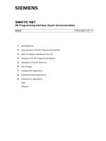
Description
Communication between the DP master and the distributed I/O
stations takes the form of polling. Polling means that in the productive
phase the DP master sends frames to the DP slaves assigned to it
cyclically. Each DP slave is sent its own call frame.•
Call and Receive
Frame
The call frame contains the current output data that the DP slave will
apply to its output ports. If a DP slave does not have output ports, an
“empty frame” is sent instead.
The reception of a call frame must be acknowledged by the addressed
DP slave by returning an acknowledgment frame. The
acknowledgment frame contains the current input data applied to the
input ports of the DP slave. If a DP slave does not have input ports, an
“empty frame” is returned instead.
Figure 3. 1: Schematic Representation of the Polling Mode
Polling Cycle
All the operational DP slaves are addressed in one polling cycle. As
soon as the last slave is addressed, a new polling cycle starts.
This method ensures that the data are up-to-date.
The current input data and diagnostic data of the DP slaves are
available to the DP application on the data interface of the DP master.
The current output values of the DP application are applied to the
output ports of the DP slave.
Basic Principles of Distributed I/Os (DP)
DP Programming Interface (Cyclic Communication)
C79000-B8976-C071-07
17
Note
The DP protocol is optimized for a fast data throughput between
master and slave and does not have flow control between master and
slave. Input and output data are exchanged between the master and
slave cyclically. Note the following points when creating an AP
application:
•
If you modify output data in the data image of the master several
times within the cycle time, some values will not be transferred to
the slaves.
•
If you do not read input data in the data image of the master within
the cycle time, some value changes on the slaves will be lost.
Basic Principles of Distributed I/Os (DP)
DP Programming Interface (Cyclic Communication)
18
C79000-B8976-C071-07
3.1.2 Diagnostic Messages
Signaling
In the acknowledgment frame, a DP slave can not only return the
current input data but also indicate to the DP master that diagnostic
messages are available.
Description
Diagnostic messages inform the DP application that special events or
errors have occurred on the DP slave, such as a short-circuit,
undervoltage, overvoltage, overload, wire break etc.
Reaction
When it receives the diagnostic message, the DP master reads the
diagnostic data using a special call frame and makes this data
available to the DP application.
The diagnostic data have a uniform structure (see Section 6.2). This
allows the DP application to make a detailed error analysis.
Basic Principles of Distributed I/Os (DP)
DP Programming Interface (Cyclic Communication)
C79000-B8976-C071-07
19
3.1.3 Parameter Assignment/Configuration
Requirements
The DP master can only enter a productive data exchange with the DP
slaves when it has assigned parameters to them and configured them.
The master assigns parameters and configures the slaves
•
during the startup phase of the DP master
•
after a temporary failure of a slave during the productive phase.
Parameter
Assignment Frame
The parameter assignment frame sets global operating parameters on
the slave (for example the duration of the watchdog).
Configuration
Frame
Description
The configuration frame is sent after the DP slave has had parameters
assigned to it.
This contains the current configuration of the DP slave. The
configuration contains the number and type of input/output ports.
Reaction
The DP slave compares the received configuration frame with its own
values that it recorded during the startup phase.
If the values match, the DP slave confirms the configuration and
changes to the productive phase.
Configuration
The parameter assignment and configuration data are specified using
the COM PROFIBUS tool.
COM PROFIBUS generates a database with all the relevant parameter
assignment and configuration data.
This database is loaded on the CP during the startup phase.
Basic Principles of Distributed I/Os (DP)
DP Programming Interface (Cyclic Communication)
20
C79000-B8976-C071-07
3.2
Data Areas on the DP Master
Description
For each configured DP slave, the DP master has three different data
areas:
•
input data from the DP slave
•
output data to the DP slave
•
Diagnostic data from the DP Slave
Properties
These areas form a common interface between the CP and the DP
application.
•
They are continuously updated during the productive phase.
•
An internal security mechanism ensures the consistency of the data
if the DP application and field bus access controller access the data
simultaneously.
•
A DP application can access the data areas using various function
calls to the DP programming interface.
Basic Principles of Distributed I/Os (DP)
DP Programming Interface (Cyclic Communication)
C79000-B8976-C071-07
21
Representation of
the Data Areas
Figure 3. 2 shows the data areas of the DP master.
Consistency check Consistency check Consistency check
Input
Output Diagn.
PROFIBUS access control
Data group
Data group
etc.
PROFIBUS
Consistency check Consistency check Consistency check
Input
Output
Diagnostic
Read input
Write output Read diagn.
data
data
data
data
data data
data
data
data
slave 2
slave 1
Figure 3. 2: Data Areas of the DP Master
Output Data
The data in this area are provided by the DP application. In the
productive phase (i.e. after successful parameter
assignment/configuration), they are sent to the DP slave cyclically. If
no output data exist, an “empty frame” is transmitted instead.
Input Data
During the productive phase, the DP slave sends its input data back to
the master in its response frame following each call frame of the DP
master. If the DP slave does not have any input ports, it sends an
“empty frame” instead. The data received as a response are entered in
the input area of the DP master.
Basic Principles of Distributed I/Os (DP)
DP Programming Interface (Cyclic Communication)
22
C79000-B8976-C071-07
Diagnostic Data
If a DP slave recognizes an error during the initialization or productive
phase, it can indicate this to the DP master using a diagnostic request.
The received diagnostic data are entered in the diagnostic area of the
DP master.
Basic Principles of Distributed I/Os (DP)
DP Programming Interface (Cyclic Communication)
C79000-B8976-C071-07
23
3.3
The Modes of the DP Master
Overview
Communication between the DP master and DP slaves involves four
modes:
•
OFFLINE
•
STOP
•
CLEAR
•
OPERATE
Modes
Each of these modes is characterized by defined actions between the
DP master and the DP slaves.
Mode Meaning
OFFLINE There is no DP communication whatsoever between
the DP master and the DP slaves. This is the initial
status of the DP master.
STOP There is also no DP communication between the DP
master and DP slaves in this mode. In contrast to the
OFFLINE mode, a DP diagnostic station (DP master
class
2) can read out diagnostic information of the DP
master.
CLEAR In this mode, the master assigns parameters to and
configures all DP slaves entered in the database and
activated. Following this, the cyclic data exchange
between the DP master and DP slaves begins. In the
CLEAR mode, the value 0h is sent to all slaves with
process output, i.e. the process output is deactivated.
The input data of the slaves are known and can be
read out.
OPERATE The cyclic data transfer to the DP slaves takes place in
the OPERATE mode. This is the productive phase. In
this mode, the DP slaves are addressed one after the
other by the DP master. The call frame contains the
current output data and the corresponding response
frame contains the current input data.
Basic Principles of Distributed I/Os (DP)
DP Programming Interface (Cyclic Communication)
24
C79000-B8976-C071-07
Setting the Mode
Initially, the DP master is in the OFFLINE mode. To change to the
productive phase, in other words to the OPERATE mode, the master
must run through the modes above in the following sequence:
OFFLINE
➜
STOP
➜
CLEAR
➜
OPERATE
The DP programming interface provides two ways in which you can
change the mode:
•
After a DP application has logged on, the DP master changes to the
OPERATE mode automatically (in other words without any further
action by the DP application) and remains in this mode until the DP
application is terminated.
•
After a DP application has logged on, the DP master remains in the
OFFLINE mode. The transition to a different mode is triggered by a
special function call of the DP application, in other words the DP
application itself is responsible for setting the mode.
Which of the two possible methods is used, is specified when the DP
application logs on.
Special Case
"AUTOCLEAR"
Regardless of the methods explained above, you can also specify
during configuration that the DP system changes to a “safe” mode if an
error occurs. This function is known as AUTOCLEAR.
To achieve this reaction, the "Autoclear" option must be set
using the configuration tool.
Effect
If an error occurs on one or more DP slaves during the productive
phase, the DP master changes
automatically
to the CLEAR status
(the DP system is closed down). In the CLEAR status, the DP master
sends data with the value 0h or an empty frame to the DP slaves in the
output direction. The DP master no longer exits this status on its own
initiative, in other words the user must bring about a change to the
OPERATE mode explicitly.
Further
Information
The DP application can recognize the current mode of the DP master
from the return parameters of certain function calls. For more detailed
information about this topic, refer to Section 4.8.3, “Constants of the
Modes“ or Chapter 5, "DP Function Calls“.
☞
Basic Principles of Distributed I/Os (DP)
DP Programming Interface (Cyclic Communication)
C79000-B8976-C071-07
25
3.4
The Event Messages of the DP Master
Overview
During the operating phase, unexpected events can occur that are
significant for the DP application. In this case, the DP master can
inform the DP application of the following events using a return
parameter in response to DP function calls:
Event Message Meaning
Autoclear Automatic closing down of the DP system to the CLEAR mode, when
errors occur in communication with DP slaves.
Requirement:
The AUTOCLEAR function must be configured in
COM PROFIBUS
.
Timeout The watchdog time of the DP application has expired.
Cause:
The DP application has not made a DP function call during the time
preset by the application.
Requirements
The DP application must have logged on and transferred a watchdog
time to the DP master. The required function calls are described in
Chapter
5
.
Access by a DP
master class 2
The DP master class 2 is a special DP diagnostic station that can
perform detailed online diagnostics of the DP master class 1 and DP
slaves. This event message signals that a DP diagnostic station is
taking part in the bus traffic and is currently accessing internal
diagnostic lists of the DP master.
Note:
With the current DP firmware, no special reaction to the event
message is normally required of the DP application since the CP
normally handles data exchange with the diagnostic station
automatically.
The event message is a “place holder” intended for future expanded
diagnostic DP functions in which the DP application will have the
option of coordinating certain diagnostic sequences with the DP
diagnostic station.
Further
Information
With function calls from a DP application, the DP master enters the
event messages in a special return parameter. For detailed information
about the constants occurring in event messages, refer to
Section 4.8.4, and the function calls in Chapter 5.