autonomous robots - modeling, path planning, and control
Bạn đang xem bản rút gọn của tài liệu. Xem và tải ngay bản đầy đủ của tài liệu tại đây (11 MB, 348 trang )
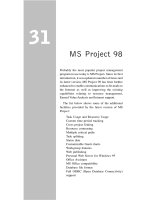
Autonomous Robots
Modeling, Path Planning, and Control
Farbod Fahimi
Autonomous Robots
Modeling, Path Planning, and Control
123
Farbod Fahimi
Mechanical Engineering Department
University of Alberta
Edmonton, Alberta
Canada
ISBN: 978-0-387-09537-0 e-ISBN: 978-0-387-09538-7
DOI 10.1007/978-0-387-09538-7
Library of Congress Control Number: 2008931982
c
Springer Science+Business Media, LLC 2009
All rights reserved. This work may not be translated or copied in whole or in part without the written
permission of the publisher (Springer Science+Business Media, LLC, 233 Spring Street, New York,
NY 10013, USA), except for brief excerpts in connection with reviews or scholarly analysis. Use in
connection with any form of information storage and retrieval, electronic adaptation, computer
software, or by similar or dissimilar methodology now known or hereafter developed is forbidden.
The use in this publication of trade names, trademarks, service marks, and similar terms, even if
they are not identified as such, is not to be taken as an expression of opinion as to whether or not
they are subject to proprietary rights.
Printed on acid-free paper
springer.com
Dedicated to my supportive father, who sacrificed so
much for his children.
Preface
Autonomous Versus Conventional Robots
It is at least two decades since the conventional robotic manipulators have become a
common manufacturing tool for different industries, from automotive to pharmaceu-
tical. The proven benefits of utilizing robotic manipulators for manufacturing in dif-
ferent industries motivated scientists and researchers to try to extend the applications
of robots to many other areas. To extend the application of robotics, scientists had
to invent several new types of robots other than conventional manipulators. The new
types of robots can be categorized in two groups: redundant (and hyper-redundant)
manipulators and mobile (ground, marine, and aerial) robots. These two groups of
robots have more freedom for their mobility, which allows them to do tasks that the
conventional manipulators cannot do.
Engineers have taken advantage of the extra mobility of the new robots to make
them work in constrained environments. The constraints can range from limited
joint motions for redundant (or hyper-redundant) manipulators to obstacles in the
way of mobile (ground, marine, and aerial) robots. Since these constraints usually
depend on the work environment, they are variable. Engineers have had to invent
methods to allow the robots deal with a variety of constraints automatically. A robot
that is equipped with those methods that make it able to automatically deal with
a variety of environmental constraints while performing a desired task is called an
autonomous robot.
Purpose of the Book
There are many books that discuss different aspects of Robotics. However, they
mostly focus on conventional robotic manipulators and at best, add a brief section
to address mobile robots. Recently, the application of autonomous robots (redundant
and hyper-redundant manipulators, and ground, marine, and aerial robots) is finding
its way into industries and even into people’s everyday life. One can mention several
examples such as robotic helicopters for surveillance, aerial photography, or farm
spraying, high-end cars that park themselves, robotic vacuum cleaners, etc. It is
becoming more important that our students learn about autonomous robots and our
vii
viii Preface
engineers have information resources for designing, analyzing, and controlling these
robots.
Since most of the robotic books only deal with conventional robots, nowadays,
students do not have a chance to learn about autonomous robots and engineers who
design autonomous robots have to resort to extracting information from research
literature to design them, which is tedious for them. The present book provides the
theories and methods that are useful for understanding and designing autonomous
robots to students and engineers in a form that is detailed and easy to follow.
The purpose of this book is to familiarize the Mechanical and Electrical Engi-
neering students and engineers with the methods of modeling/analysis/control that
have been proven efficient through research.
Scope of the Book
Similar to the conventional robotic manipulators, the autonomous robots are multi-
disciplinary machines and can be studied from different points of view, i.e., indus-
trial, electrical, mechanical, and controls points of view. Autonomous robots can
also be studied from the Artificial Intelligence point of view. Covering all these
aspects of autonomous robots in one book is almost impossible and each of these
aspects has their own audience. For these reasons, the scope of the present book is
the mechanics and controls of autonomous robots. The book covers the kinematic
and dynamic modeling/analysis of autonomous robots as well as the methods suit-
able for their control.
Level of the Book
This book is useful for last-year undergraduate and first-year graduate students as
well as engineers. The readers should have passed a second year course in Dynamics
and a third year course in Automatic Control (or similar) to be able to fully take
advantage of this book. The mentioned prerequisites are not an obstacle for Me-
chanical or Electrical Engineering students and engineers, since these courses are
offered in ABET (or CEAB for Canadaian higher education) accredited engineering
programs.
Features of the Book
The key feature of the present book is its contents, which have never been gathered
within one book and have never been presented in a form useful to students and
engineers.
• The present book contains the theoretical tools necessary for analyzing the dy-
namics and control of autonomous robots in one place. The topics that are prac-
tical and are of interest to autonomous robot designers have been picked from
advanced robotics research literature. These topics are sorted appropriately and
will form the contents of the book.
Preface ix
• This book presents the theoretical tools for analyzing the dynamics of and con-
trolling autonomous robots in a form that is comprehensible for students and
engineers. The advanced robotics research literature have usually been authored
with the research community in mind. The mathematical notation and the pre-
sentation method of these publications are not easy to understand. These publi-
cations normally lack the necessary details and intermediate steps. The current
book uses a uniform notation, provides the mathematical background of the the-
ories presentred, expands the details, and includes the intermediate steps and
comprehensive examples to ease and accelerate the reader’s comprehension.
• The current book has problems at the end of each chapter. The problems allow the
reader to practice the theories presented in each chapter. The solution to most of
the problems need some computer aided analysis. Some of the longer problems
are more suitable for term projects.
The author hopes that the present book becomes an asset for learning the appli-
cation of dynamics and controls in the field of autonomous robots.
Edmonton, Alberta, Canada Farbod Fahimi
July 2008
Acknowledgments
I would like to thank my dear friend, Dr. Reza N. Jazar, for his support, encourage-
ment, and comments during the time this book was being authored.
xi
Contents
1 Introduction 1
1.1 Redundant Manipulators . . . . 1
1.1.1 Kinematics 1
1.1.2 Redundancy Resolution . . . 1
1.1.3 Use for Redundancy . . . . . . 2
1.1.4 Mathematical Solution Methods . . . 3
1.2 Hyper-Redundant Manipulators . . . . . 3
1.3 Mobile Robots . 5
1.3.1 Common Types . . . 5
1.3.2 Applications of Mobile Robots 7
1.4 Autonomous Surface Vessels 8
1.4.1 Military and Security Applications . 8
1.4.2 Civilian Applications . . . . . 9
1.5 Autonomous Helicopters. . . . 10
1.5.1 ResearchPlatforms 10
1.5.2 Civilian Applications . . . . . 12
1.5.3 Security and Military Applications . 12
1.5.4 Mathematical Models and Methods 13
1.6 Summary 13
2 Redundant Manipulators 15
2.1 Introduction . . . 15
2.1.1 Kinematics of Redundant Manipulators 16
2.2 Redundancy Resolution at the Velocity Level 20
2.2.1 Exact Solutions . . . 20
2.2.2 Approximate Solution Methods . . . 26
2.3 Redundancy Resolution at the Position Level. 30
2.4 Joint Limit Avoidance and Obstacle Avoidance . . . 34
2.4.1 Joint Limit Avoidance (JLA) . . . . . . 34
2.4.2 Obstacle Avoidance . . . . . . 42
2.5 Summary 48
Problems 48
xiii
xiv Contents
3 Hyper-Redundant Manipulators 51
3.1 Introduction . . . 51
3.2 Parameterization of the Backbone Curve . . . . 52
3.2.1 Workspace Considerations 56
3.3 Fitting Methods 57
3.3.1 Constraint Least Square Fitting Method (CLSFM). . . . . . 57
3.3.2 Recursive Fitting Method (RFM) . . 63
3.3.3 ComparisonBetweentheCLSFMandtheRFM 69
3.4 Inverse Velocity Propagation 70
3.4.1 Velocity of a Point on the Backbone Curve . . . . . 70
3.4.2 Linear Velocity of Joints Located on the
Backbone Curve . 74
3.4.3 Joint Angular Velocities. . . 76
3.4.4 Singularity Considerations in Inverse Velocity
Propagation . 77
3.5 Summary 78
Problems 78
4 Obstacle Avoidance Using Harmonic Potential Functions 81
4.1 Introduction . . . 81
4.2 Potential Theory and Harmonic Functions . . . 83
4.2.1 Properties of Harmonic functions . . 83
4.3 Two-Dimensional Harmonic Potential Functions . . 84
4.3.1 Potential of a Point Source or a Point Sink . . . . . 85
4.3.2 PotentialofaUniformFlow 86
4.3.3 Potential of a Line Segment (a Panel) . . 88
4.3.4 Superposition of Potentials 90
4.3.5 Multiple Line Obstacles . . . 93
4.3.6 UniformFlow 98
4.3.7 GoalSink 98
4.4 Two-Dimensional Robust Harmonic Potential Field . . . . . . 102
4.5 Path Planning for a Single Mobile Robot . . . . 105
4.5.1 Algorithm for a Single Robot . . . . . 105
4.6 Path Planning for Multiple Mobile Robots . . . 106
4.6.1 Algorithm for Multiple Robots . . . . 108
4.7 Structural Local Minimum and Stagnation Points . 111
4.8 Three-Dimensional Harmonic Potential Functions 111
4.8.1 UniformFlow 111
4.8.2 GoalSink 112
4.8.3 Spatial Panel . 114
4.9 Three-Dimensional Robust Harmonic Potential Field . . . . . 119
4.10 Path Planning for Aerial Robots or Hyper-Redundant
Manipulators 123
4.10.1 Algorithm for an Aerial Robot . . . . 123
Contents xv
4.11 Summary 126
Problems 127
5 Control of Manipulators 131
5.1 Introduction . . . 131
5.2 Evolving Control Requirements . . . . . 131
5.3 General Dynamic Model . . . . 132
5.3.1 Standard Second-Order Form . . . . . 132
5.3.2 Standard First-Order Form 134
5.4 Position Control . . . . . . . 135
5.5 Trajectory-Tracking Control 139
5.5.1 Feedback Linearization . . . 140
5.5.2 RobustControl 146
Problems 159
6 Mobile Robots 163
6.1 Introduction . . . 163
6.2 Kinematic Models of Mobile Robots . 163
6.2.1 Hilare Mobile Robots . . . . . 163
6.2.2 Car-Like Mobile Robots . . 166
6.3 Trajectory-Tracking Control Based on Kinematic Models . 168
6.3.1 Hilare-Type Mobile Robots . . . . . . . 168
6.3.2 Car-Like Mobile Robots . . 175
6.4 Formation Control for Hilare Mobile Robots . 182
6.4.1 Geometrical Leader-Follower Formation Schemes. . . . . . 183
6.4.2 Design of the l – α Controller 183
6.4.3 Design of the l – l Controller 188
6.5 Dynamics of Mobile Robots 194
6.5.1 Hilare-Type Mobile Robots . . . . . . . 194
6.6 Trajectory-Tracking Control Based on Dynamic Models . . 201
6.6.1 Hilare-Type Mobile Robots . . . . . . . 202
Problems 217
7 Autonomous Surface Vessels 221
7.1 Introduction . . . 221
7.2 Dynamics of a Surface Vessel. . . . . . . 222
7.3 The Control Point Concept for Underactuated Vehicles . . . 225
7.3.1 TheRoleoftheControlPoint 225
7.4 Zero-Dynamics Stability for a Surface Vessel 226
7.4.1 Stability in Case of General Motions with
Constant Speed . . 228
7.4.2 Equilibrium Point for Circular and Linear Motions
with Constant Speed . . . . . 229
7.4.3 PermissiblePracticalMotions 230
xvi Contents
7.5 Trajectory-Tracking Controller Design . . . . . . 230
7.5.1 The Input–Output Relations . . . . . . 231
7.5.2 Feedback Linearization . . . 232
7.5.3 RobustControlUsingtheSlidingModeMethod 237
7.6 FormationControlforSurfaceVessels 244
7.6.1 Geometrical Leader-Follower Formation Schemes. . . . . . 244
7.6.2 Design of the l – α Controller 245
7.6.3 Design of the l – l Controller 252
7.6.4 ImplementationNotes 256
7.7 Summary 260
Problems 260
8 Autonomous Helicopters 263
8.1 Introduction . . . 263
8.2 A 6-DOF Dynamic Model of a Helicopter . . . 264
8.3 Position Control for Autonomous Helicopters 267
8.3.1 TheHoverTrimmingAngles 268
8.3.2 TheLongitudinalandLateralControlLaw 270
8.3.3 The Latitude and Altitude Control Law . 271
8.4 The Control Point Concept for Underactuated Vehicles . . . 275
8.4.1 TheRoleoftheControlPoint 276
8.5 Robust Trajectory-Tracking Control for Autonomous Helicopters . 277
8.5.1 The Input–Output Equations . . . . . . 278
8.5.2 RobustControlUsingtheSlidingModeMethod 280
8.6 Leader-Follower Formation Control for Autonomous Helicopters. . 287
8.6.1 Formation Control Schemes . . . . . . 289
8.6.2 DesigningtheSlidingModeControlLaw 300
Problems 312
A Mathematics 319
A.1 Null Space 319
A.2 Rank 320
A.3 Singular Value Decomposition (SVD) . . . . . . . 320
A.3.1 ComputingSVD 321
A.4 Pseudo-Inverse for a Rectangular Matrix . . . . 323
A.5 BisectionMethod 323
B Control Methods Review 325
B.1 Feedback Linearization . 325
B.2 SlidingModeControl 326
References 331
Index 337
Acronyms
2D Two-Dimensional
3D Three-Dimensional
ASV Autonomous Surface Vessel
AUSVI Association for Unmanned Vehicle Systems Internatioanl
CLSFM Constraint Least Square Fitting Method
DOFs Degrees of Freedom
GMRES Generalized Minimum RESidual
GPS Global Positioning System
HVAC Heating, Ventilating, and Air Conditioning
IMU Inertial Measurement Unit
JLA Joint Limit Avoidance
P Prismatic
PD Proportional-Derivative
PID Proportional-Integral-Derivative
R Revolute
RFM Recursive Fitting Method
SOI Surface of Influence
SPDM Special Purpose Dexterous Manipulator
SVD Single Value Decomposition
UAV Unmanned Aerial Vehicle
UGV Unmanned Ground Vehicle
USV Unmanned Surface Vessel
WITAS Wallenberg laboratory for research on Information Technology and Autonomous
Systems
xvii
Chapter 1
Introduction
1.1 Redundant Manipulators
1.1.1 Kinematics
A kinematically redundant manipulator is a serial robotic arm that has more
independently driven joints than are necessary to define the desired pose (position
and orientation) of its end-effector. With this definition, any planar manipulator (a
manipulator whose end-effector motion is restrained in a plane) with more than
three joints is a redundant manipulator. Also, a manipulator whose end-effector can
accept a spatial pose is a redundant manipulator if it has more than six independently
driven joints. For example, the manipulator shown in Fig. 1.1 has two 7-DOF arms
mounted on a torso with three degrees of freedom (DOFs). This provides 10 DOFs
for each arm. Since the end-effector of each arm can have a spatial motion with six
DOFs, the arms are redundant. The degree of redundancy of each arm is four, which
is the difference between the joint number and the end-effector’s DOF for the arm.
It should be noted that kinematic redundancy as defined above should not be
confused with actuator or sensor redundancy. Actuator or sensor redundancy is
present if a manipulator has two actuators or sensors on one joint that serve the
same purpose. Actuator or sensor redundancy is introduced in a manipulator design
to increase the fault tolerance and reliability of the design. The kinematics of a
manipulator with redundant actuators or sensors can be treated similar to that of
a conventional manipulator, whereas the kinematics of a kinematically redundant
manipulator must be studied differently.
1.1.2 Redundancy Resolution
For a conventional manipulator, for which the end-effector DOF is equal to the
number of joints, the position/velocity of the joints can be found easily if the
position/velocity of their end-effector is specified. This process is called the “inverse
kinematics” solution. This can be done because the number of equations written
for the pose of the end-effector is exactly equal to the number of unknowns, i.e.,
F. Fahimi, Autonomous Robots, DOI 10.1007/978-0-387-09538-7 1
C
Springer Science+Business Media, LLC 2009
1
2 1 Introduction
Fig. 1.1 A 17-DOF redundant manipulator with two serial arms (Courtesy of Robotics Research
Corporation, Cincinnati, Ohio, USA)
joints’ positions/velocities. For a redundant manipulator, however, there are more
unknowns (joints’ positions/velocities) than there are equations (DOF of the end-
effector). Therefore, the inverse kinematics mathematical problem does not have a
unique solution. There is a need for approaches that can address this mathematical
problem with multiple solutions. These approaches that solve the inverse kinemat-
ics problem for a redundant manipulator are called the “redundancy resolution”
methods.
1.1.3 Use for Redundancy
These multiple solutions allow for a higher task flexibility for a redundant manip-
ulator compared to a conventional manipulator. The resources (structural strength,
force/torque output abilities, extra DOFs, joint accuracies) of a redundant manip-
ulator can be used optimally according to the task at hand. Since there are several
joint configurations for which the end-effector of a redundant manipulator can reach
1.2 Hyper-Redundant Manipulators 3
a certain desired pose, the manipulator can pick the one that serves an extra purpose
better through optimization. Examples of extra purposes are numerous. The manip-
ulator can choose the solution that best transmits force/torque to the end-effector.
Or it can maximize joint range availability by choosing the solutions for which the
joints’ positions are closest to their center positions. The manipulator can pick the
solution that requires the least amount of motion to minimize the joint velocities
or the consumed energy. It can maximize dexterity by selecting the solution that
avoids singularities. The manipulator can choose the solution that maximizes the
structural stiffness to reduce the deflection errors. The extra solutions can be used
by the manipulator to avoid obstacles that would otherwise prevent the end-effector
from reaching its desired pose. The redundant manipulator can reallocate resources
to compensate for the loss of a mechanical degree of freedom.
1.1.4 Mathematical Solution Methods
There are several mathematical solution approaches that allow a redundant manip-
ulator to automatically take advantage of its redundancy to satisfy extra tasks pre-
viously discussed. These mathematical methods can provide the manipulator with
some degree of “autonomy,” such that the manipulator is able to decide on the best
kinematic solution according to the different environmental constraints defined for
it. These methods are discussed throughly in Chapter 2.
The methods introduced in Chapter 2 provide the time history of the joint mo-
tions with which a desired task can be accomplished. However, since these methods
are only kinematic methods, they cannot provide the means for driving the joint
such that the desired task is physically performed by the robot. There are needs
for control methods that can guarantee the physical performance of a manipulator.
These control methods are presented in Chapter 5.
1.2 Hyper-Redundant Manipulators
Hyper-redundant manipulators are kinematically redundant manipulators that have
a very large degree of redundancy. These manipulators have a morphology and oper-
ation analogous to that of snakes, elephant trunks, and tentacles. There are a number
of very important applications where such robots would be advantageous. Working
in cluttered environments and in tight and tunnel-like spaces are the most important
features of hyper-redundant manipulators. Due to having their numerous DOFs and
small link lengths, hyper-redundant manipulators are able to reach inside pipelines
and ducts for repair or inspection. Their key applications are inspection, repair, and
maintenance of mechanical systems related to nuclear reactors [9]. Two snake-like
hyper-redundant manipulators are shown in Fig. 1.2.
Another unique feature of hyper-redundant manipulators is their grasping ability.
Because of numerous DOFs, the flexibility of the hyper-redundant manipulators
4 1 Introduction
Fig. 1.2 Two snake-like hyper-redundant robots
Source: />allows them to grasp objects with various sizes and shapes easily. A typical hyper-
redundant manipulator can grasp a large range of sizes and shapes. If conventional
grippers found on nonredundant manipulators are used to cover the same range of
sizes and shapes of objects, several different grippers will be required.
Hyper-redundant manipulators have been the focus of investigation of many
researchers for nearly 20 years. However, they are mostly still in the laboratory
research phase. There might be a number of reasons for this. The previous kine-
matic modeling techniques, used extensively for redundant manipulators and to
be discussed in Chapter 2, are not suitable to or efficient enough for the needs of
hyper-redundant robot task modeling. This is because the computational cost of the
methods suitable for redundant manipulators is related to the degree of redundancy
of the manipulator, and for a hyper-redundant manipulator with a large degree of
redundancy, the computation cost of these methods become prohibitive. Also, the
complexity of the mechanical design and implementation of hyper-redundant robots
might have prevented their commercialization.
The material of Chapter 3 is meant to present efficient and straight forward re-
dundancy resolution methods specific to hyper-redundant manipulators, to reduce
the burdon of the kinematic computations to an acceptable level for real implemen-
tations. In Chapter 3, the history of joint motions that are required for a given task to
be successfully performed is found. In Section 4.10, a spatial path planning method
is presented that generates three-dimensional (3D) paths among obstacles. These
3D paths can be used as backbone curves for the hyper-redundant manipulators for
obstacle avoidance in a spatial environment. In Chapter 5, controllers are introduced
that use the desired trajectory of joint motions to calculate and apply driving forces
or torque at the joints such that the physical motion can take place.
1.3 Mobile Robots 5
1.3 Mobile Robots
1.3.1 Common Types
There are two common types of mobile robots that have well-designed kinematic
drive chains, which reduce the chances of slip at the wheels of the robot. The two
mobile robot types are Hilare-type and car-like mobile robots. Hilare-type robots
have two independently driven wheels as the drive mechanism and are usually bal-
anced by a passive caster wheel. They have good maneuvering abilities, e.g., a zero
minimum turn radius, and are easier to control. They are also easier to build due to
their simple drive mechanism. The Hilare-type mobile robots have different sizes
and shapes depending on their application. Figure 1.3a shows a Hilare mobile robot
with applications in industries, research, hospitals, and offices. Figure 1.3b shows
another Hilare mobile robot used as an automated waiter. Figure 1.4 shows a robotic
vacuum cleaner of Hilare type.
The Hilare-type mobile robots can have different sizes and shapes; however,
since they share the same drive mechanism, their mathematical models are similar in
structure. For example, the models, introduced in Chapter 6, can simply be adjusted
to be useful for any Hilare-type mobile robot by using the physical parameters in
the model corresponding to the robot, as long as the modeling assumptions are still
valid.
Car-like mobile robots, as their name implies, have a drive mechanism similar to
that of cars. They are driven by a single motor that powers a differential, which in
turn distributes the motor’s torque to the rear wheels. They have a steering mecha-
nism at the front wheel(s), which is driven by a motor to generate steering angles
a)
b)
Fig. 1.3 Hilare type-robots; (a) surveillance robot, (b) automated waiter
Source: (a) />Image:Seoul-Ubiquitous
Dream 11.jpg
6 1 Introduction
Fig. 1.4 A robotic vacuum cleaner
Source: />Discovery.jpg
to steer the robot. An indoor small car-like mobile robot can be seen in Fig. 1.5.
An outdoor mobile robot, developed for the 2007 DARPA Urban Challenge, a com-
petition in which robotic ground vehicles had to drive autonomously in an urban
situation, is shown in Fig. 1.6.
Fig. 1.5 A car-like robot (Courtesy of Neurotechnologija, Vilnius, Lithuania)
1.3 Mobile Robots 7
Fig. 1.6 A car-like robot developed by Team ENSCO for 2007 DARPA Urban Challenge
Source: />1.3.2 Applications of Mobile Robots
Mobile robots have several applications in industries and factories. One can name
transporting parts between gantries, conveyors, air tubes and other processes, trans-
portation among non sequential processes, long-distance deliveries along winding
and trafficked paths, and individualized item positioning at designated stations as
the most common applications of mobile robots in industrial settings.
Many mobile robots are employed for environmental monitoring and inspection.
Application examples are monitoring Heating, Ventilating, and Air Conditioning
(HVAC) effectiveness, watching for hazards such as air quality, radon, radiation and
smoke, checking on buildings and inspect trouble sites remotely to reduce emer-
gency site visits, monitoring wifi reception and sniff for problem spots, and sending
for supplies and equipment from a partner on the other side of the building. A mobile
robot equipped with a closed circuit television can be used to detect intrusion and
hazard in a building.
Mobile robots can be used as automated home helpers. Some of the robots that
can be bought ready-made can map the environment where they are going to work
by driving around randomly or via remote control. They can use this map to travel
to any given point in the mapped environment and avoid obstacles in their way.
The mapping feature of mobile robots are not only useful for the robot navigation,
but are also accurate enough to be used as the measurement of an area. They can
reproduce the actual shape of a room independent of the geometry of the room. They
can follow people around and can vocally communicate with people if their path is
8 1 Introduction
completely blocked! They can serve food on a tray or carry drinks in their mobile
refrigerator.
Security and surveillance is another application of mobile robots. They can watch
for intruders to a secure remote site or a vacation home and vocally issue warnings if
they encounter intruders. They can be scheduled to move around and take snapshots
as they move and send the snapshots to a designated receiver.
To perform the above mentioned functions, a mobile robot must be able to sense
the environment boundary and obstacles, decide how to move from some point to
the other (motion planning), and finally, control its driving mechanism such that the
planned motion is actually executed in reality. Some of the more common theories
and methods for motion planning and control of the two common types of mobile
robots, Hilare-type and car-like, are introduced in Chapters 4 and 6.
1.4 Autonomous Surface Vessels
An autonomous surface vessel (ASV) is a robotic boat or ship that can react to the
environmental changes and accomplish a task with minimum human interference.
Similar to many advanced systems that have civilian use today, the ASVs devel-
opment started for military applications. An unmanned surface vessel is shown in
Fig. 1.7.
1.4.1 Military and Security Applications
One of the military applications of ASVs is reconnaissance and surveillance in the
open ocean and coastal waters. ASVs can furnish situational awareness to remote
command stations in real-time. ASVs operate via remote control from a command
center on a ship, or a plane, or on land, or autonomously. They can send pictures,
video, and other electronic data to a land-based, airborne, or ship-based command
center. ASVs can be powered by diesel engines, electric motors, or even with wind
Fig. 1.7 Silver Marlin unmanned surface vessel with autonomous obstacle avoidance, manufac-
turered by Elbit Systems (Courtesy of Oreet International Media Ltd.)
1.4 Autonomous Surface Vessels 9
power. They can be designed for speed and can perform over the horizon, long-
duration missions.
The ASVs are usually equipped with suites of ocean surveillance equipment,
for example, stabilized infrared, thermal imaging, and live video cameras. These
devices are uplinked with satellite or line-of-sight radio to transmit information to
a control platform in real-time. There is no personnel on-board of ASVs. There-
fore, they can intercept the targets of interest with minimal human and financial
resources, freeing more expensive vessels, helicopters or aircraft for other mission
assignments.
Autonomous Surface Vessels can play an important role in homeland security,
drug control, and search and rescue missions. ASVs can patrol coastal waters, ports,
and sensitive facilities and surveil for law enforcement and drug trafficking control.
By cooperation with manned or unmanned aerial vehicles, ASVs can closely ob-
serve suspicious activities in important maritime locations and passages and issue
early warning of any hostile or illegal activity to a command center. ASVs can pro-
tect the sovereignty of the remote lands with environmental resources. Groups of
ASVs can be used for a long and tiring search and rescue missions.
The ASVs can replace the manned vessels that work in hazardous and dangerous
situations. For example, during torpedo or missile exercises, and gun shoots, the
safety and security of the areas downrange of the test must be ensured. Doing this
using manned vessels, helicopters, or aircraft puts the humans in danger. ASVs can
do this job without any risk to humans. They can be equipped and programmed for
checking the target areas for unauthorized vessels, as well as endangered marine
species. The ASV can provide real-time videos and collect other required data by
being accurately positioned near intended weapon impact points. This eliminates
the risk to personnel or more expensive observation platforms.
Another application for ASVs is providing mine countermeasures. The areas that
are cleared from mines must be monitored to make sure that new mines are not
re-seeded. Because of their small size and draft, undetectable electronic and noise
footprint, and minimal effect on the radar, ASVs are highly suitable for monitoring
sensitive areas such as channels, harbor entrances, and seashore. Such missions do
not risk on-board personnel, since the ASV is unmanned.
1.4.2 Civilian Applications
One can think of many civilian applications for ASVs. Examples are protection of
maritime industrial assets and valuable shipments, protecting platforms for undersea
gas exploration, ocean survey and mapping, metrological data collection, fishery
support, marine biological research, and even recreational boating.
Open-sea operations are conducted by many commercial industries, who have
many valuable mobile (container ships or oil tankers) or stationary assets (piplines
on the sea bottom and off-shore oil rigs). ASVs can surveil the shipping lanes, bot-
tlenecks, and sensitive areas for the mobile assets and can monitor the security of
10 1 Introduction
areas both close and far from the stationary assets. These applications rely on the
advanced sensors that can be mounted on an ASV to provide real-time images and
sensory information and can make a control center aware of any threats.
The ASVs can benefit the undersea oil and mineral exploration in many ways.
The topographical mapping of the ocean floor, which is the beginning of any ex-
ploration before excavation, is done by using sound waves. The mapping demands
strict adherence to a predetermined course by the surface vessel. The ability of pre-
cise navigation for ASV make them a perfect tool for topographical mapping. Also,
ASVs can stay stationary at a given point for an extended period of time without the
need to be anchored or tethered. This feature allows an ASV to be used as a mo-
bile weather buoy for collecting weather and hydrological data, and for supporting
oceanographic investigations.
Fishery Support or compliance can be another application for ASVs. They can be
equipped with sonar sensors and deployed to search for areas with higher population
of fish. After locating the fish, ASVs can direct fishing vessels to the more fish-
populated areas. Equally, ASVs can be used for surveillance in the areas where
fishing is prohibited for protection of the ecosystem and inform the authorities if
illegal fishing activities are recognized.
To design and deploy ASVs, several subsystems must be designed and the sub-
systems must be integrated. Examples of these subsystems are the different sensory
systems needed for different applications of the ASV, the structural and dynamic
stability, the engine and the driveline, the autonomy for independently making deci-
sions, and the controls that actually make the ASV perform its task as planned. Some
part of the autonomy of an ASV that relates to path planning can be addressed by
using the methods introduced in Chapter 4, especially the two-dimensional (2D)
obstacle avoidance method. The nonlinear controls applicable to an ASV is intro-
duced in Chapter 7. Since many applications discussed in this subsection can be
accelerated by using multiple ASVs, some part of Chapter 7 is dedicated to forma-
tion control, with which a group of ASVs can move together with user-specified
distances for accomplishing a cooperative task.
1.5 Autonomous Helicopters
1.5.1 Research Platforms
Several aspects of the autonomy for autonomous helicopters have been and are
still under active research in universities and research centers. Since a real-size
helicopter can be very expensive to purchase, maintain, and fly, most researchers
have developed their own experimental platforms. These platforms are usually de-
veloped by adoption of remote control small-size model helicopters that are avail-
able for hobbyists and aerial photographers. The adapted platform is then modified
and equipped with navigational sensors (GPS receivers, accelerometers, rate gy-
ros, electronic compasses, etc.) and on-board embedded control computers. Some
1.5 Autonomous Helicopters 11
researchers, on the other hand, have used the commercially available model heli-
copters that are ready for autonomous flight. Some of these helicopters had been
used for crop spraying in Japan via remote control. Autonomous helicopters bought
from companies are usually several times more expensive than the cost of the in-
house development of autonomous helicopters with the same size and specifica-
tions. There are also some commercial platforms specifically developed for military
applications (Fig. 1.8).
Several projects for development and experimentation with autonomous model
helicopters started in the 1990s and is continuing still. Several autonomous heli-
copter projects were carried out in the University of Southern California (USC)
since 1991. The USC presented prototypes for Autonomous Vehicle Aerial Track-
ing and Retrieval/Reconnaissance (AVATAR) in 1994 and 1997. The AVATAR
was ranked first in the Association for Unmanned Vehicle Systems International
(AUSVI) robotics competition in 1994.
Some in-house made and commercially available autonomous helicopter plat-
forms have been modified and used by the Carnegie Mellon’s Robotics Institute.
Their autonomous helicopter succeeded to achieve the first place in the AUSVI’s
specialized aerial robotic competition. The AeRobot project, (BEAR in short), at
the University of Berkeley is one of the famous autonomous helicopter projects. The
BEAR team has used their autonomous helicopter as a test platform for evaluating
the feasibility and performance of their integrated approach to intelligent systems.
In the last several years, many aerial robots and autonomous helicopter platforms
have also been designed and built by the Unmanned Aerial Vehicle (UAV) research
facility in the Georgia Institute of Technology (GIT). The GIT also achieved the first
ranking in the AUVSI’s specialized aerial robotics competition.
Fig. 1.8 MQ-8B unmanned helicopter used by the US Marine Corps and the US Navy, manufac-
turered by Northrop Grumman
Source: />Fire Scout.jpeg
12 1 Introduction
Many European research centers work on autonomous helicopters and aerial
robots. The Wallenberg laboratory for research on Information Technology and
Autonomous Systems (WITAS) has had collaborative projects with private com-
panies on UAV research, in which commercial autonomous helicopters have been
used. Furthermore, many European Universities have adapted the conventional radio
controlled helicopters for experimention on coordination and control of multiple
heterogeneous vehicles. One can name the Universidad Polit’cnica de Madrid and
the Technical University of Berlin for their autonomous helicopter platforms, whose
helicopter won the AUSVI’s aerial robotics competitions in 2000.
1.5.2 Civilian Applications
Unmanned small-size helicopters already have numerous civilian applications. These
unmanned, helicopters are mostly remotely controlled, especially for take-off and
landing. However, they extensively use computer-controlled mode for stabilization
of the helicopter in hover and near hover maneuvers. Although the unmanned heli-
copters used for commercial applications are not autonomous (computer-stabilized
would be a more accurate term), in the future, they will take advantage of the re-
search being done about autonomy to accomplish their tasks easier and more accu-
rately. Some of these applications are presented below.
Perhaps aerial photography and videography is the most common application of
unmanned helicopters. The customers of such a service are as follows: real estate
agencies who need the aerial photographs and videos of estates for promotional
purposes and for providing virtual tours of inaccessible sites; publishers who use
pictures of landscapes, bridges, tall buildings, etc., in their publications; movie com-
panies who can film stunts and overhead angles with much lower cost than that of
using a full-size helicopter; news companies who can use them for traffic monitoring
and aerial coverage of news events.
Another common application of unmanned helicopters are for inspection and
security. Regular aerial survey of properties, aerial inspection of bridges, utility
towers, powerlines, piplines, rail roads, and structures are examples of the use of un-
manned helicopters. Furthermore, the unmanned helicopters are used for search and
rescue missions for natural disaster survivors, surveillance of sensitive suspected
areas for criminal activities, and patrolling political boarders for suspicious traffics.
They can be used for remote sensing and monitoring of biological, chemical, and
nuclear weapons.
The aerial robots have some agricultural applications such as crop dusting, crop
health monitoring, and mapping using infrared cameras. They can be used for car-
rying supplies from ground to higher floors, providing temporary and immediate
platforms for communications, and for delivering mail to remote areas.
1.5.3 Security and Military Applications
Drug control and search and rescue missions are ideal applications for autonomous
helicopters. Autonomous helicopters can patrol boarders, ports, and sensitive