Hướng dẫn cài và sử dụng phần mềm Mach3 cho máy CNC Mach3Mill install config
Bạn đang xem bản rút gọn của tài liệu. Xem và tải ngay bản đầy đủ của tài liệu tại đây (4.1 MB, 106 trang )
Mach3 CNC Controller
Software Installation and
Configuration
Version 3
Copyright © 2003, 2004, 2005, 2006, 2008 ArtSoft USA. All Rights Reserved.
The following are registered trademarks of Microsoft Corporation: Microsoft, Windows. Any other trademarks
used in this manual are the property of the respective trademark holder.
Please send queries, comments, complaints, corrections, and suggested improvements for this manual to:
The Mach Developer Network (MachDN) is currently hosted at
.
Printed November 6, 2008
iii
Contents
Chapter 1 Introduction to CNC Systems
Before You Begin . . . . . . . . . . . . . . . . . . . . . . . . . . . . . . . . . . . . . . . . . . . . 1-1
1.1 Introduction . . . . . . . . . . . . . . . . . . . . . . . . . . . . . . . . . . . . . . . . . . . . . . . . . . . . . . . . . . . . . 1-2
1.2 Components of a CNC Machining System . . . . . . . . . . . . . . . . . . . . . . . . . . . . . . . . . . . . . 1-2
1.3 How Mach3 Fits In . . . . . . . . . . . . . . . . . . . . . . . . . . . . . . . . . . . . . . . . . . . . . . . . . . . . . . . 1-4
1.4 What Mach3 Can Do . . . . . . . . . . . . . . . . . . . . . . . . . . . . . . . . . . . . . . . . . . . . . . . . . . . . . . 1-4
Chapter 2 Installing the Mach3 Software
2.1 Installation . . . . . . . . . . . . . . . . . . . . . . . . . . . . . . . . . . . . . . . . . . . . . . . . . . . . . . . . . . . . . . 2-1
2.1.1 Downloading . . . . . . . . . . . . . . . . . . . . . . . . . . . . . . . . . . . . . . . . . . . . . . . . . . . . . . . . . 2-1
2.1.2 Installing . . . . . . . . . . . . . . . . . . . . . . . . . . . . . . . . . . . . . . . . . . . . . . . . . . . . . . . . . . . . 2-1
2.1.2.1 If a machine tool is connected, disconnect it now. . . . . . . . . . . . . . . . . . . . . . . . . . 2-1
2.1.2.2 Run the Mach3 software installation package. . . . . . . . . . . . . . . . . . . . . . . . . . . . . 2-2
2.1.2.3 If You’re Using Windows Vista . . . . . . . . . . . . . . . . . . . . . . . . . . . . . . . . . . . . . . . 2-4
2.1.3 The Vital Reboot . . . . . . . . . . . . . . . . . . . . . . . . . . . . . . . . . . . . . . . . . . . . . . . . . . . . . . 2-4
2.2 Testing The Installation . . . . . . . . . . . . . . . . . . . . . . . . . . . . . . . . . . . . . . . . . . . . . . . . . . . . 2-4
2.2.1 If You Are Using the Default Parallel Port Driver . . . . . . . . . . . . . . . . . . . . . . . . . . . . 2-5
2.3 Mach3 Profiles . . . . . . . . . . . . . . . . . . . . . . . . . . . . . . . . . . . . . . . . . . . . . . . . . . . . . . . . . . . 2-7
2.3.1 Creating a Profile . . . . . . . . . . . . . . . . . . . . . . . . . . . . . . . . . . . . . . . . . . . . . . . . . . . . . . 2-7
2.4 Installation Problems . . . . . . . . . . . . . . . . . . . . . . . . . . . . . . . . . . . . . . . . . . . . . . . . . . . . . . 2-9
2.4.1 Running DriverTest After a Mach3 Crash . . . . . . . . . . . . . . . . . . . . . . . . . . . . . . . . . . 2-9
2.4.2 Manual Driver Installation and Uninstallation . . . . . . . . . . . . . . . . . . . . . . . . . . . . . . . 2-9
Chapter 3 Introducing the Mach3 Screens and Com-
mands
3.1 Screens . . . . . . . . . . . . . . . . . . . . . . . . . . . . . . . . . . . . . . . . . . . . . . . . . . . . . . . . . . . . . . . . . 3-1
3.1.1 Types of Objects on Screens . . . . . . . . . . . . . . . . . . . . . . . . . . . . . . . . . . . . . . . . . . . . . 3-2
3.1.2 Using Buttons and Shortcuts . . . . . . . . . . . . . . . . . . . . . . . . . . . . . . . . . . . . . . . . . . . . . 3-3
3.1.3 Data Entry to DROs . . . . . . . . . . . . . . . . . . . . . . . . . . . . . . . . . . . . . . . . . . . . . . . . . . . . 3-3
3.2 Jogging . . . . . . . . . . . . . . . . . . . . . . . . . . . . . . . . . . . . . . . . . . . . . . . . . . . . . . . . . . . . . . . . . 3-3
3.3 Manual Data Input (MDI) and Teaching . . . . . . . . . . . . . . . . . . . . . . . . . . . . . . . . . . . . . . . 3-5
3.3.1 Teaching . . . . . . . . . . . . . . . . . . . . . . . . . . . . . . . . . . . . . . . . . . . . . . . . . . . . . . . . . . . . 3-5
iv
Chapter 4 Hardware Requirements and Connecting
the Machine Tool
4.1 The PC Parallel Port and its History . . . . . . . . . . . . . . . . . . . . . . . . . . . . . . . . . . . . . . . . . . 4-1
4.2 Logic Signals . . . . . . . . . . . . . . . . . . . . . . . . . . . . . . . . . . . . . . . . . . . . . . . . . . . . . . . . . . . . 4-2
4.2.1 Isolating Breakout Boards . . . . . . . . . . . . . . . . . . . . . . . . . . . . . . . . . . . . . . . . . . . . . . . 4-3
4.3 The EStop Control . . . . . . . . . . . . . . . . . . . . . . . . . . . . . . . . . . . . . . . . . . . . . . . . . . . . . . . . 4-4
4.4 Axis Drive Options . . . . . . . . . . . . . . . . . . . . . . . . . . . . . . . . . . . . . . . . . . . . . . . . . . . . . . . 4-5
4.4.1 Steppers and Servos . . . . . . . . . . . . . . . . . . . . . . . . . . . . . . . . . . . . . . . . . . . . . . . . . . . . 4-5
4.4.2 Determining Axis Drive Requirements . . . . . . . . . . . . . . . . . . . . . . . . . . . . . . . . . . . . . 4-6
4.4.2.1 Example 1 - Mill Table Cross Slide . . . . . . . . . . . . . . . . . . . . . . . . . . . . . . . . . . . . 4-6
4.4.2.2 Example 2 - Router Gantry Drive . . . . . . . . . . . . . . . . . . . . . . . . . . . . . . . . . . . . . . 4-8
4.4.3 How the Step and Dir Signals Work . . . . . . . . . . . . . . . . . . . . . . . . . . . . . . . . . . . . . . . 4-8
4.5 Limit and Home Switches . . . . . . . . . . . . . . . . . . . . . . . . . . . . . . . . . . . . . . . . . . . . . . . . . . 4-9
4.5.1 The Switches . . . . . . . . . . . . . . . . . . . . . . . . . . . . . . . . . . . . . . . . . . . . . . . . . . . . . . . . 4-10
4.5.2 Where to Mount the Switches . . . . . . . . . . . . . . . . . . . . . . . . . . . . . . . . . . . . . . . . . . . 4-13
4.5.3 How Mach3 Uses Shared Switches . . . . . . . . . . . . . . . . . . . . . . . . . . . . . . . . . . . . . . . 4-14
4.5.4 Home Referencing in Action . . . . . . . . . . . . . . . . . . . . . . . . . . . . . . . . . . . . . . . . . . . . 4-14
4.5.5 Other Home and Limit Options and Hints . . . . . . . . . . . . . . . . . . . . . . . . . . . . . . . . . 4-15
4.5.5.1 Home Switch not Near Limit Switch . . . . . . . . . . . . . . . . . . . . . . . . . . . . . . . . . . 4-15
4.5.5.2 Separate High Accuracy Home Switch . . . . . . . . . . . . . . . . . . . . . . . . . . . . . . . . . 4-15
4.5.5.3 Limit Switches of Multiple Axes Connected Together . . . . . . . . . . . . . . . . . . . . 4-15
4.5.5.4 Home Switches of Multiple Axes Connected Together . . . . . . . . . . . . . . . . . . . . 4-15
4.5.5.5 Slaving . . . . . . . . . . . . . . . . . . . . . . . . . . . . . . . . . . . . . . . . . . . . . . . . . . . . . . . . . 4-15
4.5.6 Summary Wiring Diagram . . . . . . . . . . . . . . . . . . . . . . . . . . . . . . . . . . . . . . . . . . . . . 4-17
4.6 Spindle Control . . . . . . . . . . . . . . . . . . . . . . . . . . . . . . . . . . . . . . . . . . . . . . . . . . . . . . . . . 4-18
4.6.1 On/Off Motor Control . . . . . . . . . . . . . . . . . . . . . . . . . . . . . . . . . . . . . . . . . . . . . . . . . 4-18
4.6.2 Step and Direction Motor Control . . . . . . . . . . . . . . . . . . . . . . . . . . . . . . . . . . . . . . . . 4-18
4.6.3 PWM Motor Control . . . . . . . . . . . . . . . . . . . . . . . . . . . . . . . . . . . . . . . . . . . . . . . . . . 4-18
4.7 Coolant . . . . . . . . . . . . . . . . . . . . . . . . . . . . . . . . . . . . . . . . . . . . . . . . . . . . . . . . . . . . . . . . 4-20
4.8 Knife Direction Control . . . . . . . . . . . . . . . . . . . . . . . . . . . . . . . . . . . . . . . . . . . . . . . . . . . 4-20
4.9 Digitize Probe . . . . . . . . . . . . . . . . . . . . . . . . . . . . . . . . . . . . . . . . . . . . . . . . . . . . . . . . . . 4-20
4.10 Linear (Glass Scale) Encoders . . . . . . . . . . . . . . . . . . . . . . . . . . . . . . . . . . . . . . . . . . . . . . 4-20
4.11 Spindle Index Pulse . . . . . . . . . . . . . . . . . . . . . . . . . . . . . . . . . . . . . . . . . . . . . . . . . . . . . . 4-22
4.12 Charge Pump — a Pulse Monitor . . . . . . . . . . . . . . . . . . . . . . . . . . . . . . . . . . . . . . . . . . . 4-22
4.13 Other Functions . . . . . . . . . . . . . . . . . . . . . . . . . . . . . . . . . . . . . . . . . . . . . . . . . . . . . . . . . 4-23
4.14 Sample Schematic of EStop and Limits Using Relays . . . . . . . . . . . . . . . . . . . . . . . . . . . 4-24
Chapter 5 Configuring Mach3 for Your Machine and
Drives
5.1 A Configuration Strategy . . . . . . . . . . . . . . . . . . . . . . . . . . . . . . . . . . . . . . . . . . . . . . . . . . . 5-1
5.2 Initial Configuration . . . . . . . . . . . . . . . . . . . . . . . . . . . . . . . . . . . . . . . . . . . . . . . . . . . . . . . 5-1
5.2.1 Defining Addresses of Port(s) to Use . . . . . . . . . . . . . . . . . . . . . . . . . . . . . . . . . . . . . . 5-2
5.2.2 Choosing Kernel Speed . . . . . . . . . . . . . . . . . . . . . . . . . . . . . . . . . . . . . . . . . . . . . . . . . 5-3
5.2.3 Defining Special Features . . . . . . . . . . . . . . . . . . . . . . . . . . . . . . . . . . . . . . . . . . . . . . . 5-3
5.3 Defining Input and Output Signals To Use . . . . . . . . . . . . . . . . . . . . . . . . . . . . . . . . . . . . . 5-4
v
5.3.1 Axis and Spindle Output Signals to Be Used . . . . . . . . . . . . . . . . . . . . . . . . . . . . . . . . 5-4
5.3.2 Input Signals To Be Used . . . . . . . . . . . . . . . . . . . . . . . . . . . . . . . . . . . . . . . . . . . . . . . 5-5
5.3.3 Emulated Input Signals . . . . . . . . . . . . . . . . . . . . . . . . . . . . . . . . . . . . . . . . . . . . . . . . . 5-7
5.3.4 Output Signals . . . . . . . . . . . . . . . . . . . . . . . . . . . . . . . . . . . . . . . . . . . . . . . . . . . . . . . . 5-8
5.3.5 Defining Encoder and Manual Pulse Generator (MPG) Inputs . . . . . . . . . . . . . . . . . . . 5-9
5.3.5.1 Setting Up Encoders . . . . . . . . . . . . . . . . . . . . . . . . . . . . . . . . . . . . . . . . . . . . . . . 5-10
5.3.5.2 Setting Up MPGs . . . . . . . . . . . . . . . . . . . . . . . . . . . . . . . . . . . . . . . . . . . . . . . . . 5-10
5.3.6 Configuring the Spindle . . . . . . . . . . . . . . . . . . . . . . . . . . . . . . . . . . . . . . . . . . . . . . . 5-10
5.3.6.1 Coolant Control . . . . . . . . . . . . . . . . . . . . . . . . . . . . . . . . . . . . . . . . . . . . . . . . . . . 5-11
5.3.6.2 Spindle Relay Control . . . . . . . . . . . . . . . . . . . . . . . . . . . . . . . . . . . . . . . . . . . . . . 5-11
5.3.6.3 Motor Control . . . . . . . . . . . . . . . . . . . . . . . . . . . . . . . . . . . . . . . . . . . . . . . . . . . . 5-11
5.3.6.4 Modbus Spindle Control . . . . . . . . . . . . . . . . . . . . . . . . . . . . . . . . . . . . . . . . . . . . 5-12
5.3.6.5 General Parameters . . . . . . . . . . . . . . . . . . . . . . . . . . . . . . . . . . . . . . . . . . . . . . . . 5-12
5.3.6.6 Pulley Ratios . . . . . . . . . . . . . . . . . . . . . . . . . . . . . . . . . . . . . . . . . . . . . . . . . . . . . 5-12
5.3.6.7 Special Function . . . . . . . . . . . . . . . . . . . . . . . . . . . . . . . . . . . . . . . . . . . . . . . . . . 5-13
5.3.7 Mill Options Tab . . . . . . . . . . . . . . . . . . . . . . . . . . . . . . . . . . . . . . . . . . . . . . . . . . . . . 5-13
5.3.8 Initial Testing . . . . . . . . . . . . . . . . . . . . . . . . . . . . . . . . . . . . . . . . . . . . . . . . . . . . . . . . 5-14
5.4 Defining the Setup Units . . . . . . . . . . . . . . . . . . . . . . . . . . . . . . . . . . . . . . . . . . . . . . . . . . 5-14
5.5 Tuning Motors . . . . . . . . . . . . . . . . . . . . . . . . . . . . . . . . . . . . . . . . . . . . . . . . . . . . . . . . . . 5-15
5.5.1 Calculating the Steps Per Unit . . . . . . . . . . . . . . . . . . . . . . . . . . . . . . . . . . . . . . . . . . . 5-15
5.5.1.1 Calculating Mechanical Drive . . . . . . . . . . . . . . . . . . . . . . . . . . . . . . . . . . . . . . . 5-16
5.5.1.2 Calculating Motor Steps Per Revolution . . . . . . . . . . . . . . . . . . . . . . . . . . . . . . . 5-18
5.5.1.3 Calculating Mach3 Steps Per Motor Revolution . . . . . . . . . . . . . . . . . . . . . . . . . 5-18
5.5.1.4 Mach3 Steps Per Unit . . . . . . . . . . . . . . . . . . . . . . . . . . . . . . . . . . . . . . . . . . . . . . 5-18
5.5.2 Setting the Maximum Motor Speed . . . . . . . . . . . . . . . . . . . . . . . . . . . . . . . . . . . . . . 5-19
5.5.2.1 Practical Trials of Motor Speed . . . . . . . . . . . . . . . . . . . . . . . . . . . . . . . . . . . . . . 5-19
5.5.2.2 Motor Maximum Speed Calculations . . . . . . . . . . . . . . . . . . . . . . . . . . . . . . . . . . 5-20
5.5.2.3 Automatic Setting of Steps per Unit . . . . . . . . . . . . . . . . . . . . . . . . . . . . . . . . . . . 5-21
5.5.3 Choosing an Acceleration Value . . . . . . . . . . . . . . . . . . . . . . . . . . . . . . . . . . . . . . . . . 5-22
5.5.3.1 Inertia and Forces . . . . . . . . . . . . . . . . . . . . . . . . . . . . . . . . . . . . . . . . . . . . . . . . . 5-22
5.5.3.2 Testing Different Acceleration Values . . . . . . . . . . . . . . . . . . . . . . . . . . . . . . . . . 5-23
5.5.3.3 Why You Want To Avoid a Big Servo Error . . . . . . . . . . . . . . . . . . . . . . . . . . . . 5-23
5.5.3.4 Choosing an Acceleration Value . . . . . . . . . . . . . . . . . . . . . . . . . . . . . . . . . . . . . . 5-23
5.5.4 Saving and Testing Axis . . . . . . . . . . . . . . . . . . . . . . . . . . . . . . . . . . . . . . . . . . . . . . . 5-23
5.5.4.1 Repeat Configuration of Other Axes . . . . . . . . . . . . . . . . . . . . . . . . . . . . . . . . . . 5-25
5.5.5 Spindle Motor Speed Control Setup . . . . . . . . . . . . . . . . . . . . . . . . . . . . . . . . . . . . . . 5-26
5.5.5.1 Motor Speed, Spindle Speed, and Pulleys . . . . . . . . . . . . . . . . . . . . . . . . . . . . . . 5-26
5.5.5.2 Pulse Width Modulated Spindle Controller . . . . . . . . . . . . . . . . . . . . . . . . . . . . . 5-28
5.5.5.3 Step and Direction Spindle Controller . . . . . . . . . . . . . . . . . . . . . . . . . . . . . . . . . 5-29
5.5.5.4 Testing the Spindle Drive . . . . . . . . . . . . . . . . . . . . . . . . . . . . . . . . . . . . . . . . . . . 5-29
5.6 Other Configuration . . . . . . . . . . . . . . . . . . . . . . . . . . . . . . . . . . . . . . . . . . . . . . . . . . . . . . 5-29
5.6.1 Configure Homing and Soft Limits . . . . . . . . . . . . . . . . . . . . . . . . . . . . . . . . . . . . . . . 5-29
5.6.1.1 Referencing Speeds and Direction . . . . . . . . . . . . . . . . . . . . . . . . . . . . . . . . . . . . 5-30
5.6.1.2 Position of Home Switches . . . . . . . . . . . . . . . . . . . . . . . . . . . . . . . . . . . . . . . . . . 5-30
5.6.1.3 Configure Soft Limits . . . . . . . . . . . . . . . . . . . . . . . . . . . . . . . . . . . . . . . . . . . . . . 5-30
5.6.1.4 G28 Home Location . . . . . . . . . . . . . . . . . . . . . . . . . . . . . . . . . . . . . . . . . . . . . . . 5-31
5.6.2 Configure System Hotkeys . . . . . . . . . . . . . . . . . . . . . . . . . . . . . . . . . . . . . . . . . . . . . 5-31
5.6.3 Configure Backlash . . . . . . . . . . . . . . . . . . . . . . . . . . . . . . . . . . . . . . . . . . . . . . . . . . . 5-32
5.6.4 Configure Slaving . . . . . . . . . . . . . . . . . . . . . . . . . . . . . . . . . . . . . . . . . . . . . . . . . . . . 5-33
vi
5.6.5 Configure Toolpath . . . . . . . . . . . . . . . . . . . . . . . . . . . . . . . . . . . . . . . . . . . . . . . . . . . 5-33
5.6.6 General Configuration . . . . . . . . . . . . . . . . . . . . . . . . . . . . . . . . . . . . . . . . . . . . . . . . . 5-35
5.6.6.1 General Logic Configuration, Column 1 . . . . . . . . . . . . . . . . . . . . . . . . . . . . . . . 5-35
5.6.6.2 General Logic Configuration, Column 2 . . . . . . . . . . . . . . . . . . . . . . . . . . . . . . . 5-36
5.6.6.3 General Logic Configuration, Column 3 . . . . . . . . . . . . . . . . . . . . . . . . . . . . . . . 5-36
5.6.6.4 General Logic Configuration, Column 4 . . . . . . . . . . . . . . . . . . . . . . . . . . . . . . . 5-38
5.7 How The Profile Information Is Stored . . . . . . . . . . . . . . . . . . . . . . . . . . . . . . . . . . . . . . . 5-39
5.8 Documenting Your Setup . . . . . . . . . . . . . . . . . . . . . . . . . . . . . . . . . . . . . . . . . . . . . . . . . . 5-40
Appendix A Torch Height Controls in Mach3
Figures
1-1 Main Parts of a CNC System . . . . . . . . . . . . . . . . . . . . . . . . . . . . . . . . . . . . . . . . . . . . . . . . . . . .1-3
2-1 Select Program Components Screen . . . . . . . . . . . . . . . . . . . . . . . . . . . . . . . . . . . . . . . . . . . . . . .2-2
2-2 Create a Custom Profile Screen . . . . . . . . . . . . . . . . . . . . . . . . . . . . . . . . . . . . . . . . . . . . . . . . . .2-3
2-3 Create Mill Profile . . . . . . . . . . . . . . . . . . . . . . . . . . . . . . . . . . . . . . . . . . . . . . . . . . . . . . . . . . . .2-3
2-4 The Running DriverTest Program . . . . . . . . . . . . . . . . . . . . . . . . . . . . . . . . . . . . . . . . . . . . . . . .2-6
2-5 Profile Selection Window . . . . . . . . . . . . . . . . . . . . . . . . . . . . . . . . . . . . . . . . . . . . . . . . . . . . . . .2-7
2-6 Create Profile Window . . . . . . . . . . . . . . . . . . . . . . . . . . . . . . . . . . . . . . . . . . . . . . . . . . . . . . . . .2-8
2-7 Shortcut to “MyMill” . . . . . . . . . . . . . . . . . . . . . . . . . . . . . . . . . . . . . . . . . . . . . . . . . . . . . . . . . .2-8
3-1 Select Control Device Screen . . . . . . . . . . . . . . . . . . . . . . . . . . . . . . . . . . . . . . . . . . . . . . . . . . . .3-1
3-2 Screen Selection Tabs . . . . . . . . . . . . . . . . . . . . . . . . . . . . . . . . . . . . . . . . . . . . . . . . . . . . . . . . . .3-2
3-3 Control Buttons Flyout . . . . . . . . . . . . . . . . . . . . . . . . . . . . . . . . . . . . . . . . . . . . . . . . . . . . . . . . .3-4
3-4 MDI Example . . . . . . . . . . . . . . . . . . . . . . . . . . . . . . . . . . . . . . . . . . . . . . . . . . . . . . . . . . . . . . . .3-5
3-5 Teaching a Rectangle . . . . . . . . . . . . . . . . . . . . . . . . . . . . . . . . . . . . . . . . . . . . . . . . . . . . . . . . . .3-6
3-6 Taught Program Running . . . . . . . . . . . . . . . . . . . . . . . . . . . . . . . . . . . . . . . . . . . . . . . . . . . . . . .3-7
4-1 Parallel Port Female Connector (seen from back of PC) . . . . . . . . . . . . . . . . . . . . . . . . . . . . . . .4-2
4-2 Three Examples of Commercially Available Breakout Boards . . . . . . . . . . . . . . . . . . . . . . . . .4-4
4-3 Example of Servo Motor with Encoder . . . . . . . . . . . . . . . . . . . . . . . . . . . . . . . . . . . . . . . . . . . .4-6
4-4 Step Pulse Form (Active Lo) . . . . . . . . . . . . . . . . . . . . . . . . . . . . . . . . . . . . . . . . . . . . . . . . . . . .4-8
4-5 Inverted Pulse Form (Active Hi) . . . . . . . . . . . . . . . . . . . . . . . . . . . . . . . . . . . . . . . . . . . . . . . . .4-9
4-6 Example of a Mechanical Limit Switch . . . . . . . . . . . . . . . . . . . . . . . . . . . . . . . . . . . . . . . . . . .4-9
4-7 Two Normally Closed Switches Give a Logical OR . . . . . . . . . . . . . . . . . . . . . . . . . . . . . . . . .4-11
4-8 Optical Switch on Table with Vane on Bed of Machine . . . . . . . . . . . . . . . . . . . . . . . . . . . . . .4-11
4-9 Two Switches Operated By Frame with Overtravel Prevented by Mechanical Stops . . . . . . . .4-12
4-10 Mill with Tool at X=0, Y=0 Position (Note the Dog Is on Limit Switch) . . . . . . . . . . . . . . . .4-13
4-11 Ramps Operating One Switch . . . . . . . . . . . . . . . . . . . . . . . . . . . . . . . . . . . . . . . . . . . . . . . . . .4-14
4-12 Example Wiring Diagram . . . . . . . . . . . . . . . . . . . . . . . . . . . . . . . . . . . . . . . . . . . . . . . . . . . . .4-17
4-13 A 50% Pulse Width Modulated Signal . . . . . . . . . . . . . . . . . . . . . . . . . . . . . . . . . . . . . . . . . . .4-19
4-14 A 20% Pulse Width Modulated Signal . . . . . . . . . . . . . . . . . . . . . . . . . . . . . . . . . . . . . . . . . . .4-19
4-15 Glass Scale Encoder . . . . . . . . . . . . . . . . . . . . . . . . . . . . . . . . . . . . . . . . . . . . . . . . . . . . . . . . .4-21
4-16 Quadrature Signals . . . . . . . . . . . . . . . . . . . . . . . . . . . . . . . . . . . . . . . . . . . . . . . . . . . . . . . . . .4-21
4-17 Encoder DROs . . . . . . . . . . . . . . . . . . . . . . . . . . . . . . . . . . . . . . . . . . . . . . . . . . . . . . . . . . . . . .4-22
5-1 Selecting the Ports and Pins Dialog from the Config Menu . . . . . . . . . . . . . . . . . . . . . . . . . . . .5-2
5-2 Port Setup and Axis Selection Tab on the Ports and Pins Dialog . . . . . . . . . . . . . . . . . . . . . . . .5-2
5-3 Motor Outputs Tab on the Ports and Pins Dialog . . . . . . . . . . . . . . . . . . . . . . . . . . . . . . . . . . . .5-4
5-4 Input Signals Tab on the Ports and Pins Dialog . . . . . . . . . . . . . . . . . . . . . . . . . . . . . . . . . . . . .5-5
vii
5-5 Output Signals Tab on the Ports and Pins Dialog . . . . . . . . . . . . . . . . . . . . . . . . . . . . . . . . . . . .5-8
5-6 Encoder/MPG Tab on the Ports and Pins Dialog . . . . . . . . . . . . . . . . . . . . . . . . . . . . . . . . . . .5-10
5-7 Spindle Setup Tab of the Ports and Pins Dialog . . . . . . . . . . . . . . . . . . . . . . . . . . . . . . . . . . . .5-11
5-8 Mill Options Tab of the Ports and Pins Dialog . . . . . . . . . . . . . . . . . . . . . . . . . . . . . . . . . . . . .5-13
5-9 Select Native Units Dialog . . . . . . . . . . . . . . . . . . . . . . . . . . . . . . . . . . . . . . . . . . . . . . . . . . . . .5-15
5-10 Machine Drivetrain Components . . . . . . . . . . . . . . . . . . . . . . . . . . . . . . . . . . . . . . . . . . . . . . . .5-16
5-11 Motor Tuning Dialog . . . . . . . . . . . . . . . . . . . . . . . . . . . . . . . . . . . . . . . . . . . . . . . . . . . . . . . . .5-19
5-12 Settings Alt6 Tab . . . . . . . . . . . . . . . . . . . . . . . . . . . . . . . . . . . . . . . . . . . . . . . . . . . . . . . . . . . .5-21
5-13 Automatic Setting of Steps per Unit . . . . . . . . . . . . . . . . . . . . . . . . . . . . . . . . . . . . . . . . . . . . . .5-21
5-14 Window to Enter Nominal Move Distance . . . . . . . . . . . . . . . . . . . . . . . . . . . . . . . . . . . . . . . .5-22
5-15 Window to Enter Actual Move Distance . . . . . . . . . . . . . . . . . . . . . . . . . . . . . . . . . . . . . . . . . .5-22
5-16 Selecting MDI . . . . . . . . . . . . . . . . . . . . . . . . . . . . . . . . . . . . . . . . . . . . . . . . . . . . . . . . . . . . . .5-23
5-17 Manually Entering G20 G90 Commands . . . . . . . . . . . . . . . . . . . . . . . . . . . . . . . . . . . . . . . . . .5-24
5-18 Establishing a Zero Position . . . . . . . . . . . . . . . . . . . . . . . . . . . . . . . . . . . . . . . . . . . . . . . . . . . .5-24
5-19 Gage Block in Position . . . . . . . . . . . . . . . . . . . . . . . . . . . . . . . . . . . . . . . . . . . . . . . . . . . . . . . .5-25
5-20 Step Pulleys . . . . . . . . . . . . . . . . . . . . . . . . . . . . . . . . . . . . . . . . . . . . . . . . . . . . . . . . . . . . . . . .5-26
5-21 Config>Spindle Pulleys Dialog . . . . . . . . . . . . . . . . . . . . . . . . . . . . . . . . . . . . . . . . . . . . . . . .5-27
5-22 Config>Homing/Limits Dialog . . . . . . . . . . . . . . . . . . . . . . . . . . . . . . . . . . . . . . . . . . . . . . . . .5-30
5-23 Configure System Hotkeys Dialog . . . . . . . . . . . . . . . . . . . . . . . . . . . . . . . . . . . . . . . . . . . . . . .5-31
5-24 Configure Backlash Dialog . . . . . . . . . . . . . . . . . . . . . . . . . . . . . . . . . . . . . . . . . . . . . . . . . . . .5-32
5-25 Configure Slave Axis Dialog . . . . . . . . . . . . . . . . . . . . . . . . . . . . . . . . . . . . . . . . . . . . . . . . . . .5-33
5-26 Configure Toolpath Dialog . . . . . . . . . . . . . . . . . . . . . . . . . . . . . . . . . . . . . . . . . . . . . . . . . . . . .5-34
5-27 General Configuration Dialog . . . . . . . . . . . . . . . . . . . . . . . . . . . . . . . . . . . . . . . . . . . . . . . . . .5-35
Tables
5-1 List of Possible Input Signals . . . . . . . . . . . . . . . . . . . . . . . . . . . . . . . . . . . . . . . . . . . . . . . . . . . 5-6
5-2 List of Possible Output Signals . . . . . . . . . . . . . . . . . . . . . . . . . . . . . . . . . . . . . . . . . . . . . . . . . 5-9
5-3 Pulley Configuration for Bridgeport Step Pulley J Head . . . . . . . . . . . . . . . . . . . . . . . . . . . . 5-28
5-4 Defaults for Jog Hotkeys . . . . . . . . . . . . . . . . . . . . . . . . . . . . . . . . . . . . . . . . . . . . . . . . . . . . . 5-32
5-5 Document Your Motor Outputs Settings Here . . . . . . . . . . . . . . . . . . . . . . . . . . . . . . . . . . . . . 5-40
5-6 Document Your Input Signal Settings Here . . . . . . . . . . . . . . . . . . . . . . . . . . . . . . . . . . . . . . . 5-41
A-1 Torch Height Controls in Mach3 . . . . . . . . . . . . . . . . . . . . . . . . . . . . . . . . . . . . . . . . . . . . . . . . A-1
viii
This is a blank left-hand page for two-sided printing.
1-1
Chapter 1 Introduction to CNC Systems
This chapter introduces you to terminology used in the rest of this manual and explains the purpose of
the different components in a computer numerically controlled (CNC) system.
Before You Begin
Any machine tool is potentially dangerous. Computer controlled machines are potentially more dan-
gerous than manual ones because, for example, a computer is quite prepared to rotate an 8" unbalanced
cast iron four-jaw chuck at 3000 rpm, to plunge a panel-fielding router cutter deep into a piece of oak,
or to mill away the clamps holding your work to the table.
This manual tries to give you guidance on safety precautions and techniques, but because we do not
know the details of your machine or local conditions we can accept no responsibility for the perfor-
mance of any machine or any damage or injury caused by its use. It is your responsibility to ensure
that you understand the implications of what you design and build and to comply with any legislation
and codes of practice applicable to your country or state.
If you are in any doubt, be sure to seek guidance from a professionally qualified expert rather
than risk injury to yourself or to others.
1-2
1.1 Introduction
This document tells you how to install and configure the Mach3Mill software to control a milling
machine or similar machine tool. It also describes the hardware components required and how to inter-
face them to your computer. Typical machine tools that can be controlled are mills, routers, and plasma
cutting tables. A separate document, Using Mach3Mill, explains how to use Mach3Mill after you have
installed and configured it.
YOU WILL
NEED TO READ THIS DOCUMENTATION! Mach3 is a complex piece of software.
You will not be successful if you simply start trying to “get it to work.” While that approach may be
appropriate for some software, it is not appropriate for Mach3. Save yourself a lot of aggravation by
taking the time to work through the chapters in this manual, taking the installation and configuration
step by step.
An online wiki format document, Mach Customization Wiki (link at
www.machsupport.com/MachCustomizeWiki/index.php?title=Main_Page), explains in detail
how to alter screen layouts, to design your own screens and Wizards, and to interface to special hard-
ware devices.
ArtSoft USA strongly advises you to join one or both of the online discussion fora for Mach3. Links to
join are at
www.machsupport.com. While these forums have many engineers and machinists with a
vast range of experience as participants, they do not constitute a substitute for a machine tool manufac-
turer's support network. If your application requires that level of support, then you should buy your
CNC system from a local distributor or an OEM with a distributor network. In that way you will get
the benefits of Mach3 with the possibility of on-site support.
The right to make copies of this manual is granted solely for the purpose of evaluating and/or using
licensed or demonstration copies of Mach3. It is not permitted, under this right, for third parties to
charge for copies of this manual.
Every effort has been made to make this manual as complete and as accurate as possible, but no war-
ranty or fitness is implied. The information provided is on an “as is” basis. The authors and publisher
shall have neither liability nor responsibility to any person or entity with respect to any loss or dam-
ages arising from the information contained in this manual. Use of the manual is covered by the license
conditions to which you must agree when installing Mach3 software.
ArtSoft USA is dedicated to continual improvement of its products. Suggestions for enhancements,
corrections, and clarifications will be gratefully received.
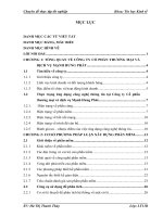
1.2 Components of a CNC Machining System
The main components of a CNC system are shown in Figure 1-1. These are:
1. A Computer Aided Design/Computer Aided Manufacturing (CAD/CAM) program. The part
designer uses the CAD/CAM program to generate an output file called a part program. The
part program, often written in “GCode,” describes the machine steps required to make the
desired part. You can also create a GCode program manually.
2. A file transfer medium such as a USB flash drive, floppy disk, or network link, transfers the
output of the CAD/CAM program to a Machine Controller.
3. A Machine Controller. The Machine Controller reads and interprets the part program to con-
trol the tool which will cut the workpiece. Mach3, running on a PC, performs the Machine
Controller function and send signals to the Drives.
1-3
4. The Drives. The signals from the Machine Controller are amplified by the Drives so they are
powerful enough and suitably timed to operate the motors driving the machine tool axes.
5. The machine tool. The axes of the machine are moved by screws, racks or belts which are
powered by servo motors or stepper motors.
Figure 1-1: Main Parts of a CNC System
Although a milling machine is illustrated, the machine could be a router or a plasma or laser cutter.
If the interfaces exist, in addition to controlling tool position the Machine Controller can start and stop
the spindle motor, control its speed, turn coolant on and off, and check that a part program’s commands
or the Operator are not trying to move any machine axis beyond its limits.
The Machine Controller can also have controls such as pushbuttons, a keyboard, potentiometer knobs,
a manual pulse generator (MPG) wheel, or a joystick so that the Operator can control the machine
manually and start and stop the running of the part program. The Machine Controller has a display so
that the Operator knows what is happening.
Because the commands of a GCode program can request complicated coordinated movements of the
machine axes, the Machine Controller has to be able to perform a lot of calculations in “real-time” (e.g.
cutting a helix requires a lot of trigonometric calculation). Historically this made it an expensive piece
of equipment.
1-4
1.3 How Mach3 Fits In
Mach3 is a software package that runs on a PC and turns it into a very powerful and economical
Machine Controller to replace (3) in Figure 1-1.
To run Mach3, you need a PC running the Windows 2000, Windows XP, or Windows 32-bit Vista
operating system. (Windows Vista may require a registry patch, available at
www.machsup-
port.com.) ArtSoft USA recommends at least a 1GHz processor with a 1024 x 768 pixel resolution
screen. A desktop machine will give much better performance than most laptops and be considerably
cheaper. You can use this computer for any other functions in the workshop (such as (1) in Figure 1-1 -
running a CAD/CAM package) when it is not controlling your machine.
Mach3 and its parallel port driver communicate with the machine hardware through one (or optionally
two) parallel (printer) ports. If your computer does not have a parallel port (more and more computers
are being built without one), you can buy a motion controller board from a third-party vendor that uses
a USB port or Ethernet for communication. Use of a motion controller board can remove considerable
processing load from the computer, so you may want to consider using one to get the performance
advantage even if your computer does have a parallel port available. Mach3 generates step pulses and
direction signals to perform the steps defined by a GCode part program and sends them to the port(s)
or motion controller board.
The drivers for your machine's axis motors must accept March3’s step pulses and direction signals.
Virtually all stepper motor drivers work like this, as do modern DC and AC servo systems with digital
encoders. Beware if you are converting an old NC machine whose servos may use resolvers to mea-
sure position of the axes as you will have to provide a complete new drive for each axis.
To set up a CNC system to use Mach3, you must install the Mach3 software on your computer, and
properly connect your motor drives to the computer’s ports. These operations are described in the fol-
lowing chapters.
1.4 What Mach3 Can Do
Mach3 is a very flexible program designed to control machines such as milling machines, lathes,
plasma cutters, and routers. Features of these machines that are used by Mach3 include:
• Some user controls. An emergency stop (EStop) button must be provided on every machine.
• Two or three axes of motion, which are usually at right angles to each other (referred to as X, Y,
and Z).
• A tool which moves relative to a workpiece. The origin of the reference axes is fixed in relation to
the workpiece. The relative movement can be by (1) the tool moving (e.g. the quill of a milling
spindle moves the tool in the Z direction, or a lathe tool mounted on a cross-slide and a saddle
moves the tool in the X and Z directions) or by (2) the table and workpiece moving (e.g. on a knee
type mill the table moves in the X, Y, and Z directions while the tool remains fixed in the spindle).
And optionally:
• Some switches to say when the tool is in the “Home” position.
• Some switches to define the limits of permitted relative movement of the tool.
• A controlled “spindle.” The spindle can rotate the tool (mill) or the workpiece (turning).
• Up to three additional axes. These can be either Rotary (i.e. their movement is measured in
degrees) or Linear. One of the additional linear axes can be slaved to the X or Y or Z axis. The two
1-5
will move together at all times in response to a part program's moves and to your jogging, but they
will each be referenced separately. (see Section 5.6.4 for more details).
• A switch or switches which interlock the guards on the machine.
• Controls for the way coolant is delivered (Flood and/or Mist).
• A probe in the tool holder that allows digitizing of an existing part.
• Encoders, such as linear glass scales, which can display the position of parts of the machine.
• Special functions.
Most connections between your machine and the PC running Mach3 are made through the parallel
(printer) port(s) of the computer. A simple machine will need only one port; a complex one will need
two.
Connections for control of special functions like an LCD display, a tool-changer, axis clamps, or a
swarf conveyor can also be made through a ModBus device (e.g. a PLC or Homann Designs ModIO
controller).
Buttons can be interfaced by a “keyboard emulator” which generates pseudo-key presses in response
to input signals.
Mach3 will control up to six axes simultaneously, coordinating their movement with linear interpola-
tion or perform circular interpolation on two axes (out of X, Y or Z) while simultaneously linearly
interpolating the other four with the angle being swept by the circular interpolation. The tool can thus
move in a tapering helical path if required! The feed rate during these moves is maintained at the value
requested by your part program, subject to limitations of the acceleration and maximum speed of the
axes. You can move the axes by hand with various jogging controls.
If the mechanism of your machine is like a robot arm or a hexapod, then Mach3 will not be able to
control it because of the kinematic calculations that would be needed to relate the “tool” position in X,
Y and Z coordinates to the length and rotation of the machine arms.
Mach3 can switch the spindle on, rotating in either direction, and switch it off. It can also control the
rate at which it rotates (rpm) and monitor its angular position for operations like cutting threads.
Mach3 can turn the two types of coolant on and off.
Mach3 will monitor the EStop switch and can take note of the operation of the reference switches, the
guard interlock, and the limit switches
Mach3 can store the properties of up to 256 different tools. If, however, your machine has an automatic
tool changer or magazine, you will have to control it yourself. Mach3 provides program macro capa-
bility, but you must do the programming.
1-6
This is a blank left-hand page for two-sided printing.
2-1
Chapter 2 Installing the Mach3 Software
If you haven’t done so already, download the Mach3 software from www.machsupport.com and try it
out on your computer. You do not need a machine tool to be connected. Indeed, for the present it is
better not to have one.
If you have bought a complete CNC system from a reseller, then some or all of the installation steps
described in this chapter may have already been done for you.
2.1 Installation
Mach3 is distributed by ArtSoft USA over the Internet. You download the package as one self install-
ing file (which, in the present release, is about 25 megabytes). When installed, it will run for an unlim-
ited period as a demonstration version. As demonstration software, it places a few limitations on the
speed, the size of job that can be undertaken, and the specialist features supported. When you purchase
a licence, you can “unlock” the demonstration version you have already installed and configured to
give full software functionality. Details of pricing and options are available at www.machsupport.com
.
2.1.1 Downloading
Download the installation package from www.machsupport.com. Use the right mouse button and Save
Target as… to put the self-installing file on the Desktop or in a convenient folder. You should be
logged in to Windows as an Administrator.
When the file has downloaded, it can be run immediately by using the Open button on the download
dialog window, or the download dialog window can be closed and the installation done later. When
you want to do the installation, run the file you downloaded and saved. For example, if you saved the
installation file on the Desktop, just double-click it. If you saved the file in a folder, run Windows
Explorer (right click Start button), and double-click on the name of the downloaded file in the folder.
2.1.2 Installing
This section will guide you through the installation of the Mach3 software. If you already have a ver-
sion of Mach3 installed on the computer, you can install the new version on top of it. You do not need
to remove the old version first.
2.1.2.1 If a machine tool is connected, disconnect it now.
You do not need a machine tool connected to install the software. In fact, if you are just starting it is
probably better not to have one connected. If a machine tool is connected to your computer, note where
the cable or cables from the machine tool are plugged into your PC. Turn off the PC, the machine tool,
2-2
and its drives, and unplug the 25 pin connector(s) from the back of the PC. Now switch the PC back
on.
2.1.2.2 Run the Mach3 software installation package.
When you run the downloaded file, you will be guided through the usual installation steps for a Win-
dows program such as accepting the license conditions and selecting the folder for Mach3. ArtSoft
USA recommends that you allow Mach3 to use its default installation folder
C:\Mach3.
The background image during installation is the standard Mach3Mill screen – do not worry if you are
planning to control a lathe, as Mach3Turn is also being installed.
You will be asked if you want to install various program components, as shown in Figure 2-1:
Figure 2-1: Select Program Components Screen
You will need the parallel port driver if you are using the computer’s parallel port(s) to interface with
the machine tool. If you are using a motion controller board from a third-party vendor that uses USB or
Ethernet, you should uncheck the parallel port driver.
The Wizards are a set of macros that let you quickly create GCode to do common tasks such a bolt cir-
cles, pockets, etc. You will almost certainly find these useful. Installing the Wizards also installs the
Mach3 Addons for Mill, although they require a separate license for activation.
The XMLs are the files that hold Mach3’s configuration information. There are three default
.XML
files:
Mach3Mill.xml, Mach3Turn.xml, and Mach3Plasma.xml. These give you a known starting
point for creating your own custom profiles. ArtSoft USA STRONGLY recommends you create cus-
tom profiles of your own instead of modifying the default profile(s). If you have previously modified
one or more of the default profiles, however, and do not want to overwrite your configuration informa-
tion, you should uncheck the XMLs box.
2-3
LazyCam is a beta-release free importer included with Mach3. Its purpose is to import standard dxf,
cmx, and other file types to allow those that do not use CAM programs to more easily generate GCode
to be run under Mach3. You do not need it to run the Mach3 software.
The Screen Sets define Mach3’s screen appearance. Unless you have created your own custom
screens, you will want these.
When you have selected the components you want, click the Next button.
The installation procedure will ask if you want to create a custom profile, as shown in Figure 2-2:
Figure 2-2: Create a Custom Profile Screen
As previously described, ArtSoft USA strongly recommends that you create custom profiles instead of
modifying the default profiles. This screen lets you clone one or more of the default profiles, assigning
your own names to the cloned profiles. For example, if you click the Mill Profile button, the screen
shown in Figure 2-3 appears.
Figure 2-3: Create Mill Profile
Enter the name you want to assign to the profile (possibly “MyMill”) and click the OK button. If you
want, you can create several different profiles. When you have created your custom profile(s), click the
Next button.
2-4
2.1.2.3 If You’re Using Windows Vista
Vista may require a registry patch for the Mach3 parallel port driver to run. (If you are using a third-
party motion controller board that communicates with USB or Ethernet instead of the parallel port
driver, you do not need the patch.) First, do the normal Mach3 installation, then install the patch. The
patch is available at w
ww.machsupport.com, together with any updated information about using Win-
dows Vista. Download the patch as a Zip file, save it, and unzip it to extract the file
memoryover-
ride.reg
. Double-click the filename to run it. memoryoverride.reg modifies the registry to allow
Mach3’s driver to run.
Now, go to the
C:\Mach3 folder, (or wherever you installed Mach3). Right click drivertest.exe
and select “Run as Administrator.” It should tell you to reboot. Do so, or your computer will crash. No
question about it.
Now you should be able to run Mach3. Try
drivertest.exe again, and it should run.
Note: You may get errors reported when running DriverTest. In fact it may not run at all the first time,
then Vista will ask you if you want to run it in compatibility mode. DO so, and it will run.
2.1.3 The Vital Reboot
You must reboot Windows before running Mach3. This reboot is vital. If you do not do it, you will get
into great difficulties which can only be overcome by using the Windows Control Panel to uninstall the
driver manually. So please reboot now.
If you are interested in knowing why the reboot is required, then read on. If not, you can skip to Sec-
tion 2.2.
Although Mach3 will appear to be a single program when you are using it, it actually consists of two
parts: a driver, which is installed as part of Windows like a printer or network driver, and a graphical
user interface (GUI).
The driver is the most important and ingenious part. Mach3 must be able to send very accurately timed
signals to control the axes of the machine tool. Windows likes to be in charge. It runs normal user pro-
grams when it has nothing better to do itself. Because Mach3’s operation is so time-critical, it cannot
be a “normal user program.” It must be at the lowest level inside Windows (that is, it handles inter-
rupts). Furthermore, to do this at the high speeds possibly required (each axis may be given attention
up to 100,000 times per second), the driver needs to tune its own code. Windows does not approve of
this (it's a trick that viruses play), so it has to be asked to give special permission. This process requires
the reboot. So if you have not done the re-boot, then Windows will give the Blue Screen of Death and
the driver will be corrupt. The only way out of this is to manually remove the driver.
Having given these dire warnings, it is only fair to say that the reboot is required only when the driver
is first installed. If you update your system with a newer version, then the reboot is not vital. The
install sequence does, however, still ask you to do it. Windows XP boots reasonably quickly, so it is
not much hardship to do it every time.
2.2 Testing The Installation
So you have rebooted! (If you haven’t, go back and read Section 2.1.3.)
ArtSoft USA recommends you now test the installed system. As mentioned above, Mach3 is not a sim-
ple program. It takes great liberties with Windows to perform its job; this means it will not work on all
systems due to many factors. For example, the QuickTime system monitor (
qtask.exe) running in
2-5
the background can kill Mach3, and there may be other programs you are not even aware of on your
system that can do the same. Windows can and does start many processes in the background. Some
appear as icons in the system tray (bottom right of screen), while others do not show themselves in any
way. Other possible causes of erratic operation are local area network connections which may be con-
figured to automatically speed detect. You should configure these to the actual speed (10 Mbps or 100
Mbps) of your network. Finally, a machine that has been surfing the Internet may have gained one or
more of a host of “robot” type programs which spy on what you are doing and send data over the 'net to
their originators. This traffic can interfere with Mach3 and is not something you want anyway. Use a
spyware scanner such as Spybot, available from www.safer-networking.org
, to locate and delete unde-
sirable software on your machine.
Because of these factors, it is important, though not mandatory, that you test your system when you
suspect something is wrong or you just want to check that an install went well.
2.2.1 If You Are Using the Default Parallel Port Driver
If you are using a third-party motion controller in place of the parallel port driver, you can skip this
section.
If you are using the Mach3 parallel port driver, it is worthwhile to set up an icon for a desktop shortcut
to another Mach3 program. Use Windows Explorer (right-click Start), navigate to the folder in which
you placed the Mach3 installation, and create a shortcut to
DriverTest.exe by right-clicking on the
DriverTest.exe filename. Drag this shortcut onto your desktop. DriverTest.exe tests the opera-
tion of the parallel port driver.
Double click the DriverTest icon that you just set up, or run the program
DriverTest.exe from the
Mach3 installation folder. Running
DriverTest.exe will install the parallel port driver if it was not
installed previously. A screen shot of DriverTest is shown in Figure 2-4.
2-6
Figure 2-4: The Running DriverTest Program
You can ignore all the boxes with the exception of the Pulses Per Second. It should be fairly steady
around your chosen kernel pulse frequency (25,000 Hz, 35,000 Hz, etc.). Your pulse rate may vary,
however, even quite wildly. This is because Mach3 uses the Windows clock to calibrate its pulse timer
and, over a short time scale, the Windows clock can be affected by other processes loading the com-
puter. So you may actually be using an “unreliable” clock (the Windows one) to check Mach3 and so
get the false impression that Mach3's timer is unsteady.
DriverTest evaluates the pulse stream and displays a Pulse Rating below the Timer Variations graph.
In Figure 2-4, the pulse rating is Excellent. If your system has more variation, the pulse rating may be
good, fair, or poor. If you see a screen similar to Figure 2-4, with only small spikes on the Timer Vari-
ations graph, a steady number of pulses per second, and a good or excellent rating, everything is work-
ing well. Close the DriverTest program and proceed to Section 2.3 describing Mach3 Profiles, below.
If you have problems with the installation, refer to Section 2.4, Installation Problems.
2-7
2.3 Mach3 Profiles
Profile files (.XML files, stored in the \Mach3 installation folder) define the operating appearance and
characteristics of Mach3, allowing Mach3 to be configured for use with different types of machines:
lathes, milling machines, plasma cutters, routers, etc. All your configuration setup choices are saved in
the profile file that you select.
The installation wizard creates desktop icons for Mach3Mill, Mach3Turn, Plasma, and Mach3 Loader.
Mach3Mill, Mach3Turn, and Plasma are shortcuts that run Mach3 with a preconfigured profile for a
particular type of machine. The profile to use is identified by a “
/p” argument in the shortcut target.
(To see this command line, right-click on one of the desktop shortcuts and select Properties from the
pop-up menu. See also Figure 2-7.)
While you can use one these shortcuts to start a preconfigured system, ArtSoft USA recommends
that you do not. Instead, you should create your own profile(s). Doing so has two important benefits:
• The supplied profiles (
Mach3Mill.XML, Mach3Turn.XML, and Plasma.XML) will not be modi-
fied by your configuration setup. They will always be a known starting point for creating addi-
tional profiles, and a recovery point if your own profile(s) becomes corrupted.
• Your profile(s) will not be overwritten and lost if you install an updated version of Mach3. During
an update, the default profiles (
Mach3Mill.XML, etc.) will be overwritten with a new version. If
the old version of
Mach3Mill.XML contained all your laboriously-entered configuration informa-
tion, you will not be happy!
The Mach3 Loader shortcut has no preset profile choice. It runs Mach3 with a startup menu asking you
to choose which profile to use. It also provides a way for you to create your own custom profiles.
2.3.1 Creating a Profile
Run Mach3Loader using the preconfigured shortcut. The window shown in Figure 2-5 will appear.
Figure 2-5: Profile Selection Window
Click the Create Profile button. The window shown in Figure 2-6 will appear.
2-8
Figure 2-6: Create Profile Window
In the left-hand list, click on the profile you want to clone (in this example, it is Mach3Mill). Type the
name you want to assign to the new profile in the New Profile Name box. Do not check the Default
Profile Values box. (Selecting Default Profile Values produces a minimal profile.)
Click the OK button.
You can run Mach3 with your new profile by running Mach3Loader, selecting your profile name in the
list, and clicking the OK button. For convenience, you may want to create a shortcut to Mach3 with
your profile name in the command line, as shown in Figure 2-7.
Figure 2-7: Shortcut to “MyMill”
2-9
2.4 Installation Problems
Two things may occur when running the test that indicate a problem:
1. The display reads “Driver not found or installed, contact Art.” This display will appear if the driver
did not install into Windows. This can occur on XP systems that have a corruption of their driver
database. The fix is to reinstall Windows. Or, you may be running Win2000. Win2000 has a bug/
feature that can interfere with loading the driver. The driver may need to be loaded manually. See
Section 2.4.2.
2. If the display reads “Taking over…3…2…1 ” but then reboots, one of two things has occurred.
Either you didn’t reboot when asked during the installation of Mach3 (Told you! See Section
2.1.3), or the driver is corrupted or unable to be used in your system. In this case, follow the
instruction in Section 2.4.2 and remove the driver manually, then re-install Mach3. If the same
thing happens, please notify ArtSoft USA using the e-mail link on www.machsupport.com
and
you will be given guidance.
A few systems have motherboards that have hardware for the APIC timer but whose BIOS code does
not use it. This will confuse the Mach3 install. A batch file
SpecialDriver.bat is available in the
Mach3 installation folder. Find it with Windows Explorer and double-click it to run it. This will make
the Mach3 driver use the older i8529 interrupt controller. You will need to repeat this process when-
ever you download an upgraded version of Mach3 as installing the new version will replace the special
driver. The file
OriginalDriver.bat reverses this change.
Windows “experts” might be interested to see a few other things. The white rectangular window is a
type of timing analyzer. When it is running it displays a line with small variations indicated. These
variations are the changes in timing from one interrupt cycle to another. There should be no lines
longer than ¼ inch or so on an 17" screen on most systems. Even if there are variations its possible
they are below the threshold necessary to create timing jitters so when your machine tool is connected
you should perform a movement test to see if jogging and G0/G1 moves are smooth.
2.4.1 Running DriverTest After a Mach3 Crash
Should you for any reason have a situation when running Mach3 where it crashes - this might be an
intermittent hardware problem or a software bug – then you must run DriverTest.exe as soon as possi-
ble after Mach3 has failed. If you delay for two minutes then the Mach3 driver will cause Windows to
fail with the usual “Blue Screen of Death.” Running DriverTest resets the driver to a stable condition
even if Mach3 disappears unexpectedly.
You may find, after a crash, that it fails to find the driver the first time it is run. In this case merely run
it again as the first run should fix things up.
2.4.2 Manual Driver Installation and Uninstallation
You need to read and do this section only if you have not successfully run the DriverTest pro-
gram.
The driver (
Mach3.sys) can be installed and uninstalled manually using the Windows Control Panel.
The dialog boxes differ slightly between Windows 2000 and Windows XP, but the steps are identical.
1. Open the Windows Control Panel and double-click on the icon or line for System.
2. Select Hardware and click Add Hardware wizard. Windows will look for any new actual hard-
ware (and find none).
3. Tell the wizard you have already installed it and then proceed to the next screen.
2-10
4. You will be shown a list of hardware. Scroll to the bottom of this and select Add a new hardware
device and move to the next screen.
5. On the next screen you do not want Windows to search for the driver so select Install the hardware
that I manually select from a list (Advanced)
6. The list you are shown will include an entry for Mach1/2 pulsing engine. Select this and go to the
next screen.
7. Click Have disc and on the next screen point the file selector to your Mach3 folder (
C:\Mach3 by
default). Windows should find the file Mach3.inf. Select this file and click Open. Windows will
install the driver.
The driver can be uninstalled rather more simply.
1. Open the Control panel and double-click on the icon or line for System.
2. Select Hardware and click Device Manager
3. You will be shown a list of devices and their drivers. Mach1 Pulsing Engine has the driver Mach3
Driver under it. Click on the
+ symbol to expand the tree if necessary. Right-click on Mach3
Driver. This will display a short menu that includes the option to uninstall it. Click Uninstall. This
will remove the file
Mach3.sys from the Windows folder. The copy in the Mach3 folder will still
be there.
There is one final point to note. Windows remembers all the information about the way you have con-
figured Mach3 in a Profile file. This information is not deleted by un-installing the driver and deleting
other Mach3 files, so it will remain whenever you upgrade the system. However in the very unlikely
event that you need a totally clean installation from scratch then you may need to delete the
.XML pro-
file file or files.
3-1
Chapter 3 Introducing the Mach3 Screens
and Commands
You are now ready to try a “dry run” of Mach3. It will be easier to understand how to set up your actual
machine tool after you have experimented a bit with the software. You can “pretend” to machine and
learn a lot even if you do not have a CNC machine tool yet. If you do have one, then make sure it is not
yet connected to the PC.
Mach3 is designed so that it is very easy to customize its screens to suit the way you work. This means
that the screens you see may not look exactly like those in this manual if you bought a preconfigured
system from a vendor. If there are major differences, then your system supplier should have given you
a revised set of screenshots to match your system.
3.1 Screens
If you created your own custom profile as shown in Figure 2-2 and Figure 2-3, Mach3 will have cre-
ated a shortcut icon on the desktop with the name of your custom profile. Double-click the appropriate
icon to launch the program using that profile. You can also double-click the Mach3 Loader icon to run
the program, select from a list the name of the profile to use, then click the OK button. (You did create
your own profile as described in Section 2.3, didn’t you? If not, go back and read that section.)
If you have installed more than one driver or third-party motion control plugin, you may see a screen
similar to Figure 3-1. (The content of the screen you see will depend on what you have installed.)
Select what you want to use by clicking the appropriate button, then click the OK button.
Figure 3-1: Select Control Device Screen