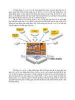
vi điều khiển và ứng dụng
Bạn đang xem bản rút gọn của tài liệu. Xem và tải ngay bản đầy đủ của tài liệu tại đây (1.13 MB, 18 trang )
1
Serial Communication
Chuyên đề II
Vi điều khiển và ứng dụng
Truyền thông nối tiếp
2 the Universal Asynchronous Receiver and
Transmitters (UARTs)
2 the SPI synchronous serial interfaces
2 the I2 C synchronous serial interfaces
2
2
Synchronous serial
3
Asynchronous Serial
Interfaces
4
3
Some comparisons
5
More
6
4
Synchronous Communication
Using the SPI Modules
7
8
5
Giải thích các bit điều khiển
9
Bít điều khiển
10
6
SPI overview
Truyền nhận dữ liệu 16 bit hoặc 8bit
Full-duplex, synchronous communication
Truyền 3 dây
Hỗ rợ 4 định dạng truyền khác nhau và tốc độ
cao nhất là 10Mbit/s
Buffered Transmission and Reception
11
SPI - Master / Slave
SPI module có thể là Master hoặc Slave
Chỉ có 1 Master và 1 Slave thực hiện thao tác
Master khởi tạo bằng chọn bit MSTEN,
SPIxCON<5>
Master tạo ra xung tại chân SCK
Tần số xung quyết định bởi 2 giá trị Prescaler
bits (PPRE) và Secondary Prescaler (SPRE) bits
in SPIxCON register
Fsck = Fcy / (PPRE * SPRE)
12
7
13
SPI – Định dạng dữ liệu truyền
4 clock formats - set by CKP and CKE bits
in the SPIxCON register
SCK is low when module is idle, SDO changes on
clock going high (CKP=0, CKE=0)
SCK is low when module is idle, SDO changes on
clock going low (CKP=0, CKE=1)
SCK is high when module is idle, SDO changes on
clock going low (CKP=1, CKE=0)
SCK is high when module is idle, SDO changes on
clock going high (CKP=1, CKE=1)
14
8
Ví dụ
15
SPI - Transmission
Dữ liệu được truyền bởi set bit SPIEN bit trong thanh ghi SPIxSTAT
SPIxBUF là thanh ghi nhận dữ liệu
You can write SPIxBUF while data is being shifted out through
SPIxSR
SPITBF bit thông báo bộ đệm đầy
Wait until SPITBF = 0 to write data
Transmission of the new data starts as soon as SPIxSR is idle
16
9
SPI - Reception
Việc truyền và nhận diễn ra đồng thời
When all bits of data have been shifted in through SPIxSR,
SPIxSR contents are transferred to Receive Buffer
SPI interrupt (indicated by SPIIF bit and enabled by SPIIE bit)
is generated so that buffer can be read
SPIxBUF subject to Receive Overflow
SPIRBF bit in the SPIxSTAT register = 1 indicates that the
Receive Buffer is full
SPIxBUF must be read before new data is completely shifted in
17
Configuration
18
10
SPI – Định dạng dữ liệu
Dữ liệu có thể là 8 bit hoặc 16bit
Đối với SPI
For 8-bit data, Master generates 8 SCK pulses
For 16-bit data, Master generates 16 SCK pulses
Chế độ 16 bít xác lập bởi bit MODE16 bit in the
SPIxCON register
19
SPI - Framed SPI
SPI supports Frame Synchronization
Enabled by setting FRMEN bit in the SPIxCON
register
SCK pulses are continuous in this mode
20
11
SPI - Framed SPI
Frame Master generates Frame Sync pulses
Frame Master or Slave mode is selected by clearing
or setting the SPIFSD bit in the SPIxCON register
Shifting of data starts only after a Frame Sync
pulse is generated on the SS pin
4 possible Framed SPI modes
SPI Master, Frame Master
SPI Master, Frame Slave
SPI Slave, Frame Master
SPI Slave, Frame Slave
21
SPI - chức năng phụ
Slave Select (SS) pin functionality
In this mode, the Slave functions only as long as
the SS pin is driven low
Enabled by setting SSEN bit in the SPIxCON
register
Slave Wake-up from SLEEP
Since SCK pulses are provided by the Master, SPI
Slave can function in SLEEP
Slave Reception wakes up the device from
SLEEP
22
12
Ví dụ ghép nối với Serial EEROM
25L256
// 1. init the SPI peripheral
#define SPI_CONF 0 x 8120 // SPI on, 8-bit master, CKE=1,CKP=0
TCSEE = 0; // make SSEE pin output
CSEE = 1; // de-select the EEPROM
SPI2CON = SPI_CONF; // select mode and enable
// send one byte of data and receive one back at the same time
int writeSPI2( int i)
{
SPI2BUF = i; // write to buffer for TX
while( !SPI2STATbits.SPIRBF); // wait for transfer complete
return SPI2BUF; // read the received value
}//writeSPI2
23
Đọc Serial ROM
// 25LC256 Serial EEPROM commands
#define SEE_WRSR 1 // write status register
#define SEE_WRITE 2 // write command
#define SEE_READ 3 // read command
#define SEE_WDI 4 // write disable
#define SEE_STAT 5 // read status register
#define SEE_WEN 6 // write enable
24
13
Ví dụ chương trình đầy đủ
25
Writing/read Data to the
EEPROM
// send a Write command
CSEE = 0; // select the Serial EEPROM
writeSPI2( SEE_WRITE); // send command, ignore data
writeSPI2( ADDR_MSB); // send MSB of memory address
writeSPI2( ADDR_LSB); // send LSB of memory address
writeSPI2( data); // send the actual data
// send more data here to perform a page write
CSEE = 1; // start actual EEPROM write cycle
// send a Write command
CSEE = 0; // select the Serial EEPROM
writeSPI2( SEE_READ); // send command, ignore data
writeSPI2( ADDR_MSB); // send MSB of memory address
writeSPI2( ADDR_LSB); // send LSB of memory address
data=writeSPI2( 0); // send dummy, read data
// read more data here sequentially incrementing the address
CSEE = 1; // terminate the read sequence
26
14
Read 32bit values
27
Write 32bit values
28
15
DAC ví dụ MCP4921
29
Ví dụ chân tín hiệu
CH0 : Analog Input Channel 0
CH1 : Analog Input Channel 1
CH2 : Analog Input Channel 2
CH3 : Analog Input Channel 3
DGND : Digital Ground.
CS: Chip Select.
Din : Connected to AVRs MOSI
Dout : Connected to AVRs MISO
CLK : Connected to AVRs SCK
Agnd : Analog Ground
Vref : Reference Voltage.
Vdd : Positive supply (5v).
30
16
SPI transaction
31
Example codes
32
17
ADC 12 bit, MCP 3204
33
SPI Transaction
34
18
Ping pong code
35