MOVABLE SCAFFOLDING SYSTEM MSS Moving Scaffolding SystemSpan length 15 80 m Usual Total Length 500 m several kms Usual cycle time span 6 10 days
Bạn đang xem bản rút gọn của tài liệu. Xem và tải ngay bản đầy đủ của tài liệu tại đây (1.23 MB, 23 trang )
1
MOVABLE SCAFFOLDING SYSTEM
MSS - Moving Scaffolding System
Span length 15 - 80 m
Usual Total Length 500m – several km’s
Usual cycle time / span 6 – 10 days
2
Our strong technical support team can offer services at various levels:
The Movable Scaffolding System - MSS:
Complete or partial delivery
•
design, know-how & construction engineering
•
steel structure
•
hydraulic equipment
•
launching equipment
•
special equipment
Consultancy & supervision
•
experienced supervision and consultation during fabrication,
assembly & operation
•
design, know-how & construction engineering
•
Feasibility studies
3
MSS - Moving Scaffolding System
The MSS was first designed in close co-operation with Norwegian
contractors in the 1970's.
The system has since then been developed and successfully used in various
major bridge projects in Scandinavia and world wide.
The design of our advanced equipment has been improved and optimized
over the years, based on our wealth of experience from over 100 projects.
The system is light weight, easy to assemble, practical in design,
supported by internationally known hydraulic and cranage systems, and
most importantly, efficient in operation.
Strukturas supplies two types of MSS:
•
Overhead MSS
•
Underslung MSS
4
Overhead MSS
5
The development of our cost-effective system over the years, stems from the
need to reduce the high costs of construction manpower in Norway. Today,
our MSS for cast-in-situ bridges can offer many cost-saving advantages to
your bridge construction projects, through:
Overhead MSS for the construction of
Cast in-Situ Bridges
•
optimized design
•
ease of assembly
•
efficient operation
A quick, reliable and economical solution for modern bridge construction
6
Overhead MSS
The MSS can also easily be adapted to any bridge cross section
(single box, double box, double T, etc.) and span configuration.
This flexibility provides the contractor the opportunity to re-use the
equipment from one project to another.
7
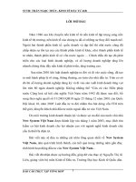
Overhead MSS - Components
FRONT & REAR
NOSES
MAIN
GIRDER
TRANSVERSE
TRUSS
LAUNCHING
WAGON
PIER
SUPPORT
FORMWORK
TENSION
BARS
8
Overhead MSS -
A typical construction cycle
After concreting, curing and tensioning of
cables, the Main Girder and the Transverse
Trusses are lowered by the main jacks at
the rear and front Pier Supports.
9
After concreting, curing and tensioning of
cables, the Main Girder and the Transverse
Trusses are lowered by the main jacks at
the rear and front Pier Supports.
The Main Girder is now resting on the
launching wagon. The Formwork is
disconnected from the Tension Bars.
Overhead MSS -
A typical construction cycle
10
After concreting, curing and tensioning of
cables, the Main Girder and the Transverse
Trusses are lowered by the main jacks at
the rear and front Pier Supports.
The Main Girder is now resting on the
launching wagon. The Formwork is
disconnected from the Tension Bars.
The Formwork is now lowered and the
MSS is in the launching position.
Overhead MSS -
A typical construction cycle
11
After concreting, curing and tensioning of
cables, the Main Girder and the Transverse
Trusses are lowered by the main jacks at
the rear and front Pier Supports.
The Main Girder is now resting on the
launching wagon. The Formwork is
disconnected from the Tension Bars.
The Formwork is now lowered and the
MSS is in the launching position.
Overhead MSS -
A typical construction cycle
12
After concreting, curing and tensioning of
cables, the Main Girder and the Transverse
Trusses are lowered by the main jacks at
the rear and front Pier Supports.
The Main Girder is now resting on the
launching wagon. The Formwork is
disconnected from the Tension Bars.
The Formwork is now lowered and the
MSS is in the launching position.
Overhead MSS -
A typical construction cycle
13
The MSS is ready for launching. The
launching operation to the next concreting
position is to be carried out.
NOTE
The first span is usually 0,8 x max. span. The following
pours will cantilever by 1/5 of the span lengths.
“0,8 x L” “L” “L”
Overhead MSS -
A typical construction cycle
14
The MSS is ready for launching. The
launching operation to the next concreting
position is to be carried out.
Overhead MSS -
A typical construction cycle
15
Overhead MSS -
A typical construction cycle
16
and the MSS is now ready to be raised into
the concreting position.
In the next position, the Formwork is
assembled and rigged into place.
A Rear Support is rigged in place, and will
provide the lifting of the Main Girder by
means of the two rear hydraulic main
jacks.
The Suspension Bars are adjusted,
However, no Pier Support will be available
at the rear end of the Main Girder this time.
“0,2 x L”
“0,2 x L”
Overhead MSS -
A typical construction cycle
17
The MSS is now ready to be lifted into the
concreting position.
Overhead MSS -
A typical construction cycle
18
The MSS is now ready to be lifted into the
concreting position.
Overhead MSS -
A typical construction cycle
19
Overhead MSS -
Rio Major, Portugal
20
Overhead MSS -
Rio Major, Portugal
21
Overhead MSS -
Grandola, Portugal
22
Overhead MSS – Bid 374, Taiwan, R.O.C.
23
Overhead MSS – Bid 374, Taiwan, R.O.C.