Bài giảng Thiết kế logic số (VLSI design): Chương 4.3 - Trịnh Quang Kiên
Bạn đang xem bản rút gọn của tài liệu. Xem và tải ngay bản đầy đủ của tài liệu tại đây (1.04 MB, 22 trang )
Thiết kế logic số
(VLSI design)
Bộ môn KT Xung, số, VXL
06/2010
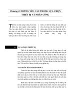
Quy trình thiết kế trên FPGA
ISE (Intergrated Software Enviroment)
Quy trình thiết kế trên FPGA
Design and implement a simple unit permitting to
speed up encryption with RC5-similar cipher with
fixed key set on 8031 microcontroller. Unlike in
the experiment 5, this time your unit has to be able
to perform an encryption algorithm by itself,
executing 32 rounds…..
Specification (Lab Experiments)
VHDL description (Your Source Files)
Library IEEE;
use ieee.std_logic_1164.all;
use ieee.std_logic_unsigned.all;
entity RC5_core is
port(
clock, reset, encr_decr: in std_logic;
data_input: in std_logic_vector(31 downto 0);
data_output: out std_logic_vector(31 downto 0);
out_full: in std_logic;
key_input: in std_logic_vector(31 downto 0);
key_read: out std_logic;
);
end AES_core;
Synthesis
Functional simulation
Post-synthesis simulation
Quy trình thiết kế trên FPGA
Implementation
Timing simulation
Configuration
On chip testing
VHDL and Schematic
library IEEE;
use IEEE.STD_LOGIC_1164.ALL;
entity compare_module is
Port (value : in std_logic_vector (3 downto 0);
res : out std_logic);
end compare_module;
architecture Behavioral of compare_module is
signal std : std_logic_vector (4 downto 0);
begin
val <= '0' & value;
process (val, std)
begin
sub <= val - std;
res <= sub(4);
end process;
end Behavioral;
Technology independent,
HDL
Easy to handle complex design
Easy for Testing
Synthesis
Synthesis
Check syntax
& synthesis
Generate
nelist (post
simulation
model)
(optional)
Create Technology
schematic (optional)
Create RTL
schematic
(optional)
Synthesis
UNISIM Library
library IEEE;
use IEEE.STD_LOGIC_1164.ALL;
entity compare_module is
Port (value : in std_logic_vector (3 downto 0);
res : out std_logic);
end compare_module;
architecture Behavioral of compare_module is
signal std : std_logic_vector (4 downto 0);
begin
val <= '0' & value;
process (val, std)
begin
sub <= val - std;
res <= sub(4);
end process;
end Behavioral;
Synthesis - netlist
library IEEE;
library IEEE;
use IEEE.STD_LOGIC_1164.ALL;
library UNISIM;
use UNISIM.VCOMPONENTS.ALL;
use UNISIM.VPKG.ALL;
entity sp3_led is
port (
LED1 : out STD_LOGIC;
LED2 : out STD_LOGIC;
...
);
end sp3_led;
architecture Structure of sp3_led is
signal SW8_IBUF_31 : STD_LOGIC;
begin
LED81 : LUT2
generic map(
INIT => X"1"
)
port map (
I0 => SW8_IBUF_31,
I1 => SW7_IBUF_29,
O => LED8_OBUF_15
);
...
Synthesis – Technology Schematic
Synthesis – RTL Schematic
Synthesis – UCF file
# IO location defination
NET "HIGH_voltage" LOC = P102;
NET "LOW_voltage" LOC = P100;
NET "voltage[0]" LOC = P160;
NET "voltage[1]" LOC = P161;
NET "voltage[2]" LOC = P162;
NET "voltage[3]" LOC = P163;
# Timing constraint
INST "LOW_voltage" TNM = "OUT_REG";
INST "HIGH_voltage" TNM = "OUT_REG";
NET "voltage[0]" OFFSET = IN 2 ns VALID
"OUT_REG" RISING;
NET "voltage[1]" OFFSET = IN 2 ns VALID
"OUT_REG" RISING;
NET "voltage[2]" OFFSET = IN 2 ns VALID
"OUT_REG" RISING;
NET "voltage[3]" OFFSET = IN 2 ns VALID
"OUT_REG" RISING;
0.5 ns BEFORE "CLK" TIMEGRP
0.5 ns BEFORE "CLK" TIMEGRP
0.5 ns BEFORE "CLK" TIMEGRP
0.5 ns BEFORE "CLK" TIMEGRP
Implementation
Translate
Post-translate simulation model
Post-map simulation model
Mapping
Implementation
Post-map static Timing
Post-place-route static timing
Place & Route
Post-place-route simulation model
Translate
Synthesis
Circuit netlist
Electronic Design
Interchange Format
EDIF
Timing Constraints
Constraint Editor
Native
Constraint
File
NCF
UCF
User Constraint File
Translation
NGD
Native Generic Database file
Mapping
Chương III FPGA
Place & Route
FPGA Verification
Verification
Function
Timing
On-circut
testing
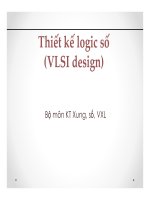
Giao thức truyền tin nối tiếp
IDLE
START
DATA
PARITY
STOP
IDLE
RX
Tbraud
Bit counter
x
0
0
1
2
3
4
5
6
7
8
SAMPLE
ONE BIT
RECEIVING
RX
Sample counter
13
14
15
0
1
2
3
4
5
6
7
8
9
10
11
12
13
14
15
0
1
0
Máy trạng thái khối UART
IDLE
CNT16 = 8 and RX = 1
CNT_BIT = 8
RX = 0, Rx_Reg = 1
START FRAME
DETECTOR
RECEIVE
DATA
CNT16 = 8 and RX = 0
Sơ đồ khối UART
SAMPLE COUNTER
CLK
CLOCK DIVIDER
BIT COUNTER
CLK16
CNT
RESET
ENABLE
CNT
RESET
ENABLE
nRESET
FSM (FINITE STATE MACHINE)
RX_REG
Rx
RX_REG
RECEIVE_REG
DATA REG
LEDs
SHIFT_ENABLE
LOAD
Khối giao tiếp VGA