CDMA and cdma2000 for 3G Mobile Networks_3 pptx
Bạn đang xem bản rút gọn của tài liệu. Xem và tải ngay bản đầy đủ của tài liệu tại đây (420.83 KB, 38 trang )
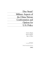
message to the base station that uses this particular pilot (that is,
the target base station). The target base station may then proceed to
join the handoff process and thus exchange necessary messages with
the MSC. The mobile station receives the Direction message at t
3
,
transfers that pilot to the active set, properly updates the candidate
set as well, and sends a Handoff Complete message to the primary
base station.
From instant t
3
, the mobile station continues in the soft handoff
state. At instant t
4
, when the signal level of an active pilot begins to
fall below the pilot drop threshold T_DROP, a timer with a fixed
timeout setting is started. If the signal begins to improve back again
so that it exceeds T_DROP, the timer is stopped and reset, indicating
that this pilot will continue to be active. If, however, the timer
expires at instant t
5
, and if the signal remains below the threshold
for the entire duration from t
4
to t
5
as indicated in the figure, the
mobile station sends a pilot strength measurement message to the
primary base station.
On receiving the message, say, at instant t
6
, the base station sends
a Handoff Direction message to the mobile station. Because the for-
ward traffic channel associated with this pilot is no longer usable,
the base station sends a release request to the MSC, which forwards
Chapter 4
136
T_ADD
t
T_DROP
3
t
1
t
2
t
4
t
5
t
6
t
7
t
Pilot Channel
Signal Strength
Pilot added to candidate set
BTS sends handoff message
Pilot moved to active set
Drop timer started
Timer expires, MS sends measurement data
BTS sends handoff message
Pilot moved to neighbor set
Figure 4-7
Soft handoff in
IS-95
it to the target base station as part of the process to drop it from the
soft handoff.
The mobile station receives the Handoff Direction message at
time t
7
, removes the pilot from the active set, adds it to the neighbor
set, and sends a Handoff Complete message to the base station.
CDMA allows for an idle handoff as well. If a mobile station, while
in the idle state, detects a pilot channel from another base station to
be significantly stronger than the pilot channel of the current base
station, it may decide to initiate a handoff.
cdma2000
System Features
Traffic Types Broadly speaking, cdma2000, like all other 3G tech-
nologies, is expected to support the following types of traffic. The
data rates may vary from 9.6 kb/s to 2 Mb/s:
■ Traditional voice and voice over IP (VoIP)
■ Data services
■
Packet data These services are IP-based with the
Transmission Control Protocol (TCP) or User Datagram
Protocol (UDP) at the transport layer. Included in this category
are the Internet applications, H.323-type multimedia services,
and so on.
■
Circuit-emulated broadband data Examples of this kind of
traffic include fax, asynchronous dial-up access, H.321-based
multimedia services where audio, video, data, and control and
indication are transmitted using circuit emulation over
Asynchronous Transfer Mode (ATM), and so on.
■
SMS
In addition, there are, of course, signaling services.
3G systems are intended for indoor and outdoor environments,
pedestrian or vehicular applications, and fixed environments such as
137
cdmaOne and cdma2000
wireless local loops. Cells sizes may range from a few tens of meters
(say, less than 50 m for picocells) to a few tens of kilometers (in
excess of 35 km for large cells).
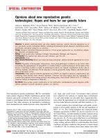
Bandwidth A cdma2000 system may operate at different band-
widths with one or more carriers. In a multicarrier system, adjacent
carriers should be separated by at least 1.25 MHz as shown in Fig-
ure 4-8(a). In an actual multicarrier system, each individual carrier
usually has a bandwidth of 1.25 MHz and is separated from an IS-
95 carrier by means of orthogonal codes. However, when three car-
riers are being used in a multicarrier system, the bandwidth
required is 5 MHz. To provide high-speed data services of the type
discussed previously, a single channel may have a nominal band-
width of 5 MHz as indicated in Figure 4-8(b) with a chip rate of
3.6864 Mc/s (that is, 3 ϫ 1.2288 Mc/s).
5
The bandwidth BW in Fig-
ure 4-8(b), outside of which the power density is negligible, depends
Chapter 4
138
BW
5 MHz
GG
1.25 MHz1.25 MHz
f
(a)
(b)
5 MHz
1
23
Figure 4-8
Bandwidth
requirements in
cdma2000
5
Or, if necessary, the bandwidth of a single channel may be some multiple of 5 MHz.
on the pulse-shaping filter at the baseband.
6
If a raised cosine filter
is used, BW ϭ R
c
(1 ϩ a), where R
c
is the chip rate and a is the roll-
off factor. If a ϭ 0.25, BW ϭ 4.6 MHz, and so the guard band G ϭ
200 kHz. Clearly, an advantage of a wider bandwidth lies in the fact
that it provides more resolvable paths that can be used in a multi-
path diversity receiver to improve the system performance.
Quality of Service (QoS) At any time, multiple applications may
run on a mobile station. A user may request a desired QoS depend-
ing on the application, and the network is expected to guarantee the
requested quality without any (noticeable) degradation in the QoS
contracted by other active users.
Packet Mode Data Services cdma2000 supports packet mode
data services [1]. Starting from an initial state, if there is a packet
to send, the user attempts to establish the dedicated and common
control channels using the multiple-access slotted Aloha scheme.
7
In
139
cdmaOne and cdma2000
6
Recall that the purpose of this filter is to reduce out-of-band energy at the RF stage
and minimize the intersymbol interference.
7
The Aloha system is a wireless computer communication network that was devel-
oped in the late 1960s at the University of Hawaii. In this system, multiple user ter-
minals could access a central computer over a radio link using a random access
scheme, whereby any terminal could seize the channel at any time and transmit a
packet of a fixed length. If there was no contention from other terminals, the central
computer would receive the packet error-free, and send an acknowledgment. If a
user terminal did not receive the acknowledgment, it would wait for a random
period of time, and retransmit the packet. A terminal would repeat this process until
it was successful or until it had attempted three times. The radio link operated in
the FDD mode, where the two frequencies used were 413.350 MHz and 413.475
MHz. The bandwidth in either direction was 100 kHz. The data rate was 24,000
bauds.
Since this access is purely random, transmissions form two or more terminals may
completely or partially overlap, thereby significantly reducing the throughput. In the
slotted Aloha scheme, where synchronized time slots are used for transmission pur-
poses, a user can transmit only at the beginning of a slot. Thus, in case of contention,
transmissions from multiple users would completely overlap. This approach, there-
fore, improves the throughput considerably. For a detailed description, see N. Abram-
son, “The Throughput of Packet Broadcasting Channels,” IEEE Trans. Commun., Vol.
COM-25, No. 1, pp. 117–128, Jan. 1977.
this scheme, a reference clock is used to create a sequence of time
slots of equal duration. When a user has a packet to send, it can
begin to transmit, but only at the beginning of a time slot rather
than at any arbitrary instant of time. Notice that although users are
synchronized via the reference clock, there is some probability that
two or more users could begin to transmit at the same time.
When these channels are established, the user may send the
packet(s) over the dedicated control channel, and may also request a
traffic channel of a desired bandwidth. Once this traffic channel has
been assigned, the user transmits the packet(s), maintaining syn-
chronization and power control as necessary, and releasing the traf-
fic channel either immediately following transmission or after a
fixed time-out period. If there are no more packets to send, the dedi-
cated control channel is also released after a while, but the network
and link layer connections are maintained for a certain length of
time so that newly arrived packets, if any, may be sent without any
channel setup delays. At the end of that time period, short, infre-
quent data packets may be sent over a common control channel. The
user may either disconnect at this point, continue in this state indef-
initely, or reestablish the dedicated control and traffice channels if
there are large or frequents packets to send.
Transmit Diversity One of the advantages of W-CDMA is the
possibility of transmit diversity. This may be accomplished in two
ways. First, with a 5 MHz, direct-spread CDMA system, the user
data may be divided into two or more streams, each spread with an
orthogonal code, and then transmitted to mobile stations. Because
of multipath diversity, the forward channel performance may
improve significantly. Second, if it is a multicarrier system, user data
streams may be transmitted over different carriers on different
antennas (see Figure 3-5).
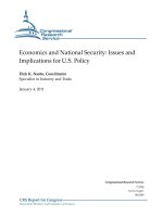
The Protocol Stack
cdma2000 takes the information
—
user data and signaling
—
from
the higher layers and adds two lower-layer protocols before trans-
Chapter 4
140
ferring the data over the air interface. This is shown in Figure 4-9.
The link layer consists of the link access control (LAC) and media
access control (MAC) layers. The MAC layer is divided into two sub-
layers: the physical layer-independent convergence function (PLICF)
and physical layer-dependent convergence function (PLDCF) [7], [5].
The various layers and sublayers perform the following functions.
Each traffic type coming from the higher layer has a different QoS
requirement in terms of delays, delay variations, and error rates. The
function of the LAC is to ensure that various types of traffic are
transferred over the air interface according to their QoS require-
ments. The link layer protocols used for this purpose include an auto-
matic repeat request (ARQ) as well as an acknowledged data transfer
procedure using acknowledgment/negative acknowledgment (ACK/
NACK) and sequence numbering for retransmission. The MAC layer
also provides a certain degree of transmission reliability. However,
when it does not meet the requirements of an application, the LAC
may call for an appropriate link layer procedure. Notice that for
some traffic, such as circuit-switched voice, the LAC layer function
may be null. In other words, associated packets from the higher lay-
ers are passed directly to the MAC layer.
141
cdmaOne and cdma2000
Packet
Data
Voice
over IP
Voice
Circuit
Data
Signaling
Link Access Control
PLICF
PLDCF
Physical Layer
MAC
Layer
Link Layer
Figure 4-9
The lower layer
protocols for
cdma2000
A MAC sublayer performs the following functions:
■ It controls user access to the physical layer (that is, the
medium) by resolving, if necessary, contention among multiple
applications from the same user or among multiple users, and
scheduling its resources so as to ensure efficient utilization of
bandwidth. Resources include buffers, spreading codes,
convolutional encoders, and so on.
■ User data and signaling information from the upper layers (that
is, the LAC layer and the higher layers) are multiplexed,
mapped into different physical channels, and delivered to the
physical layer on a best-effort basis, providing a basic level of
transmission reliability.
8
The MAC layer is divided into two sublayers:
■ Functions that are independent of the physical layer, such as
controlling access to the medium so as transmit packets, are
performed by the sublayer called PLICF. The user data and
control information are passed to the lower sublayer over a set
of logical channels, such as a dedicated traffic channel, common
traffic channel, dedicated signaling channel, common signaling
channel, dedicated MAC channel carrying MAC messages,
forward common MAC channel, and reverse common MAC
channel.
■ The second sublayer is the PLDCF. Functions performed at this
sublayer when transmitting over the air interface include
multiplexing logical channels coming from PLICF, mapping
them into physical channels, assigning proper priorities to each
according to its QoS requirement, and delivering them to the
physical layer. The best-effort delivery of data services is
performed at this layer using a radio link protocol (RLP) for
streaming-mode user data, and a radio burst protocol (RBP) for
Chapter 4
142
8
In the best-effort service, the user specifies the maximum and minimum data rates.
The amount of bandwidth allocated to a user may vary during the life of a call depend-
ing on the congestion experienced by the network.
short bursts of user data over a common traffic channel. The
RLP uses an ARQ-based retransmission scheme. The
corresponding protocols for handling signaling information are
the signaling radio link protocol (SRLP) and signaling radio
burst protocol (SRBP).
Physical Channels
Forward Physical Channels As in IS-95, the pilot channel con-
tinuously transmits a carrier modulated with an all-zero patttern so
that mobile stations can achieve initial cell synchronization. A
mobile station may use the received signal as a reference carrier for
coherent demodulation, or measure the received signal strength and
report the measurement to a base station for handoff purposes.
A common auxiliary pilot channel has been added to cdma2000 so
that adaptive antennas can be used for beamforming to extend cov-
erage, increase capacity, and provide higher data rates, among other
things. Because beamforming is accomplished by combining signals
from different locations in the antenna’s aperture in an optimal
manner using an adaptation algorithm that requires as accurate a
channel estimate as possible, it is necessary that the pilot and data
signals travel along the same path to the receiver [3], [4].
A dedicated auxiliary pilot channel is dedicated to a given mobile
station (or a group of mobile stations) for the purpose of beam steer-
ing using an adaptive antenna array.
A sync channel operates at 1200 b/s, transmitting synchronization
messages so that mobile stations in the coverage area of a base sta-
tion can acquire frame synchronization after cell acquisition. For a
single carrier system with a channel bandwidth of 1.25 MHz, the
channel encoder used is of rate
1
/
2
. If the system consists of multiple
carriers or a single carrier with a bandwidth of 5 MHz or more, the
convolution code used is of rate
1
/
3
.
The paging channel is used to transmit paging and overhead mes-
sages directed to mobile stations in the coverage area of a base
station. There are two data rates: 9.6 and 4.8 kb/s. For a single
carrier system with a channel bandwidth of 1.25 MHz, the convolu-
tional encoder used is of rate
1
/
2
. If the system consists of multiple
143
cdmaOne and cdma2000
carriers, or a single carrier with a bandwidth of 5 MHz or more, the
encoder used is of rate
1
/
3
.
The quick paging channel has been added so that a base station
can send a quick paging message to a mobile station operating in the
slotted mode. This message actually consists of a single bit, which is
followed by a regular paging message in the slot that has been allo-
cated to the particular mobile.
Next is the broadcast common channel. Instead of combining over-
head and paging messages on a paging channel, the system perfor-
mance can be improved to some extent by separating overhead
messages and sending them over this channel.
The common control channel is used to send layer 3 and MAC
layer messages to mobile stations at 9.6 kb/s using frame sizes of 5,
10 or 20 ms.
The dedicated control channel is similar to the common control
channel, but uses frames that are 5 or 20 ms long.
The fundamental channel is used for lower data rates: 9.6 kb/s
and its subrates, grouped as rate set 1, and 14.4 kb/s and its sub-
rates, grouped as rate set 2.
9
This channel is supported in both
single-carrier and multicarrier cdma2000 systems. Both 20 ms and
5 ms frames are permissible.
Supplementary channel 1 and 2 are designed for higher data
rates. Rates supported are shown in Table 4-1. Frames are usually
20 ms long.
Reverse Physical Channels The reverse pilot channel is similar
in concept to the forward pilot channel. Used in conjunction with
reverse dedicated channels, it enables a base station to acquire ini-
tial time synchronization and recover a phase-coherent carrier for
coherent demodulation in a rake receiver. It also includes a power
control subchannel, which sends one bit in each 1.25 ms power con-
trol group or 16 bits in each 20 ms frame. The base station can use
this bit to adjust its power level when necessary.
Chapter 4
144
9
This is after adding the frame quality indicator bits to incoming frames.
TEAMFLY
Team-Fly
®
The access channel transmits layer 3 and MAC layer messages
from different mobile stations to a base station. Multiple users
access this channel using a mechanism that is very similar to the
slotted Aloha scheme. The data rate supported is 9.6 kb/s. There may
be more than one access channel, each identified by a unique orthog-
onal code.
The common control channel, like the reverse access channel just
described, also carries layer 3 and MAC messages, and is accessed by
mobile stations using the same multiple access scheme. Data rates
supported include 9.6, 19.2, and 38.4 kb/s.
The dedicated control channel, like the reverse fundamental or
supplementary channels, carries user data packets at 9.6 kb/s or
14.4 kb/s in 5 ms or 20 ms frames.
The fundamental channel is similar to the forward fundamental
channel. It supports a data rate of 9.6 kb/s and its subrates (4.8,
2.7, and 1.5 kb/s), or 14.4 kb/s and its subrates (7.2, 3.6, and 1.8
kb/s). For these rates, convolutional codes are used. A frame is usu-
ally 20 ms long. However, in some cases, a 5 ms frame may also be
used. Note that only a fundamental channel supports a 5 ms
frame.
Supplementary channel 1 and 2, which are similar to the forward
supplementary channels, provide higher data rates: (1) 9.6, 19.2,
145
cdmaOne and cdma2000
Rate Set 1 Rate Set 2
Single-carrier cdma2000 M ϫ 9.6 kb/s, M ϭ 1, 2, M ϫ 14.4 kb/s, M ϭ 1, 2,
with a bandwidth of 4, 8, 16, and 32. Uses 4, 8, and 16. Uses
1.25 MHz channel encoder of channel encoder of
rate
1
/
2
. rate
1
/
2
.
Multicarrier cdma2000 M ϫ 9.6 kb/s, M ϭ 1, 2, M ϫ 14.4 kb/s, M ϭ 1, 2,
where each channel has 4, 8, 16, 32, and 64. 4, 8, 16, 32, and 64.
a bandwidth of 1.25 Uses channel encoder Uses channel encoder
MHz, or a single-carrier of rate
1
/
3
. of rate
1
/
4
.
system with a bandwidth
of 5 MHz or multiples
thereof
Table 4-1
Data rates
supported on a
supplementary
channel in
cdma2000
38.4, 76.8, and 153.6 kb/s, and (2) 14.4, 28.8, 57.6, 115.2, and 230.4
kb/s. Only 20 ms frames are supported. For these data rates, turbo
coding may be used.
Forward Channel Transmit Functions
As an aid to understand the technology used in the implementa-
tion of physical layer functions of a typical W-CDMA system, a sim-
plified block diagram of the transmit functions of a multicarrier
cdma2000 base transceiver station was presented in Chapter 3,
“Principles of Wideband CDMA,” (see Figure 3-5 of that chapter).
Figure 4-10 shows a similar diagram of the transmit functions of
the forward channels of a direct-spread, single-carrier cdma2000
system. For simplicity, only a subset of the forward physical chan-
nels is included in this figure. Notice the similarity between
cdma2000 and IS-95 (refer to Figure 4-4) forward channel transmit
functions. Some of the differences are as follows.
cdma2000 has two traffic channel types
—
the fundamental and
secondary. A number of data rates are supported. Depending upon
the data rate, convolutional codes of rate
1
/
2
,
3
/
8
,
1
/
3
, or
1
/
4
may be used.
Both 10 ms and 5 ms frames are supported.
I- and Q-channel symbols are multiplied by gain factors
to provide some additional power control. As in IS-95, cells are
separated by different pilot PN sequence offsets.
10
However, now,
complex spreading is used by, first, adding the real-valued I and Q
sequences in quadrature (so that the result is a complex number)
and then multiplying it with a another complex number S
I
ϩ jS
Q
,
where S
I
and S
Q
are, respectively, the I-channel and Q-channel pilot
PN sequences. The output of this multiplication is a complex quan-
tity whose in-phase and quadrature components are as shown in the
lower part of the figure. With complex spreading, the output of the
wave-shaping filter goes through zero only with low probability, thus
leading to improved power efficiency.
Chapter 4
146
10
The period of these sequences is 2
15
Ϫ 1 chips.
Reverse Channel Transmit Functions
The functional block diagram of direct-spread, reverse-channel
transmit functions in cdma2000 is shown in Figure 4-11. Consider,
first, the fundamental channel. The incoming data on this channel is
processed in the usual way. Depending on the user data rate, a vari-
able number of frame-quality indicator bits in the form of CRC are
added to a frame. A few tail bits are appended to ensure proper oper-
ation of the channel encoder, which may be either a convolutional
147
cdmaOne and cdma2000
W0
X
X
X
X
carrier
W
Q
Complex
Spreading
Code
Walsh Code for
Paging Channel
Block
Interleaver
Paging
Channel
Wave-Shaping
Filter
X
X
t
A
cos
Output
Symbol
Mapper
IS QS
IQ
QS IS
IQ
k = 9
r = 1/2
Symbol
Repettion
Paging Channel
Long Code Mask
Long Code
Generator
Decimator
+
o
o
MUX
P/S
I
Q
Channel
Gain
Channel
Gain
X
X
j
I
QI
jSS
+
Pilot Channel
Convolutional
Encoder
Block
Interleaver
Sync
Channel
k = 9
r = 1/2
Symbol
Repettion
+
Walsh Code for
Sync Channel
+
Block
Interleaver
Fundamental or
Secondary
Channel
Conv.
Encoder
Symbol
Repettion
Long Code Mask
Long Code
Generator
Decimator
+
Add CRC
and
Encoder
Tail Bits
A
B
C
D
A
D
Decimator
PC Bits
MUX
carrier
W
Wave-Shaping
Filter
t
A
sin
ω
∑
∑∑
−
+
+
Figure 4-10
The functional
block diagram of
direct-spread
(single-carrier)
forward channel
transmit functions
in cdma2000
coder or a turbo coder. Code symbols are repeated, but depending
upon the rates, some of them are also deleted. The output of the
interleaver is spread with a Walsh code, mapped into modulation
symbols, and multiplied by gain factors, resulting in a signal labeled
A
fund
.
The supplementary channels 1 and 2 and control channels are
processed in the same way, although details might vary in some
cases. For example, symbol puncturing is not done on a reverse ded-
icated control channel. Similarly, the reverse pilot channel, which
consists of a string of zeros (that is, real values of ϩ1), is treated dif-
ferently because it is not encoded into a channel code, interleaved in
a block interleaver, or multiplied by a Walsh code. However, a power
control bit is inserted into the pilot channel for each power control
group or 16 power control bits per frame. For simplicity, we have
omitted these repetitions and merely indicated the processed out-
puts of these channels as A
sub1
, A
sub2
, A
cont
, and A
pilot
.
The fundamental channel and supplementary channel 1 are
summed together giving an output Q. Similarly, the remaining chan-
nels are summed separately, giving I as the output. Notice that in
this case, the I- and Q-channel sequences formed for QPSK modula-
tion are independent of each other because they are derived from dif-
ferent channels and not by splitting the data stream of a given
Chapter 4
148
Wave-Shaping
Filter
X
X
t
A
cos
IS QS
IQ
Ϫ
QS IS
IQ
ϩ
I
S
Reverse
Fundamental
Channel
Conv. or
Turbo
Encoder
User m
Long Code
Mask
+
Add CRC
and
Encoder
Tail Bits
Wave-Shaping
Filter
t
A
sin
Symbol
Mapper
Walsh
Code
Gain
Symbol
Repettion &
Puncture if
Needed
Interleaver
fund
A
1sup
A
2sup
A
cont
A
pilot
A
I
Q
Complex
Spreading
I
Q
I-Channel
PN Sequence
Q-Channel
PN Sequence
Walsh Code
Q
S
Complex Code
Generator
⌺
⌺
⌺
Figure 4-11
The functional
block diagram of
direct-spread
reverse channel
transmit functions
in cdma2000
channel into two sub-streams. The I and Q sequences are spread by
a complex code of the type S
I
ϩ jS
Q
, where S
I
and S
Q
are user-specific
because they are obtained from a 42-bit long code mask for the given
user, I- and Q-channel pilot PN sequences, and a Walsh code.
Summary
In this chapter, we have described the fundamental aspects of
cdma2000, which is one of the systems specified by IMT-2000.
Because cdma2000 is an evolved version of the current CDMA sys-
tem known as cdmaOne, a brief description of this system is also
included. The basic features and service capabilities of cdma2000 are
discussed. To provide services in cdma2000, a new link layer proto-
col has been defined that consists of a LAC layer and a MAC layer.
The functions performed by the different sublayers are briefly
described. This is followed by a description of the physical layer in
terms of the physical channels and the forward and reverse channel
transmit functions.
The distinctive features of a cdma2000 system may be summa-
rized as follows:
■ Wider bandwidth and higher chip rate For a direct-spread
CDMA system, the nominal bandwidth is 5 MHz. While IS-95B
supports data rates in the range of 64 to 115 kb/s, much higher
data rates
—
from 144 kb/s to 2.0 Mb/s
—
are possible in
cdma2000. CDMA in general is inherently resistant to fades.
However, the improvement in the bit error rate performance is
significantly greater for a 5 MHz system than for 1.25 MHz.
Because the chip rate is three times as high as in IS-95, for a
given power delay profile, there are many more resolvable paths
in direct-spread cdma2000 that can be utilized in a rake
receiver. Furthermore, as we discussed before, transmit diversity
is a distinct possibility here that will significantly improve the
downlink performance.
■ Multicarrier system cdma2000 may consist of a single, direct-
spread, 5 MHz carrier, or multiple carriers, each with a
149
cdmaOne and cdma2000
bandwidth of 1.25 MHz. In a multicarrier system, because each
carrier is orthogonally spread, W-CDMA can be overlaid on an
existing IS-95 system. Also, a multicarrier system is inherently
capable of providing transmit diversity because high-speed user
data may be divided into two or more streams and transmitted
on multiple carriers over different antennas.
■ Spreading codes In both IS-95 and cdma2000, the spreading of
downlink channels is similar. For example, different cells are
separated by means of different offsets of the I- and Q-channel
pilot PN sequences. Similarly, traffic channels directed to a given
user are spread by user-specific long codes.
On uplinks, however, there are some differences. In cdma2000,
physical channels are separated by Walsh codes, and mobile
stations by long codes, whereas in IS-95, long codes are used to
separate the access and traffic channels.
■ Variable length Walsh codes Because a traffic channel of a
cdma2000 system is required to support many data rates, it is
necessary to use variable-length Walsh codes. This length varies
from 4 to 128 chips. On fundamental channels, Walsh codes
have a fixed length. But on the secondary channels, as the data
rates increase, the code length decreases (which, in essence,
reduces the process gain and thus the number of simultaneous
users on a CDMA channel).
■ Complex spreading In cdma2000, complex spreading is used
that reduces the amplitude variations of the baseband filter
output, thus making the signal more suitable for nonlinear
power amplifiers.
■ Additional pilot channels Many new physical channels have
been defined in cdma2000 that have the potential for improving
the system performance. For example, in the downlink, there is
an auxiliary pilot that may be code-multiplexed to provide
beamforming and beam steering with adaptive antenna arrays.
Similarly, there is a pilot channel in the uplink, which again is
code-multiplexed, enabling a base station to recover the carrier
for coherent demodulation in a rake receiver.
Chapter 4
150
■ New traffic channels There are two types of traffic channels:
fundamental and supplementary, both of which are code-
multiplexed. A fundamental channel is used for lower data rates
such as 9.6 and 14.4 kb/s and their subrates. The supplementary
channels provide higher data rates. Also, two channel codes are
used
—
convolutional codes on fundamental channels or
supplementary channels with a data rate of 14.4 kb/s. At higher
data rates on a supplementary channel, turbo codes of constraint
length 4 and rate
1
/
4
are recommended. Fundamental channels
support both 20 ms and 5 ms frames, while secondary channels
use only 20 ms frames.
■ Packet mode data services cdma2000 supports a highly flexible
packet mode data service. The multiple-access procedure is
based upon the slotted Aloha scheme. The physical channels that
may be used for this purpose include dedicated traffic channels,
dedicated control channels, and common control channels.
■ Quality of service The support of multimedia services at
variable data rates with user-specified QoS is unique to
wideband systems.
References
[1] T. Ojanpera and R. Prasad, “An Overview of Air Interface
Multiple Access for IMT-2000/UMTS,” IEEE Commun. Mag.,
Vol. 36, No. 9, September 1998, pp. 82–95.
[2] E. Dahlman, B. Gudmundson, M. Nilsson, and J. Skold,
“UMTS/IMT-2000 Based on Wideband CDMA,” IEEE Com-
mun. Mag., Vol. 36, No. 9, September 1998, pp. 70–80.
[3] F. Adachi, M. Sawahashi, and H. Suda, “Wideband DS-CDMA
for Next Generation Mobile Communications System,” IEEE
Commun. Mag., Vol. 36, No. 9, September 1998, pp. 56–69.
[4] G. Tsoulos, M. Beach, and J. McGeehan, “Wireless Personal
Communications for the 21st Century: European Technolog-
ical Advances in Adaptive Antennas,” IEEE Commun. Mag.,
Vol. 35, No. 9, September 1998, pp. 102
—
109.
151
cdmaOne and cdma2000
[5] TIA TR 45.5, “The cdma2000 ITU-RTT Candidate Submis-
sion,” TR 45-ISD/98.06.02.03, May 15, 1998.
[6] TIA/EIA/IS-95-A: Mobile Station-Base Station Compatibility
Standard for Dual-Mode Wideband Spread Spectrum Cellu-
lar System, May 1995.
[7] V.K. Garg, IS-95 CDMA and cdma2000. New Jersey: Prentice
Hall, 1999.
Chapter 4
152
The GSM
System and
General Packet
Radio Service
(GPRS)
CHAPTER
5
5
Copyright 2002 M.R. Karim and Lucent Technologies. Click Here for Terms of Use.
We mentioned in Chapter 1 that core networks of UMTS are har-
monized with GSM. The UMTS core network is also compliant with
the Mobile Application Part (MAP) protocol of Signaling System 7
(SS7) that provides signaling between a Mobile Switching Center
(MSC), the Visitor Location Registers (VLR), the Home Location
Register (HLR), and the Authentication Center (AC) in GSM. Simi-
larly, the packet mode data services in UMTS and the associated
network entities and protocols have been harmonized with those of
GPRS, which is now being offered as an upgrade of GSM. The reader
may recall from Chapter 1 that ETSI has also defined another stan-
dard called Enhanced Data Rates for GSM Evolution (EDGE) to
support data rates up to 384 kb/s in GSM networks. The wideband
TDMA system IS-136 HS for outdoor/vehicular applications is
designed to use this protocol in the access network. Thus, even
though there are significant differences in the air interface stan-
dards of UTRAN and GSM, a description of GSM and GPRS is
appropriate in this context.
GSM was first deployed in a few countries of Europe in 1991. Sub-
sequently, it was adopted in most of Europe, Australia, much of Asia,
South America, and the United States. Today, it is the fastest grow-
ing technology in many parts of the world and is being continually
evolved to provide advanced features, particularly in areas of data
communications.
GSM supports voice, circuit-switched data, and short messaging
services. The standards work on a packet mode data service in GSM
started in 1994, and was completed in 1997. The new system speci-
fied by these standards was called GPRS. A number of references are
available in the literature that describe the GSM system in great
detail. See, for example, [23], [1], and [2]. Reference [9] gives a
detailed description of GPRS and discusses its performance based on
simulation. GPRS services are described in [11]. An overall descrip-
tion of the GPRS radio interfaces appears in Reference [12]. Details
of the radio link control and medium access control protocols are pro-
vided in Reference [13]. Our goal in this chapter is to present an
overview of GSM and GPRS systems.
Chapter 5
154
TEAMFLY
Team-Fly
®
GSM System Features
GSM operates in the frequency division duplex mode, using one band
for uplinks and a separate one for downlinks. Initially, a 50 MHz
bandwidth around 900 MHz was allocated to GSM. The spectrum
allocation is shown in Figure 5-1. The 25 MHz spectrum in either
direction is divided into 125 physical channels, each with a band-
width of 200 kHz. To avoid interference with other systems operating
at the edges of the GSM spectrum, one of these channels is not used.
Later, a second allocation of 150 MHz bandwidth centered around
1800 MHz was set aside for use in systems called Digital Cellular
System at 1800 MHz (DCS1800).
1
In GSM, speech is digitally encoded at 13 kb/s using linear pre-
dictive coding (also known as vocoding). Information is transmitted
in frames, each 4.615 ms long and divided into eight equal time slots.
Normally, each slot is assigned to a user. Data (such as voice sam-
ples) from multiple users is time-division multiplexed on a frame and
sent out over a physical channel at 270.8333 kb/s. Because each
channel operates at a different frequency, the system combines
TDMA with frequency division multiple access (FDMA). The GSM
characteristics are summarized in Table 5-1.
155
The GSM System and General Packet Radio Service (GPRS)
915
Downlink
890 935 960
Uplink
Frequency
(MHz)
200 kHz
Paired Channels
900.2 945.2
Figure 5-1
Spectrum
allocation for GSM
1
The allocation is 1710 to 1785 MHz for uplinks and 1805 to 1880 MHz for downlinks.
Among the features and capabilities of GSM are the following:
■ Teleservices This includes regular telephony via public switched
telephone networks (PSTN), emergency calling such as police or
fire brigade, and voice messaging where a calling party can leave
a voice message that can be retrieved later by the called party.
■ Bearer services These include data services and short
messaging services. For data services, the MSC may be
connected to a circuit-switched PSTN via a modem or to a public
data network via a packet assembler and disassembler (PAD). A
mobile station may subscribe to circuit-switched data services at
all standard rates up to 9.6 kb/s without having to use a modem
Chapter 5
156
Multiple Access Scheme TDMA/FDMA with FDD
Spectrum allocation 890
—
915 MHz (uplink), 935
—
960 MHz
(downlink)
Bandwidth of each 200 kHz
physical channel
Total number of channels 124
available in either direction
Number of users per channel 8
Data rate 270.83333 kb/s, bit period ϭ 3.692 ms
TDMA frame size 4.615 ms
Number of slots per frame 8
Slot duration 0.576923 ms
Modulation 0.3 GMSK
Speech coding 13 kb/s Regular Pulse Excitation with Long
Term Predictor (RPE-LPT)
Interleaver period 40 ms maximum, using two consecutive
20 ms blocks of data
User data transfer capability Short messaging service, circuit-switched
data, high-speed circuit-switched data, and
GPRS for packet data
Table 5-1
Summary of GSM
system
characteristics
and should also be able to access public data networks at 9.6
kb/s, 4.8 kb/s, and 2.4 kb/s.
In GSM, a mobile station is permitted to transmit or receive
short messages during both idle and active call states. A message
may contain up to 160 alphanumeric characters. Shorter
messages with only 93 characters may be broadcast by a base
station to all mobiles in a serving area. A subscriber may dictate
a message at a service center, which may later be sent to the
intended party. If the intended party is not available, the
message is saved and later forwarded when the party is
available.
■ Supplementary services These include private branch exchange
(PBX) features such as call forwarding, call hold, call waiting,
call transfer, calling number identification, detailed billing
records, three-party conference calls, interoperability with ISDN,
and so on.
Other important features, not necessarily in the order of their
importance, include international roaming in European countries,
secure communication and privacy, use of a subscriber identity mod-
ule (SIM) to distinguish between the identity of a subscriber and
that of the mobile station, and discontinuous transmission (DTx),
that is, turning off the transmitter during silence periods, thus lead-
ing to increased battery life.
A new feature that is available with the later version of GSM,
known as Phase 2ϩ, is the GPRS, whereby both high-speed and low-
speed user data and signaling information may be transferred using
packet-switching techniques. In this service, a single time slot may
be shared by multiple users for transmitting data in the packet
mode, resulting in a throughput of about 12 to 20 kb/s. Thus, if all 8
slots of a frame are used, it is possible to achieve a throughput of
about 124 to 171 kb/s.
System Architecture
The GSM system architecture is shown in Figure 5-2. The air inter-
face corresponds to the reference point Um between a mobile station
157
The GSM System and General Packet Radio Service (GPRS)
(MS) and a base transceiver station (BTS). Each cell is served by a
BTS that consists of multiple radio receivers and transmitters. Base
station controllers (BSC) perform radio control functions such as
power control and handoff. Each BSC may connect to one or more
BTS over the A-bis interface. There may be one or more base station
controllers in a serving area. BTSs and the associated BSCs for a
given area are together known as a base station subsystem (BSS).
The MSC is responsible for call controls, call routing to and from
PSTNs, and switching and controls during a handover process. It
connects to a BSS over the A interface. It interfaces with a number
of other entities: VLR, HLR, Equipment Identity Register (EIR), and
Operations and Maintenance Center (OMC). It also requires the ser-
vices of the AC, which is connected to the HLR. A brief description of
each of these entities is given in the following paragraphs.
The HLR is a database system of all mobile subscribers who are
registered in a public land mobile network (PLMN). There may be
just one HLR at a central location in a network or many of them dis-
tributed throughout the network, but only one of them contains the
information about a given subscriber. The VLR contains the data-
base of all mobile subscribers who are visiting this particular serving
area. There is a VLR for each serving area controlled by an MSC.
Whenever a mobile travels into a foreign serving area, the VLR of
the visited system requests the database of that mobile from its HLR
and saves it in its memory so that it can continue to serve that
mobile as long as it is in this area. At the same time, the MSC of this
Chapter 5
158
PSTN/ISDN
BTS
o
o
o
BTS
IWF
BTS
BSC
BSC
o
o
VLR
HLR
AC
EIR
MSC
A
Interface
A-bis
Interface
BSS
OMC
MS
Um (Air
Interface)
Figure 5-2
GSM system
architecture
foreign serving area informs the HLR of the home system about the
location of this mobile so that the home area of this subscriber can
route the call correctly when necessary.
The authentication center verifies the identity of the user at call
inception times for security purposes, and contains such parameters
as authentication keys and other required parameters. The EIR con-
tains the International Mobile station Equipment Identity (IMEI)
numbers of all mobile stations that are registered. Each mobile is
assigned a unique IMEI number that can be used to determine
whether the equipment is genuine or not. The OMC is a centralized
network management system that provides the capability of remote
system administration and maintenance of all equipment and data-
bases, and may also perform such functions as billing and so on.
Figure 5-3 shows the functional block diagram of a GSM system.
A brief description of the system is presented here. Each functional
block will be further explained in the next section.
Figure 5-3(a) represents the transmitter of a mobile station. The
speech signal from a mobile terminal is encoded into 13-bit uniform
pulse code modulation (PCM) samples and applied to the input of a
RPE-LTP coder [1]
—
[5]. It is in fact a linear predictive coder, or a
vocoder as it is called, that attempts to predict the incoming speech
by modeling the speech-generating system by a finite-order, time-
varying digital filter.
2
The RPE-LTP encoder actually consists of two
159
The GSM System and General Packet Radio Service (GPRS)
Speech from
Mobile Station
13-bit PCM
Encoder
RPE-LTP
Encoder
Channel
Coder
Interleaver
GMSK
Modulator
Up Converter
& Power
Amplifier
Amplifier &
Demodulator
Deinterleaver
Channel
Decoder
13-bit PCM
to 8-bit A-
law Encoder
To MSC
RPE-LTP
Decoder
RF Input at
Base Station
(a)
(b)
Data
Speech
Figure 5-3
The functional
block diagram of a
GSM system
2
In other words, the vocoder tries to mimic the vocal system of a human being. See
References [1] to [5].
linear predictive filters, and generates a residual excitation (that is,
a difference signal between the incoming speech and predicted
speech), which is multiplexed with the coefficients of the two filters
and passed to the channel encoder. Because there are 260 bits at the
output of the encoder for every 20 ms of the speech input, the bit rate
of a full-rate coder is 13 kb/s.
The purpose of the channel encoder is to provide some protection
against impairments that are likely to be introduced by the channel.
This is done by encoding the incoming frames into error-correcting
codes. GSM uses a combination of block codes and convolutions
codes. An (n, k) block code encodes a k-bit message block into an n-bit
code by adding n Ϫ k parity bits. A convolutional code of rate
1
/
2
with
a constraint length of 5 is used for speech. For 9.6 kb/s data, convo-
lutional codes are the same, but a few bits are deleted from each
frame (resulting in punctured codes) so as not to exceed the data rate
of the physical channel. If the data rate is 2.4 kb/s, the convolutional
code is rate
1
/
6
,
but has the same constraint length. Not all bits of the
speech encoder output are equally critical to the subjective quality of
speech at the receiver. Bits that are most essential to intelligibility of
speech are protected against channel errors by encoding them into
both block codes and convolutional codes. If there are any errors in
these bits that the receiver cannot correct, they are discarded. Bits
that are less critical are encoded into convolutional codes only. The
remaining bits are transmitted without any channel coding. A 20 ms
frame at the output of the channel encoder contains 456 bits.
The output of the channel encoder is applied to an interleaver,
which simply rearranges the order of the incoming bits.
3
As men-
tioned previously, speech or data is transmitted in frames, as shown
in Figure 5-4. Each frame consists of eight slots, each of which is
assigned to an individual user. Later on, we will see how exactly the
data structure of a slot is constructed. For the time being, though, it
is sufficient to say that each slot contains 114 bits of the interleaver
output and 42.5 bits of overhead.
Chapter 5
160
3
Correlated signal fading, which is a characteristic of a mobile radio channel, results
in burst errors. The purpose of the interleaver is to spread out in time these burst
errors so that the receiver can detect and correct them with a higher probability.
Notice that the data rate at the output of the interleaver is the same as the input.