INTRODUCTION TO URBAN WATER DISTRIBUTION - CHAPTER 5 pot
Bạn đang xem bản rút gọn của tài liệu. Xem và tải ngay bản đầy đủ của tài liệu tại đây (4.93 MB, 20 trang )
CHAPTER 5
Network Construction
Network construction comprises the following steps:
1 site preparation,
2 excavation,
3 trench dewatering,
4 pipe laying,
5 jointing,
6 backfilling,
7 testing & disinfection.
After the site has been prepared, all the other steps are conducted simul-
taneously at various sections of the pipe route; at its end, the pipes are
tested; a few pipes further, the backfilling takes place; and at the same
time at the preceding section the pipes are jointed, etc. This coordinated
method of working is important in order to shorten the total duration of
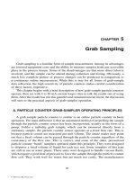
the construction, reducing both the cost and disturbance. The laying of a
few sections of steel pipe is shown in Figure 5.1.
Pipes can also be laid above ground or in tunnels, which then require
adapted laying techniques such as the use of casings, anchorages and
supports, etc. Some typical principles and solutions are briefly presented
in this chapter.
Figure 5.1. Laying of steel pipe.
© 2006 Taylor & Francis Group, London, UK
Network Construction 207
5.1 SITE PREPARATION
Pipes can be laid only when the route is completely clear. Site preparation
in urban areas can be a complex task where cooperation with other utili-
ties is very important. Works on water, electricity, gas, road or other
infrastructure are often carried out simultaneously.
Before the work can commence, mutual agreement should be
obtained about the working area so that other daily activities are not
significantly affected during the construction. Proper signalling, foot-
paths and crossings for pedestrians, signs and warnings, a restricted
access to the equipment in operation etc. must be provided during the
entire period of work.
Pipes will be tested prior to leaving the factory and should also be
tested after reaching the site in order to check for possible damage result-
ing from transportation. Further damage to the pipe is possible during
the process of unloading, stacking and/or stringing along the laying
route. The dropping of pipes, pipes striking each other, bundling pipes
too high and stacking them on an uneven surface or without proper
support will all have a negative effect. Each scratch on the external or
internal coating of a metal pipe is a potential source of corrosion.
Cement-based pipes are very vulnerable to impact damage and plastic
pipes, although lighter, are not an exception in this respect; scratches on
PVC reduce the pipe strength. Hence, a final check is necessary for each
pipe before it is put into position.
Pipes and fittings waiting to be installed should be kept clean in a
fenced storage as a protection against potential theft and vandalism
(Figure 5.2).
Before excavating paved surfaces and roads, the cutting of edges of
the trench has to be done to avoid damage to surrounding areas. If traffic
Figure 5.2. Pipe storage on the
construction site.
© 2006 Taylor & Francis Group, London, UK
208 Introduction to Urban Water Distribution
loads allow, the pipe route will be located alongside the road, preferably
not too far from it, which reduces damage to the pavement resulting from
excavation. Breaking the surface is usually carried out by pneumatic
hammers. Large pieces of concrete and asphalt will be removed from the
site as they will not be used for backfilling. If the surface is not paved,
the topsoil is usually removed by scrapers and stacked for use in the final
reinstatement of the site.
5.1.1 Excavation
Excavation is the most expensive part of pipe laying. The choices of
technique and trench dimensions are therefore very important factors that
will affect the total cost. The preferred excavation method depends on
– available space on the site,
– soil conditions,
– width and depth of the trench.
Excavation is commonly carried out by mechanical excavators (Figure 5.3).
In areas where there are obstructions (e.g. other services are in the
trench) or access for the machine is restricted (small streets, busy traffic,
etc), excavation by hand might be required (Figure 5.4). For smaller
trenches (up to 300 mm wide and 1 m deep) vacuum excavation can be
used. After breaking the surface and removing the top layer in the
conventional manner, a special pneumatic digging tool is used. With this
method, the soil is then removed through a flexible hose.
Care has to be taken during the work:
– to stabilise the walls, either by battering or shoring,
– to clear the trench edges of chunks of rock or earth that could potentially
damage the pipe or hurt the workers,
– to leave enough space between the trench and pile of excavated material,
– to keep the work as dry as possible.
Figure 5.3. Mechanical
excavation in sand.
© 2006 Taylor & Francis Group, London, UK
Network Construction 209
Batter-sided trenches are rarely used in urban areas because of the space
needed. Where possible, the angle of slope should depend on the trench
depth and soil characteristics, as shown in Figure 5.5.
Different techniques of shoring can be applied by (Brandon, 1984):
1 prefabricated wooden panels (jointed or single),
2 wooden or metal sheets,
3 pile driven sheets.
The choice of technique, dependant on the soil conditions, is often pre-
scribed by laying regulations. Three groups of soils can be distinguished
regarding their suitability for excavation (see Figure 5.6).
Figure 5.4. Manually excavated
trench.
0 1 2 3 4 5 6 7 8 9 10
H (m)
Angle of
slope
φ
0
1000
2000
3000
4000
5000
q (kg/m
2
)
φ=25
°
φ=30
°
φ=
35
°
φ=
40°
Figure 5.5. Trench slopes
(Pont-a-Mousson, 1992).
© 2006 Taylor & Francis Group, London, UK
210 Introduction to Urban Water Distribution
Rocks Rocks are extremely cohesive materials but the possibility of collapse
cannot be excluded. Cracks are sometimes present, which can result in
rocks falling. Excavation is difficult in this type of soil.
Friable soils Friable soils are the most common soils. A certain degree of cohesion
allows them to hold together for a while during excavation. However,
these soils are very sensitive to water, and collapse of the trench walls
caused by the vibration of the equipment is also possible.
Non-cohesive soils Non-cohesive soils are soils without any cohesion (e.g. dry sand, mud or
freshly restored backfill), which collapse almost instantly. Protection
against the danger of collapse is therefore essential.
Shielding The shielding technique can be used in rocky and friable soils, in the
absence of shoring. By this method, the laying and jointing work takes
place in a partly open steel box that is pulled throughout the trench as the
work progresses. The sidewalls of the box do not prevent occasional
caving in of the soil, as the width of the box is smaller than the trench
width in order to be able to pull it smoothly. The main objective here with
this method is the protection of the workers.
How much trench is excavated depends on the time necessary for
pipe laying and backfilling. Normally, the trenching is excavated a day
or two ahead of the pipe laying, depending on the laying methods
applied. However this should not be carried out too far in advance, as
empty trenches may accumulate rainwater and are potentially dangerous,
especially outside working hours.
The width of the trench at the bottom depends on the pipe diameter.
An additional space of 0.3–0.6 m around the pipe (external diameter)
should be provided for shoring and jointing works.
Extreme temperatures can have an impact on the operation of water
distribution systems, not only by affecting the water consumption but
also by causing pipe damage either by freezing or very high tempera-
tures. While deciding on the optimal trench depth, care should be taken
to minimise the temperature impact on pipes and joints. On the other
Rocks Friable Non-cohesive
Figure 5.6. Soil types.
© 2006 Taylor & Francis Group, London, UK
Network Construction 211
hand, increasing the depth beyond what is really essential is more costly,
not only during installation but also in the maintenance phase. Some
degree of pipe burst under extreme weather conditions is always acceptable
if the repair can be conducted quickly and without disturbance to a
large number of consumers.
In general, the minimum cover over the pipe crown in moderate
climates are
– 1.0 m for transmission lines,
– 0.8 m for distribution pipes,
– 0.6 m for service pipes.
For frost prevention, pipes are laid deeper in areas with a cold climate,
sometimes up to 2.5–3 m, which depends on the degree of frost penetra-
tion in the ground. Alternatively, pipes in shallow trenches can be laid
with thermal insulation. In extremely hot climates, the pipes will also be
buried deeper, mainly to preserve the water temperature. Examples from
practice are shown in Table 5.1.
The excavated material is deposited alongside the trench if it is going to
be used for backfilling. Its location should not be too far from the trench
but also not too close, as it exerts pressure on the trench wall, risking its
collapse. Moreover, it also limits the movement of the workers. In general,
approximately 0.5 m space should be left free for deposited material.
Tunnelling Excavation for laying pipes passing under roads, railways and water-
courses is done by tunnelling. The special reason for this is to protect the
surrounding area from erosion caused by the pipe burst or leakage, which
can have catastrophic consequences. Second, the pipe is protected in this
way from soil subsidence and vibrations caused by traffic, and mainte-
nance can be carried out without interruptions or breaking of the surface.
Excavation of tunnels is a very expensive activity. In this situation
thrust boring is applied, whereby a rotating auger moving the excavated
material backward pushes a steel shield pipe forward. New lengths of
pipes are welded or jointed together as the tunnelling proceeds, finally
appearing at the other side of the crossing.
Cut and cover method The thrust boring technique is successful for short lengths of tunnels, up
to 100 m, and for pipes of maximum 2500 mm diameter (Brandon, 1984).
Table 5.1 Soil cover over pipes.
Country Depth (m)
Austria 1.0–1.5
Belgium 0.8–1.0
Finland 2.1–2.5
Germany 1.1–1.8
The Netherlands 0.8–1.0
Switzerland 1.2–1.5
© 2006 Taylor & Francis Group, London, UK
212 Introduction to Urban Water Distribution
For longer lengths and larger diameters, a tunnel should be constructed
by traditional methods. These structures can also serve to accommodate
several pipes, usually water mains carrying large quantities of water. In
rock, the tunnel section can be a vertical wall lined with concrete; for
other soils circular sections formed by reinforced concrete segments are
common. When the tunnel is shallow it can be constructed by the cut and
cover method and in this situation a reinforced concrete box culvert is a
more suitable solution.
5.1.2 Trench dewatering
The normal method of removing water as it enters the excavation is by
pumping (Figure 5.7). Sand and silt in unstable soils are mixed with
water and carried out as well. If this continues over a period of time,
there is a danger of subsidence in adjacent ground. In such situations, the
removal of ground water can be carried out by using well point dewater-
ing equipment (Figure 5.8). The water is collected through perforated
suction pipes put in the ground below the lowest excavation level. All
suction pipes are connected to the header pipe, which transports the
water by vacuum created by a well point pump. The equipment used for
this method is shown in Figure 5.9.
Figure 5.7. Trench dewatering
by pumping.
Shoring
Dry area
GW without pumping
Ground level
Perforated
probe
Pump Pump
GW with pumping
Figure 5.8. Principle of the well
point method.
© 2006 Taylor & Francis Group, London, UK
Network Construction 213
Although proven to be very efficient in the case of non-cohesive
soils, the well point dewatering method can rarely be used in impervious
soils because the water is not able to flow to the extraction points.
Electro-osmosis, forcing the water by means of a passage of electrical
current to a dewatering point, may be successful in maintaining vertical
sides in wet unstable silt.
5.2 PIPE LAYING
5.2.1 Laying in trenches
The trench bottom provides the pipe’s foundations. In homogeneous,
even and well-consolidated soils, pipes can be laid directly on the
bottom. The pipe should touch the ground surface with its entire length.
To facilitate this, the space around joints should also be excavated. In
rocky soils, a pipe bed of 15–20 cm should be provided (Figure 5.10).
Depending on the pipe material, the bed can be made of sand, gravel or
dry concrete, which assumes that the surface of the trench bottom is even
and well compacted
When it is necessary to lay on less stable ground, pipes should be sup-
ported on piles based on a stable material, if such materials is to be found
at a depth less than 1.5 m. Care should be taken to avoid point loads being
transmitted to the pipes (particularly in the case of PVC pipes).
Figure 5.9. Application and
equipment for the well point
method.
Pipe bed:
fine gravel
or sand
Figure 5.10. Pipe bed.
© 2006 Taylor & Francis Group, London, UK
214 Introduction to Urban Water Distribution
Piles can also provide support to the pipes in waterlogged grounds. If
this is not sufficient, lowering the ground water table can be achieved by
laying a drain alongside the trench at a depth of 0.5 m below the pipe
invert. The pipe is bedded on the reinforced concrete raft placed across
the trench bottom, which ensures its stability. An example of concrete
transportation pipes laid on wooden piles is shown in Figure 5.11.
Most pipes are still laid individually in the trench. With the increased
use of flexible pipes, the technique of laying large sections of distribution
mains is becoming more common. The placing of pipes on the prepared
bed in a position ready for jointing requires appropriate equipment and
skill (Figures 5.12 and 5.13). The precise laying procedure depends on the
Cross
section
Normal route Crossing under a road
Wooden support
30 x30 x150 cm
240 cm
110 cm110 cm
5cm
125 cm 200 cm 200 cm 75cm150 cm 300 cm 150 cm
Figure 5.11. Pipes laid on
wooden piles.
Figure 5.12. Testing of external
coating.
© 2006 Taylor & Francis Group, London, UK
Network Construction 215
pipe material; the advice of pipe manufacturers must be taken into
account here. The entering of ground- or rainwater into the pipeline is
highly undesirable, so pipe stoppers should be used if the work has to be
halted, for example, at the end of the day. In highly corrosive ground,
metal pipes (and joints) can be sleeved into a polyethylene film at the
time of laying as an additional protection to the external coating, as
shown in Figure 5.14.
5.2.2 Casings
Different principles of casings are possible; two methods are shown in
Figures 5.15 and 5.16.
Old pipes can sometimes be used as casings for the new pipes
(Figure 5.17). This solution will probably reduce the maximum capacity
of the line, although the smaller diameter is partly compensated for
by the decreased roughness values of the new pipe. Special care should
be paid to the jointing of the new pipes in order to make the route
leakage free, as there is little space for any possible future repairs or
maintenance.
5.2.3 Laying above ground
The following aspects should be considered when laying pipes above
ground:
1 the design of the support system,
2 the accommodation of thermal expansion,
3 the anchorage of components subjected to hydraulic thrust,
4 protection against freezing (where necessary).
Figure 5.13. Pipe positioning in
a trench.
© 2006 Taylor & Francis Group, London, UK
216 Introduction to Urban Water Distribution
Joint sleeve
Soil
Plastic coated
fastenings
Adhesive tapes
Joint sleeve
Figure 5.14. Protection of pipes
and joints (Pont-a-Mousson,
1992).
© 2006 Taylor & Francis Group, London, UK
Network Construction 217
Some examples of the laying of DI pipes in tunnels and crossings are
shown in Figures 5.18–5.20.
Figure 5.16. Pipe casing (Pont-a-Mousson, 1992).
Casing
Pulling rope
Tackle for assembly
Hydraulic jack winch
Guidance
Weld bead
Hydraulic unit
SpoolsCasing Anchoring
cable
Guidance collar
Pulling
Figure 5.15. Pipe casing
(Pont-a-Mousson, 1992).
© 2006 Taylor & Francis Group, London, UK
218 Introduction to Urban Water Distribution
Clamps
(Fixed points)
Fixing
clamp
Rubber
lining
Joints
(Expansion accomodation)
Anchored joints
Clamp
a
Concrete support
Figure 5.18. Pipe laying on a
concrete support (Pont-a-
Mousson, 1992).
Figure 5.17. Casing of a PE
pipe in an old CI pipe.
© 2006 Taylor & Francis Group, London, UK
Network Construction 219
Figure 5.20. Pipe laying when
crossing a road (Pont-a-
Mousson, 1992).
Rubber lining
Rubber
lining
Fixing
clamp
Fixing clamp
L
Open end structure
Traditional masonry short span bridgeTypical support
Pipe with anchored joint
L
Figure 5.19. Pipe laying at a
crossing (Pont-a-Mousson,
1992).
© 2006 Taylor & Francis Group, London, UK
220 Introduction to Urban Water Distribution
5.3 PIPE JOINTING
Examples of jointing principles and tools are shown in
Figures 5.21–5.24.
5.3.1 Flanged joints
1cm
Figure 5.22. Pipe jointing using
gland joints.
Figure 5.21. Pipe jointing using
flanged joints.
1
8
10
3
5
12
2
7
9
4
6
11
5.3.2 Gland joints
© 2006 Taylor & Francis Group, London, UK
Network Construction 221
5.3.3 ‘Push-in’ joints
Figure 5.24. Jointing equipment
(Pont-a-Mousson, 1992).
Figure 5.23. Pipe jointing using
‘push-in’ joints.
5.3.4 Anchorages and supports
After the pipes have been laid and connected, the concrete anchorage and
support structures must be cast before backfilling is completed. Anchor
blocks are designed depending on the pipe configuration and soil char-
acteristics. In principle, each case is considered separately (Figure 5.25).
The design takes into account the forces involved and the result is
usually expressed as a volume of concrete required to carry the thrust.
The water pressure taken into consideration for this calculation is the
maximum anticipated one, with an additional safety factor in case
pressure surges are expected.
Concrete should be placed and consolidated against undisturbed soil
and around the pipe or fitting to achieve a good bond. Care must be taken
when filling with concrete to keep joints clean. The position of the thrust
blocks for some typical bends and junctions is shown in Figure 5.26.
© 2006 Taylor & Francis Group, London, UK
222 Introduction to Urban Water Distribution
Figure 5.26. Thrust blocks in
distribution systems
(AWWA, 2003).
Figure 5.25. Anchorage of pipe
bends.
© 2006 Taylor & Francis Group, London, UK
Network Construction 223
Ground level
Main backfill
Pipe surround
Pipe bed
Figure 5.27. Pipe backfilling.
5.3.5 Backfilling
Backfilling of the trench can be done in two phases: partly, immediately
after pipe laying to prevent floating caused by sudden heavy showers,
and finally, after completion of the hydraulic tests. Two general layers
can be distinguished (Figure 5.27):
1 pipe surround (initial backfill),
2 main backfill (infill).
The surround provides stability and protection for the pipe and
increases the bearing capacity for external loads. The type of material
used depends on the pipe characteristics and soil conditions. The infill
varies according to the area involved and stability of the surface.
Fine material should always be used for the initial backfill; excavated
sub-soil may also be suitable. Stones, rocks and any sharp materials are
not allowed close to the pipe. The soil is normally placed in the trench in
layers of 15–20 cm, and each layer is well compacted by machines that
do not damage the pipe. The pipe can also be partly surrounded by the
initial backfill but this reduces its supporting strength to a large extent;
Table 5.2 illustrates this.
Top backfill in urban areas usually has to follow specifications required
by road authorities, in open areas it is more related to aesthetics.
5.3.6 Testing and disinfection
As soon as the pipe laying is completed, a hydraulic test has to be carried
out to check the quality of workmanship, namely
–
the mechanical strength and leak tightness of the system,
–
the strength of the anchorage and support structures.
© 2006 Taylor & Francis Group, London, UK
224 Introduction to Urban Water Distribution
All changes of directions, fittings and valves should be permanently
anchored before the test starts. The ends of the tested section must be
securely closed and temporarily anchored as well. There must be sufficient
backfilling to prevent movement of the pipes during the test, but the joints
should be left exposed until testing has been completed (Figure 5.28).
Water mains can be tested in lengths varying from a few hundred
metres up to about a kilometre; although possible in theory, in practice it
is more difficult to detect leaks with distances of more than 500 m.
Pending good initial results, the length of the sections that are tested can
be increased as the work progresses. The test pressure applied depends
on the regulations. For distribution systems, it is usually 50% higher than
the maximum working pressure. A common method, shown in
Figure 5.29, is described in detail below.
The test starts by filling the section with chlorinated water, if possible
from the lower of the two pipe ends. It is essential to ensure that the main
has been completely purged of air before it is pressurised.
After filling, the section should be left under moderate pressure until
stable conditions are achieved. The length of this period depends on the
quantity of air trapped and the absorption of pipe material. For absorbent
pipes such as AC and concrete, or cement-lined pipes, it can take a
couple of days before the pipe material is fully saturated.
The pressure is then brought up to the test value by a hand-operated
pump and all exposed parts of the section are examined for water tight-
ness. The duration of the test and interpretation of the results depend on
regulations. According to the French standards, the test is successful
if the pressure in the section does not drop more than 2 mwc within
30 minutes (Pont-a-Mousson, 1992). By British standards, a leakage
level in the section is monitored through the amounts of water pumped
to re-establish the testing pressure after the drop. A tolerable leakage is
0.1 l/d per km of section and per mm of pipe diameter, under 30 mwc of
pressure (Brandon, 1984).
If the limits are exceeded, a systematic search for leaks must be
made. If standard methods of leak detection do not produce a result,
the testing has to be repeated on shorter sections in order to isolate the
Table 5.2 Load-bearing strength of rigid pipes (AWWA, 2003).
Degree of initial backfill Increase in load-
bearing strength (%)
No initial backfill –
Backfill up to 50% of horizontal diameter 36
Backfill up to 60% of horizontal diameter 73
Backfill up to full diameter (half pipe) 114
Backfill covering entire pipe (Figure 5.27) 150
© 2006 Taylor & Francis Group, London, UK
Network Construction 225
leakage points. On rare occasions air pressure testing can be used for
locating defective joints in waterlogged conditions.
When the hydraulic test has been successfully completed, the pipeline
should be flushed out to remove any remaining debris and properly disin-
fected. The British regulations prescribe a chlorine disinfection applied in
a dose sufficient to maintain a residual of 20–30 mg/l, which must stand
for at least 16 hours. Before being washed out, the water in the pipeline
must be de-chlorinated. After washing out, the network can be charged by
water, and after testing of the water quality, it can be put into service.
Test pump
Air vent
Manometer
Pump
connection
Jacks
Thrust
block
Higher
end piece
Lower
end piece
Figure 5.29. Pipe testing
equipment (Pont-a-Mousson,
1992).
Pile of soil
Figure 5.28. Preparation for
pipe testing.
© 2006 Taylor & Francis Group, London, UK