Nanotechnology and the Environment - Chapter 3 potx
Bạn đang xem bản rút gọn của tài liệu. Xem và tải ngay bản đầy đủ của tài liệu tại đây (1.46 MB, 16 trang )
© 2009 by Taylor & Francis Group, LLC
33
3
Overview of
Manufacturing Processes
Julie Chen
University of Massachusetts, Lowell
Kathleen Sellers
ARCADIS U.S., Inc.
This chapter describes the processes used to manufacture nanomaterials and the
anticipated evolution of those processes. This information provides a basis for
understanding the potential for worker exposure and environmental releases. The
discussion begins with context on manufacturing processes and how they can convey
desired properties to a product.
3.1 INTRODUCTION
3.1.1 M
ANUFACTURING:FORM AND FUNCTION
Theultimateobjectiveofmanufacturingistoimpartthedesiredform and function
into a product. For example, photolithography is one of several steps used to impart
physical connections and electronic properties into the integrated circuit chips prev-
alentineverythingfromcellphonesandcomputerstothelatestautomaticcoffee
CONTENTS
3.1 Introduction 33
3.1.1 Manufacturing: Form and Function 33
3.1.2 Looking Forward…Looking Back 34
3.2 A Brief Pr imer on Ma nufactu ri ng Processes 35
3.3 Ramications of Worker Exposure and Environmental Issues for
Nanomanufacturing 40
3.3.1 Four “Generations” of Nano-Product Development 40
3.3.2 The Impact of “Engineered” Nanomaterials 42
3.3.3 Integ rati ng Nanopa r t icles into Nanoproducts 43
3.4 Summar y 47
References 47
© 2009 by Taylor & Francis Group, LLC
34 Nanotechnology and the Environment
makers. The manufacturing process must control both the geometry, in terms of the
size, shape, and interconnection of components, and the presence of conducting and
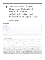
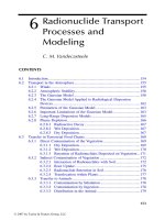
insulatingmaterialsinspeciclocations.Injectionmolding,averydifferentprocess
from lithography, is used to make everything from large appliance and electronics
enclosures to medical implants (Figure 3.1). For the latter, form is represented by the
controloftheimplantgeometry,andfunctionbythenecessarystrength,stiffness,
andwearpropertiesofthematerial.
3.1.2 LOOKING FORWARD…LOOKING BACK
Overthemanycenturiesofhumandevelopment,thefabricationofproductshas
changed enormously, in terms of materials, tools, scale, complexity, and degree of
human interaction. However, these changes have not been purely monotonic in their
progression.Forexample,earlymaterialswereall“naturalmaterials”—thatis,
wood from trees, skins from animals, stones from the ground. Although mixing of
materials to form metal alloys was conducted more than 4000 years ago, remarkable
advances have been made in materials processing within the most recent 50 years.
Included among these advances have been discoveries leading to new “man-made”
or synthetic developments, such as shape memory alloys that change shape at a
specied temperature, used for applications as varied as orthodontic wires, medical
insertion devices, and military actuators; polymer bers for ballistic protection or
moisture-wicking athletic clothing; and semiconductor materials that form the core
of all current electronic devices. More recently, however, there has been a return to
“natural materials” in efforts to create environmentally benign materials derived
from biodegradable and renewable resources.
FIGURE 3.1 Exampleofamicro-injectionmoldedmedicalimplant,nexttoapennyforscale.
(From Miniature Tool and Die, Charlton, MA, www.miniaturetool.com. With permission.)
© 2009 by Taylor & Francis Group, LLC
Overview of Manufacturing Processes 35
Inasimilarmanner,thelevelofskillandinteractionoftheworkerwiththeprod-
ucthasundergonecyclicchanges.PriortotheIndustrialRevolution,manufacturing
essentially consisted of individual hand work performed by skilled laborers. The
developmentofmassproductionintheearly1900sledtoariseinunskilledlabor,
as manufacturing equipment developments and scientic management taken to an
extremereducedtheworkertosimplyanothercomponentor“cog”intheassembly
line. The subdivision of labor to simple motions repeated over and over again was
promoted by Frederick Winslow Taylor [1]. Variations on the scientic management
themewithagreateremphasisonworkerwelfareandmassproductionofprod-
uctsaffordablebythegeneralpublicwerestudiedbyFrankandLillianGilbreth[1]
and Henry Ford, respectively. Worker conditions and the hazards of extreme indus-
trial efciency was a theme of Charlie Chaplin’s movie Modern Times (1936). With
new advances in automated equipment and computer control, however, the degree
ofrepetitiveassemblyandinspectionhasdecreased,andtherehasbeenashiftto
skilled(albeitnotinhandwork)workersfamiliarwithcomputersandanincreasein
theneedformoretechnicallyknowledgeableworkers.
Agrowingconcerninmorerecenttimesistheexposureofworkerstopoten-
tiallyhazardousenvironments—rangingfromtheobvioushazardsoflarge
mechanicalandelectricalequipment(e.g.,crushing,falls,electrocution),tothe
less visible dangers of exposure to chemicals and airborne particles (e.g., coal
dust). Improved safety protocols, safety lock-out systems and guards, and personal
protective equipment (e.g., gloves, masks, ventilation) have been developed to
addressworkenvironmenthazards.Nevertheless,withtheemergenceofeachnew
technology comes the potential for new, unknown hazards. Some hazards arise
fromthematerialsthemselves,asinthecaseofasbestosbersandlead.Others
arise from the manufacturing process, as in the increase of carpal tunnel and other
repetitivemotioninjuries.Tomitigatethepotentialharm,thescienticcommunity
must attempt to address potential hazards prior to or in parallel with new technol-
ogy development. One approach to doing so for manufacturing processes is to rst
identify what changes are anticipated in the manufacturing environment due to
the emerging technology, and then address any subsequent consequences. As was
illustrated previously, however, projecting forward is not simply a linear extension
ofobservationsofthepast.Forexample,itisunlikelythatpreventinginhalation
ofnanoparticleswillbesolvedsolelybycreatingmaskswithsmallerpores.Thus,
the next section provides a brief introduction to existing manufacturing processes,
followed in the ensuing section by a discussion of how these processes are likely
to change with the increased use of nanomaterials.
3.2 A BRIEFPRIMERONMANUFACTURINGPROCESSES
While there are many different major processes, each with many variations, manu-
facturingprocessescanbelooselygroupedintothefollowingvefamilies[2]:
© 2009 by Taylor & Francis Group, LLC
36 Nanotechnology and the Environment
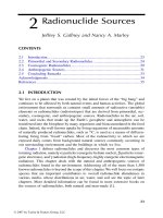
FIGURE 3.2 Examples of mass change — material removal manufacturing processes: (a)
laser machining and (b) waterjet cutting. ([a] From the Center for Lasers and Plasmas for
Advanced Manufacturing (CLPAM) website, www.engin.umich.edu/research/lamircuc; and
[b] from Flow International Corporation, Kent, WA, www.owcorp.com. With permission.)
© 2009 by Taylor & Francis Group, LLC
Overview of Manufacturing Processes 37
1. Mass change processes. These processes involve the addition or subtraction
ofmaterial.Themostobviousoftheseismachining,whichincludesmany
methods. In addition to standard mechanically based machine tools such
asdrills,lathes,millingmachines,andsaws,othertypesofenergyhave
been harnessed for material removal, including laser machining, water jet
cutting, and electrodischarge machining (EDM) (Figure 3.2). Additive pro-
ce
sses range from methods as old as electroplating, which involves using
anelectriccurrenttodepositametalcoatingontoaconductivesubstrate,to
newer approaches expanding on rapid prototyping methods such as ink-jet or
three-dimensional printing, selective laser sintering, and stereolithography.
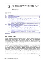
Therapidprototypingprocessescanbuildupcomplexthree-dimensional
shapes on a layer-by-layer basis (Figure 3.3), using advanced computer con
-
t
r
oltopreciselyplacepowdersandfuseorsinterthem,ortoselectivelycure
polymers in specied locations.
2. Phase change processes. The
se processes involve the shift of the material
fromonephasetoanother(e.g.,liquidtosolid,vaportosolid).Theinitial
phase provides ease of handling. For example, in injection molding, molten
polymerisabletoowintosmallchannelsandfeatures,andthensolidify
intoarigidpart.Similarly,incasting,moltenmetalcanbeforcedtoll
complex geometries. Less familiar perhaps are the vapor-to-solid processes
such as chemical vapor deposition (CVD) or physical vapor deposition
(PVD). In these processes, energy is used to transform the desired material
FIGURE 3.3 Exampleofacomplexthree-dimensionalgeometryfabricatedusingamass
change process — inkjet printing, an additive manufacturing process. (From Digital Design
Fabrication Group, MIT Department of Architecture, . With permission.)
© 2009 by Taylor & Francis Group, LLC
38 Nanotechnology and the Environment
into a vapor or plasma form, which is then deposited onto the substrate,
typicallyinathinlm.
3. (Micro-)structure change processes. M
o
stoftenusedtomodifyproper-
ties rather than geometry, structure change processes typically involve heat
treatment to remove residual stresses, increase ductility, and/or harden sur-
f
a
ces (e.g., precipitation hardening). The process can be used as an interme-
di
atestepincombinationwithotherprocessessuchasforgingtoenhance
the ability to create the desired geometry without fracturing the material.
A more recent variation on these processes is ion implantation, which is
used extensively in the semiconductor industry. The implantation of small
amounts of impurity atoms changes the chemical structure and thus the
electronicandphysicalpropertiesofthematerial.
4.
Deformation processes. The
se processes require some level of ductility
in the material. Constant cross-sections such as sheet, rod, tube, etc. can
be extruded through a die of the desired shape. Other geometries can be
createdbymatcheddiemolding,forging,thermostamping,etc.Inaddi
-
ti
ontocreatingthedesiredshape,theprocesscanbeusedtomodifythe
material, typically hardening the material with repeated impacts, such as in
forging.Formetals,manydeformationprocessesarecombinedwithstruc
-
tu
re change processes. The material is softened with heat (annealing) to
increaseitsductilitybothbeforedeformationandaftertoreduceresidual
stresses.
5.
Consolidation processes. Ty
picallyusedformaterialsthatarebrittleand
have high melting temperatures, consolidation processes are commonly
used for ceramics and high melt temperature metals. The materials are
initiallyinapowderform,whichisthencombinedwithaliquidtoproduce
aslurrythatowsintothemold.Pressureandheatarethenusedtocompact
the material and sinter the powders together to obtain strength.
Thechoiceofmanufacturingprocess,orinsomecasesthecreationofnewpro
-
c
e
sses, depends on a multitude of factors, including geometry, dimensional tolerance,
number of parts, and material. Examples of some common design decision-making
aspects are:
Geometry: complex vs. simple. Shapesrequiringconstantcross-sections
canbemadeincontinuousproduction,usuallybyforcingmaterialthrough
adieofthedesiredcross-section.Forexample,electricalwiresarecoated
with insulation by forcing the conductive copper wires through a slightly
larger circular hole in the presence of a molten polymer, which forms a thin
coating on the wire. Similarly, large aluminum I-beams, channels, pipes,
and rods are extruded in continuous production. Pulling instead of pushing
is necessary for ber-reinforced composites; hence the variation is pultru
-
si
on.Onestepupincomplexityisthefabricationofsimplebutnotcon-
st
ant cross-section geometries. These shapes can be formed easily using
•
© 2009 by Taylor & Francis Group, LLC
Overview of Manufacturing Processes 39
an automated version of the blacksmith’s craft of pounding horseshoes out
of rods of heated steel. At some point, however, forging, stamping, and
other mechanical deformation methods become too unwieldy a technique
to obtain highly complex, intricate shapes. Thus, processes that rely on uid
ow, such as casting and injection molding, are used to fabricate the many
intricatepartsinamodelcarkitorinamedicaldevice.Othertechniques
that rely on a “writing”-type, layer-by-layer process also provide increased
control for three-dimensional structures.
Dimensional tolerance and surface nish.T
he importance of the dimen-
sional precision and the surface nish affects the type of manufacturing
process selected. For example, vacuum forming, which uses a rigid tool
ononesideandaexiblesurfaceontheother,isamuchcheaper,lower
force,andmoreforgivingprocessthanformingwithapairofmatcheddie
molds,buttheproducedpartcanhavemuchgreaterthicknessvariations
and surface roughness. Products such as automotive body panels require
a“ClassA”surfacenishthatdisplaysnoscratches,dimples,wrinkles,
or other defects that would detract from the high-luster, polished appear
-
an
ce.Thesepanels,however,onlyrequiresuchanishononesideofthe
part—forexample,noonelooksattheundersideofthehood.Castparts
typicallyhavepoorsurfacenishanddimensionaltolerancebecauseof
the shrinkage and porosity that occurs as the molten metal cools. Polymers
also tend to shrink signicantly upon cooling; thus, many parts requiring
strictdimensionalcontrolutilizelledpolymers—thatis,polymersmixed
withshortchoppedbersorotherllers—toreduceshrinkage,moisture
absorption, and creep.
Number of parts.T
he anticipated volume of parts and desire for exibility
indesignplayanimportantroleinprocessselection.Expensivetooling,
costingontheorderoftensofthousandsofdollarsandup,isonlypractical
ifthecostcanbespreadovermanyparts.Incontrast,customizableprod-
uct
s must rely on easily modied processes such as machining and rapid
prototyping. Another example can be found within the many variations on
thecastingprocess—sandcasting,lostwaxorinvestmentcasting,diecast-
in
g,centrifugalcasting,etc.Thersttwovariationsinvolvedestroyingthe
moldforeachpart,whereasthelattertwovariationsutilizereusablemolds.
Reusable molds are fabricated from much more expensive materials and
only become economical for the production of a large number of parts (or
fewerbutmoreexpensiveparts).
Material. In the eld of materials engineering, a common description of
the interrelation of multiple factors is the structure-property-processing tri-
an
gle(Figure3.4).Thedesignowdoesnothaveasinglestartingpoint,as
each node affects the other two. For example, the rate at which a polymer is
extruded and cools affects its crystallinity (structure), which then affects its
stiffnessandstrength(property).Amaterialthatisbrittle(property)would
notbesuitableforforging(processing).
•
•
•
© 2009 by Taylor & Francis Group, LLC
40 Nanotechnology and the Environment
3.3 RAMIFICATIONS OF WORKER EXPOSURE AND
ENVIRONMENTAL ISSUES FOR NANOMANUFACTURING
In considering the progression of manufacturing processes with respect to the work
environment, there has been a general trend over the past hundred years toward
improvedsafety,withsignicantadvancesmadeinthemajorindustries.Therate
ofchange,however,canvarybyindustry.Industrieswithalonghistoryandlarge,
expensive capital equipment naturally tend to move more slowly than newer indus-
tr
iesthatgerminatedwithcomputerized,automatedequipment.Forexample,much
of the forging, casting, and sheet metal industry is still represented by workplaces
that are loud, hot, and particulate-laden. In contrast, the biotechnology industry
relies on clean, well-controlled environments, where the risk is more of the unseen,
in both process and waste streams. Because nanotechnology and nanomaterials are
anticipatedtoaffectbothoftheseindustriesandmanymore,thequestionarisesas
tohowthemanufacturingenvironmentwillchange.Howwillissuesofworkerexpo
-
s
u
re and environmental impact differ for nanomaterials?
3.3.1 FOUR “GENERATIONS” OF NANO-PRODUCT DEVELOPMENT
Inthecaseoftheincorporationofnanomaterialsintoproducts,severalgenerations
ofchangestomanufacturingcanbeanticipated.Currentproductsinthemarketplace
todaytypicallyfallintothe“1stgeneration,”whererelativelyminormodications
to existing processing equipment were needed to incorporate nanomaterials into the
product. For example, surface coatings of nanobers and nanowhiskers have been
usedforimprovedltrationandforthe“nano-pants”fabricmadebyNano-Tex[3].
M
ore than 20 years ago, Toyota incorporated clay nanoparticles into polymer resins
to create automotive body panels with improved strength, toughness, and dimen-
si
onalstability[4].Thesetypesofnanocompositeproductsarestillfabricatedusing
conventional injection molding, extrusion, and cast lm processes, but additional
compounding steps or other modications to the processes were made to create a
Processing
Structure
Propert
y
FIGURE 3.4 Structure-Property-Processing interrelationship for materials.
© 2009 by Taylor & Francis Group, LLC
Overview of Manufacturing Processes 41
well-dispersed nanoller [5]. As greater understanding is achieved, more advanced
processes and products are developed.
The following generational designations have been described on several occa-
sionsbyM.C.Roco,whoisrecognizedasoneofthekeyarchitectsoftheNational
Nanotechnology Initiative (NNI). A more detailed presentation can be found in a
chapterbyRocoreviewingthehistoryoftheNNI,itsevolutionoverthepastdecade,
and the future prospects for this technology and its impact on society [6]. Additional
information emphasizing aspects related to manufacturing at the nanoscale appears
in a report issued by the National Nanotechnology Coordination Ofce
[7].
The “1st generation” products (2000+): represented primarily by passive
nanostructures. The
majority of products that are already commercial-
ized fall into this category, where the nanoscale element (e.g., nanoparticle,
nanoclay platelet, nanotube) is incorporated into a matrix material for coat-
ings, lms, and composites, or is part of a bulk nanostructured material.
The processes for fabricating the target nanomaterials discussed in this
book, as well as the products incorporating these nanoparticles represent
therstgenerationofnanoproducts.
The “2nd generation” products (2005+): represented by active nanostruc-
tures. In these structures, the nanoscale element is the functional struc-
ture, as in the case of nanospheres and nanostructured materials for drug
delivery.Thematerialsarefunctionalinthattheyrespondtosomeexternal
stimulisuchaspHortemperaturetoreleasethestoreddrugatacontrolled
rate. Other examples include sensors and actuators, transistors, and other
electronics,whereindividualnanowiresservetoprovidetheswitchingor
amplifying mechanism.
The “3rd generation” products (2010+): represented by three-dimensional
nanosystems and multi-scale architectures, expanding beyond the two-
dimensional layer-by-layer approach currently used in microelectronics.
Thesesystemswillbemanufacturedusingvariousdirectedself-assembly
methodssuchasbio-assembly(e.g.,usingDNAandvirusesastemplates),
electrical and chemical template-guided assembly.
The “4th generation” products (2015+): represented by truly heteroge-
neous molecular nanosystems. In these products, multi-functionality and
controloffunctionwillbeachievedatthemolecularlevel.
Common to all four generations of product development are three stages where
exposuretonanomaterialsisthemostsignicant.Ingeneral,nanomaterialssuch
as carbon nanotubes and silver
nanoparticles can be relatively expensive, so com-
panieswillwanttoreducewasteasmuchaspossible.Nevertheless,exposureand
entryintothewastestreamcanoccur:(1)duringfabricationofthenanomaterial;(2)
during storage and handling of the nanomaterial, including during incorporation of
thenanomaterialintoanothermaterial,structure,ordevice;and(3)duringmate-
rialremovalorfailureuponfurtherprocessingordisposaloftheproduct.Oncethe
nanomaterialisincorporatedintoabulkmaterial(e.g.,acarbonnanotubebonded
within a polymer matrix), the concern is the same as that for the bulk material and
•
•
•
•
© 2009 by Taylor & Francis Group, LLC
42 Nanotechnology and the Environment
isnotrelatedtothenanoscaledimensionsorproperties.Priortoembedmentorin
thecaseofreleaseatendoflifedisposal,theuniquepropertiesofnanomaterials
do have a very different effect. The most obvious case is that of worker exposure.
Withparticlesroughly1/1000ththediameterofchoppedglassbers,theconcernis
that ltration and ventilation regulations are not effective. The behavior also is not
monotonicwithsize.Somepropertiesmayactuallymakeiteasiertolterorcollect
any stray nanomaterials. For example, the Brownian motion of nanoparticles results
inamoretortuoustravelpaththatmaymakecaptureeasier.Similarly,thehighreac
-
ti
vity of the surface-dominated particles can lead to a greater ease of collection; for
example, nanoparticles tend to agglomerate into much larger clusters, making them
easier to detect and lter.
3.3.2 THE IMPACT OF “ENGINEERED” NANOMATERIALS
More than 10 years ago, as capabilities of measuring particles below 100 nano-
meters (nm) were developed, signicant research focused on “ultrane” particles
resulting from vehicle emissions and combustion-related manufacturing processes
such as welding. Since that initial research into nanoparticles as byproducts, inter
-
est in engineered nanoparticles has grown. The breadth of processes creating and
utilizing nanoscale materials raises more challenges. Engineered nanomaterials are
beingcreatedviamultiplemethods,forexample,arcdischarge,laserablation,CVD,
gas-phase synthesis, sol-gel synthesis, and high-energy ball milling. These processes
can begin from the “bottom up,” assembling nanomaterials from their components,
for example by chemical synthesis or phase change processes. Other manufacturing
methods begin with bulk materials, reducing their size via mass change processes to
create nanomaterials from the “top down.”
Thebottom-upsynthesisroutesare,byfar,themostwidelyusedfornanoparti
-
cles. While engineered nanoparticles often are thought of as precursors or raw mate-
ri
alstobeincorporatedintohighervalue-addedproductsviaoneofthevefamilies
of processes described previously in this chapter, the initial step of synthesizing
nanoparticles most closely ts within the family of “phase change processes,” which
includes processes such as CVD. The use of top-down methods such as high-energy
ball milling is limited to larger diameter particles with less stringent monodispersity
and purity requirements. Ball milling is essentially a grinding process that would t
within the machining processes of the “mass change processes.”
As with the other manufacturing processes, the process-structure-property inter
-
re
lationshipsaresignicant.Forexample,themanufacturingprocesscanaffectthe
atomicstructureofcarbonnanotubes,whichinturnaffectsmanyproperties,suchas
the electrical conductivity (e.g., metallic vs. semiconducting), thermal conductivity,
strength, and stiffness. One relatively coarse difference is the production of single-
walled nanotubes (SWNTs) versus multi-walled nanotubes (MWNTs). Single-walled
nanotubes have better conductivity and strength properties but are much less reactive
and therefore more difcult to functionalize (i.e., to create compatibility with other
materials for bonding). In general, the properties of nanoparticles are governed by
process-inducedfactorssuchasthesizeandsizedistribution,degreeofporosity,
and surface reactivity. In synthesis processes, size and structure can be controlled
© 2009 by Taylor & Francis Group, LLC
Overview of Manufacturing Processes 43
through the use of catalyst particles, template materials (e.g., to control nucleation
and precipitation behavior), and controlled-size droplets or aerosols.
Thesixnanomaterialsthatarethefocusofthisbook—carbonblack,carbon
nanotubes, fullerenes (also known as C60 or buckyballs), nano silver, nano titanium
dioxide,andnanozero-valentiron—canallbefabricatedusingmanymethods,
and with the interest in nanomaterials, new methods are being discovered rapidly. A
quicksearchintheU.S.PatentandTrademarkOfcedatabase[8]bringsuproughly
50 patents issued in the past two years with “nanoparticle” in the title. These patents
include methods of making nanoparticles, modifying nanoparticles, and products
incorporating nanoparticles. Table 3.1 provides a few examples of manufacturing
techniquesforthesixtargetmaterials.
3.3.3 INTEGRATING NANOPARTICLES INTO NANOPRODUCTS
In some processes, the synthesis of the nanoparticle and subsequent deposition onto
a substrate occurs in one continuous process. In others, however, the nanomaterial
must be collected and stored until needed for later processing. Some earlier nanopar
-
ti
cle synthesis approaches resulted in the nanomaterial adhering to the walls of the
reactor, requiring physical removal equivalent to “scraping the soot from the walls.”
Needless to say, such direct contact with the materials leads to worker exposure
issues. Newer methods emphasize limiting human contact with the nanoparticles,
partially for worker safety, but also for economic reasons: reducing contamination
and increasing yield.
Once the nanomaterial is manufactured and sold as a raw material to multiple
customers, the next stage of exposure is handling during incorporation into a prod
-
uct
.Dispersionisoftenthekeyprocessinincorporatingnanomaterialsintobulk
materials.Thisofteninvolvessomechemicalmodicationofthesurfacetocause
the nanomaterials to be less likely to agglomerate with each other and more likely to
bondtothebulkmaterial.Again,onceinasolventorsuspensionormelt,thenano
-
mat
erials are very unlikely to be inhaled, but dermal contact may still be a concern.
Thus,thestepofintroducingthenanoparticlesornanotubesintothesolutionormelt
isthepotentialhazardpoint.Beyondthispoint,thematerialremainsinaclosed
environment(e.g.,inameltbeingmixedinatwin-screwextruder).
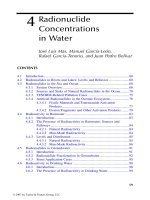
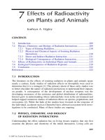
For future generations of products, the vision is that of three-dimensional multi-
material, directed self-assembly manufacturing processes. Simple two-dimensional
examples include the organization of nanoparticles and other nanomaterials using
conductive vs. nonconductive patterns (Figure 3.5) and the alignment of nanotubes
innarrowtrenches.Indirectedassembly,thematerialtobeassembled(e.g.,con
-
du
ctive polymer, nanoparticles, nanotubes) is exposed to the template. Then, with
thehelpofsomedrivingforcesuchasanelectriceld,magneticeld,orchemical
attraction, the nanomaterials assemble into a desired pattern over a large area within
a short time. The benet of these directed assembly processes is that the amount of
handling will further decrease and the raw material is often in solution (e.g., not sub
-
ject to inhalation). This is an advantage not only for repeatability, but also for worker
exposure. The environmental question that then arises is the capture and reuse of
© 2009 by Taylor & Francis Group, LLC
44 Nanotechnology and the Environment
TABLE 3.1
Examples of Manufacturing Methods for Target Nanomaterials
Nanomaterial Process Description Ref.
Titanium dioxide Minerals rutile (TiO
2
) and ilmenite (FeTiO
3
) are extracted from heavy
mineral sands. Nanoscale particles can be manufactured by milling,
but ner TiO
2
particles can be manufactured by a combination of
chemical synthesis and milling:
Prepare aqueous solution of TiCl
4
in solution with HCl, HPO
4
.
Vacuum-dry solution and spray-dry at 200–250°C to produce dry
TiO
2
.
Calcinate at 600–900°C for 0.5–8 hours to produce crystalline
nanostructure.
Wash precipitate with C
2
H
5
OH, dry, and mill to nano-sized
particles.
[9–11]
Zero-valent iron The following processes are currently used in commercial production
to manufacture nano zero-valent iron:
React ferric chloride with sodium borohydride to create particles
approximately 50 nm in diameter.
React iron oxides (goethite and hematite) with hydrogen at 200–
600°C to form particles approximately 70 nm in diameter
containing Fe
0
and Fe
3
O
4
.
[12–14]
Silver Silver is recovered from ore via smelting and electrolysis. Nanoscale
particles can be created by several processes:
Silver powder can be generated by atomizing molten silver (e.g.,
via a high-velocity gas jet) to create very small droplets that then
solidify into powder form.
Very ne silver particles are more commonly produced by
chemical precipitation, e.g., from silver nitrate using a reducing
agent (e.g., ascorbic
acid).
In a new variation on this process, the
reaction occurs in a spinning disk processor (SDP); nanoparticles
5–200 nm form in a thin uid lm on the rotating disk surface.
Nanometer-sized angular silver particles (1–100 nm) are produced
when a high-power laser beam strikes a metallic block of silver
immersed in a silver salt solution.
Electrolysis of a silver electrode in deionized water produces
colloidal silver containing both metallic silver particles (1–25
wt%) and silver ions (75–99 wt%).
[15–17]
© 2009 by Taylor & Francis Group, LLC
Overview of Manufacturing Processes 45
excesssolutionandnanomaterial;thiscan,inaveryroughsense,beconsidered
similartotheproblemofcollectionofcuttinguidsinmachining.
With respect to separation of the nanomaterial during further processing or dis-
posal,animportantquestionisthestrengthofthebonding.Thatis,howeasilywill
thenanomaterialsseparatefromasubstrateandthenpotentiallybefreedintothe
environment?Atthenanoscale,secondarybondsfromvanderWaalsforcesplaya
signicant role. These bonds are, however, not as strong as chemical bonds (physi-
sorption vs. chemisorption), although there are strong physisorption and weak chemi-
sorption conditions that approach a middle ground. As with the current issues facing
recyclingofmulti-materialsystems,theipsidetoundesirednanomaterialliberation
is the desire to easily separate materials for reuse upon disposal of the product.
TABLE 3.1 (CONTINUED)
Examples of Manufacturing Methods for Target Nanomaterials
Nanomaterial Process Description Ref.
Carbon black Carbon black is produced from the incomplete combustion or thermal
decomposition of hydrocarbons under controlled conditions. As the
combustion products collide in the reactor, they form ever-larger
particles by aggregation and agglomeration. Two methods produce
most of the commercial carbon black: oil furnace and thermal black.
The oil furnace process produces more than 95% of commercial
carbon black. Preheated oil is atomized and partially combusted in a
heated gas stream. The gas stream is quenched with water and carbon
black is recovered on a bag lter. Recovered carbon black is mixed
with water, then air-dried.
The thermal black process, which entails the thermal decomposition of
natural gas, accounts for most of the remaining production of carbon
black.
[18, 19]
Carbon
nanotubes
HiPco process of gas-phase chemical-vapor-deposition is currently in
commercial use to manufacture single-walled carbon nanotubes
(SWNTs):
Introduce Fe(CO)
5
catalyst into injector ow via pressurized CO.
Heat catalyst stream and mix with CO in graphite heater. Fe(CO)
5
decomposes to Fe clusters. Standard running conditions: 450 psi
CO pressure, 1050°C.
C atoms coat and dissolve around the Fe clusters, forming
nanotubes. Running conditions maintained 24–72 hours.
Gas ow carries SWNTs and Fe particles out of the reactor.
SWNTs condense on lters. CO passes through NaOH absorbtion
beds to remove CO
2
and H
2
O, then is recycled.
[10, 11]
Fullerenes (C60
or buckyballs)
Fullerenes can be manufactured by several processes:
Fires and lightning strikes naturally generate small amounts of
fullerenes.
Production in laminar benzene-oxygen-argon ame. Carbon arc
discharged from graphite electrodes (Krätschmer-Huffman
method).
[10, 11,
20]
© 2009 by Taylor & Francis Group, LLC
46 Nanotechnology and the Environment
FIGURE 3.5 Example of template-directed assembly of a conductive polymer (doped poly-
aniline,PANi)using100-nmgoldlinesonasiliconwafer(assemblyvoltageandtimeis
indicatedoneachimage).(FromProfessorJoeyMead,Dr.MingWei,andMr.JiaShen,Uni-
versityofMassachusetts–Lowell,www.uml.edu/nano.Withpermission.)
© 2009 by Taylor & Francis Group, LLC
Overview of Manufacturing Processes 47
3.4 SUMMARY
Understanding the environmental implications of any new technology is crucial to
long-term sustainability. Unfortunately, such problems are complex, with many dif-
fe
rentpointsalongthelifecycleoffabrication,handlingandintegration,anddis-
po
salthatmustbeaddressed.Evenwithinjustonemainprocesscategory,suchas
handlingandintegrationofnanomaterialsintonanoproducts,thebreadthofdifferent
manufacturingprocessesandmaterialsisvast,encompassinggas,liquid,andsolid
phases, as well as chemical, electrical, and mechanical deformation and assembly
mechanisms. An all-inclusive answer to ensuring environmental safety and sustain
-
ab
ility is not viable, but the remainder of this book addresses some of the existing
nanomaterials that have shown relatively high volume commercial applicability. By
understanding more about current nanomaterials and nanomanufacturing processes,
the transfer of knowledge to yet-to-be-developed nanomaterials and processes will
be invaluable.
REFERENCES
1. Nelson,D.1980.Frederick W. Taylor and the Rise of Scientic Management. Madison,
WI: The University of Wisconsin Press.
2. National Research Council. 1995. Unit Manufacturing Processes: Issues and Opportu-
nities in Research. W
ashington, D.C.: National Academy Press.
3. NanoTex®.
. (Accessed November 30, 2007)
4. Okada,A.andA.Usuki.2006.Twentyyearsofpolymer-claynanocomposites.Macro-
molec, Mater. Eng., 2
91(12):1449–1476.
5.Sherman,L.1999.Nanocomposites:alittlegoesalongway.Plastics Technol.,
45(6):52.
6. R
oco,M.C.2007.NationalNanotechnologyInitiative—Past,Present,andFuture.
In Handbook of Nanoscience, Engineering, and Technology,2n
d edition. Eds. W.A.
GoddardIII,D.W.Brenner,S.E.Lyshevski,andG.J.Iafrate.BocaRaton,FL:Taylor&
Francis.
7.
National Science and Technology Council, Subcommittee on Nanoscale Science,
Engineering, and Technology. 2007. Manufacturing at the Nanoscale: Report of the
National Nanotechnology Initiative Workshops, 2002–2004.E
ds. J. Chen, H. Dou-
manidis, K. Lyons, J. Murday, and M.C. Roco. Washington: National Nanotechnology
Coordination Ofce.
8. U.S. Patent and Trademark Ofce. (Accessed November 30,
2007)
9.
Fisher, J. and T.A. Egerton. 2001. Titanium Compounds, Inorganic. In Kirk-Othmer
Encyclopedia of Chemical Technology.
NewYork:JohnWiley&Sons,Inc.
10. Robichaud, C.O., D. Tanzil, U. Weilenmann, and M.R. Wiesner. 2005. Relative risk
analysis of several manufactured nanomaterials: an insurance industry context. Envi-
ron. Sci. Technol., 3
9(October):8985–8994.
11. Robichaud, C.O., D. Tanzil, U. Weilenmann, and M.R. Wiesner. 2005. Supporting
information for relative risk analysis of several manufactured nanomaterials: an insur-
an
ce industry context. Environ. Sci. Technol., Published online October 4, 2005. http://
pubs.acs.org/subscribe/journals/esthag/suppinfo/es0506509/es0506509si20050812_
025756.pdf. (Accessed July 4, 2007)
© 2009 by Taylor & Francis Group, LLC
48 Nanotechnology and the Environment
12. Zhang, W.X. 2005. Nano-Scale Iron Particles: Synthesis, Characterization, and Appli-
ca
tions. Meeting Summary:
U.S. EPA Workshop on Nanotechnology for Site Remedia-
tion. Washington, D.C. 20–21 October. />13. Vance, D. 2005. Evaluation of the control of reactivity and longevity of nano-scale col
-
l
o
idsbythemethodofcolloidmanufacture
. Meeting Summary: U.S. EPA Workshop on
Nanotechnology for Site Remediation. Washington, D.C. 20–21 October. r.
gov/nano.
14
. Wiesner,M.R.,G.V.Lowry,P.Alvarez,D.Dionysiou,andP.Biswas.2006.Assessing
the risks of manufactured nanomaterials.
Environ . Sci. Technol., 40(14):4336–4345.
15. Etris, A.F. 2001. Silver and silver alloys. In
Kirk-Othmer Encyclopedia of Chemical
Technology, 4:761–803.NewYork:JohnWiley&Sons,Inc.
16.Key,F.S.andG.Maas.2001.Ions,AtomsandChargedParticles.ver-
colloids.com/papers/IonsAtoms&ChargedParticles. (Accessed October 6, 2007)
17.Iyer,K.S.,C.L.Raston,andM.Saunders.2007.Transformingnano-sciencetonano-
technology: manipulating the size, shape, surface morphology, agglomeration, phases
and defects of silver nano-particles under continuous ow conditions.
NSTI-Nanotech
2007, p. 4.
18. Wang, M J., C.A. Gray, S.A. Resnek, K. Mahmud, and Y. Kutsovsky. 2003. Carbon
black. In
Kirk-Othmer Encyclopedia of Chemical Technology 4:761–803. New York:
John Wiley & Sons, Inc.
19. International Carbon Black Association. 2004. Carbon Black User’s Guide. http://car
-
bon-black.org. (Accessed August 30, 2007)
20. Holister,P.,C.RomanVas,andT.Harper.2003.Fullerenes:TechnologyWhitePapers
nr. 7. Cientica, Ltd. (October). ntica.com.