Solar Cells Dye Sensitized Devices Part 12 docx
Bạn đang xem bản rút gọn của tài liệu. Xem và tải ngay bản đầy đủ của tài liệu tại đây (4.46 MB, 30 trang )
Solar Cells – Dye-Sensitized Devices
322
nanoparticle aggregates and the rapid electron transport rate and the light scattering effect
of single-crystalline nanowires (Tan et al., 2006). An enhancement of power efficiency from
6.7% for pure nanoparticle cells to 8.6% for the composite cell with 20 wt% nanowires was
achieved, showing that employing nanoparticle/nanowire composites represented a
promising approach for further improving the efficiencies of DSCs. C. H. Ku et al. reported
ZnO nanowire/nanoparticle composite photoanodes with different nanoparticle-occupying
extents (Ku et al., 2008). Aligned ZnO nanowires were grown on the seeded FTO substrate
using an aqueous chemical bath deposition (CBD) first, and then, growth of nanoparticles
among ZnO NWs by another base-free CBD was preceded further for different periods. The
corresponding DSCs showed an efficiency of 2.37%, indicating the good potential of the
hybrid nanostructures in ordered photoanodes.
Apart from the direct blending of two different semiconductor components as mentioned
above, the coating technique has also been applied widely to create the hybrid photoanodes.
M. Law et al. developed photoanodes constructed by ZnO nanowires arrays coated with
thin shells of amorphous Al
2
O
3
or anatase TiO
2
by atomic layer deposition (Law et al., 2006).
They found that, while alumina shells of all thicknesses acted as insulating barriers that
improve cell open-circuit voltage only at the expense of a larger decrease in short-circuit
current density, titania shells in thickness of 10-25 nm can cause a dramatic increase in V
OC
and fill factor with little current falloff, resulting in a substantial improvement in overall
conversion efficiency (2.25%). They attributed the improved performance to the radial
surface field within each nanowire that decreases the rate of recombination. K. Park et al.
described a ZnO-TiO
2
hybrid photoanode by coating ultrathin TiO
2
layer by atomic layer
deposition on submicrometer-sized aggregates of ZnO nanocrystallites (Park et al., 2010).
The introduction of the TiO
2
ultrathin layer increased both the open circuit voltage and the
fill factor as a result of the suppressed surface charge recombination without impairing the
photocurrent density, thus realizing more than 20% enhancement in the conversion
efficiency from 5.2% to 6.3%. S. H. Kang et al. examined effects of ZnO coating on the anodic
TiO
2
nanotube array film on the conversion efficiency (Kang et al., 2007). Compared with
the solid-sate cells consisted of an anodic TiO
2
film as the working electrode under backside
illumination, an almost 20% improvement from the ZnO coating was achieved (from 0.578%
to 0.704%), which can be attributed to the suppressed electron flow to the back-direction and
the enhanced open-circuit voltage.
Despite considerable effects in this area, however, the record efficiency of 11% for DSCs is
not surpassed by these new type cells, due to the complexity of both the nanoporous
photoanode and the cell structure of DSCs. Much comprehensive and in-depth work related
to this topic is required.
In this chapter, we focused on the ordered photoanode film built up by two semiconductor
materials, zinc oxide (ZnO) and titanium oxide (TiO
2
). Three type of ZnO nanostructures
were selected, including the nanowire array (grown by the hydrothermal method), the
nanoporous disk array grown on FTO substrate, and the nanoporous disk powder
(transformed from the solution-synthesized zinc-based compound ZnCl
2
.[Zn(OH)
2
]
4
.H
2
O).
Different types of TiO
2
nanoparticles were used, including commercial nanoparticles P25 &
P90 (Degauss Co., Germany), and home-made hydrothermal TiO
2
nanoparticles, which have
been widely used in producing traditional high-efficiency DSCs. Two kinds of preparation
technique of ZnO-TiO
2
hybrid film were used according to the status of ZnO nanostructures
(array or powder). The microstructure, optical and electrical properties of the hybrid film
were investigated, and the performance of corresponding DSCs was measured and
Ordered Semiconductor Photoanode Films for
Dye-Sensitized Solar Cells Based on Zinc Oxide-Titanium Oxide Hybrid Nanostructures
323
compared with results of traditional cell. In special, the emphasis was placed on the
controlling method of the microstructure of ZnO-TiO
2
hybrid films, and on the electron
transporting mechanism in the hybrid films.
2. ZnO nanowire array/TiO
2
NPs hybrid photoanodes
In this section, two types of ZnO nanowire (NW) array were selected, i.e., dense and sparse
NW array, with an aim to examine the effects of the distribution density of NW on the
microstructure and photoelectrochemical properties of the hybrid cells. For the dense NW
array, the ultrasonic irradition was used to promote the penetration of TiO
2
nanoparticles in
the interstice of ZnO NWs.
2.1 Hybrid photoanodes based on dense ZnO NW array
ZnO nanowire (NW) arrays were grown on ZnO-seeded fluorinated tin oxide (FTO, 20 Ω/□)
substrates by chemical bath deposition method. ZnO seed layer was prepared by sol–gel
technique. ZnO NW arrays were obtained by immersing the seeded substrates upside-down
in an aqueous solution of 0.025 mol/L zinc nitrate hydrate and 0.025 mol/L
hexamethylenetetramine (HMT) in a sealed beaker at 90 °C for 12 h. After the deposition of
ZnO NW, TiO
2
nanoparticles (NPs) were coated on ZnO NW by dipping the substrate into a
well-dispersed TiO
2
suspension containing 0.5 g TiO
2
NPs (P25), 20 μL acetyl acetone, 100
μL Triton X-100 in 10 mL distilled water and 10 mL ethanol with 20 μL acetic acid. To
facilitate the attachment and the gap filling of TiO
2
NPs into the interstices of ZnO NWs, the
ultrasonic irradiation generated from a high-density ultrasonic probe (Zhi-sun, JYD-250, Ti
alloy-horn, 20–25 kHz) was applied to TiO
2
suspension. The working mode was adjusted to
work for 2 seconds and idle for 2 seconds, with the repetition of 99 cycles. The electrodes
were then withdrawn at a speed of 3 cm per minute, dried, and sintered at 450 °C for 30 min
in air. Figure 2 gave the schematic for the fabrication of the hybrid ZnO NW array/TiO
2
photoanopde.
For DSCs fabrication, ZnO NW based electrodes were immersed in a 0.5 mmol/L ethanol
solution of N719 for 1 h for dye loading. The sensitized electrode was sandwiched with
platinum coated FTO counter electrode separated by a hot–melt spacer (100 μm in thickness,
Dupont, Surlyn 1702). The internal space of the cell was filled with an electrolyte containing
0.5 mol/L LiI, 0.05 mol/L I
2
, 0.5mo/L 4-tertbutylpyridine, and 0.6 mol/L 1-hexyl-3-
methylimidazolium iodide in 3-methoxypropionitrile solvent. The active cell area was
typically 0.25 cm
2
.
Fig. 2. Schematic of the preparation process of ZnO NW array/TiO
2
nanoparticles hybrid
photoanode. NW: Nanowire.
Solar Cells – Dye-Sensitized Devices
324
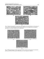
Fig. 3. FESEM images of ZnO NW arrays (a)–(b), hybrid ZnO NW/TiO
2
NP photoanodes
prepared without (c)–(d), and with (e)–(f) the ultrasonic treatment. (g) Low and (f) high-
resolution TEM images of the hybrid photoanodes prepared with ultrasonic treatment.
(Reproduced from Ref. (Gan et al., 2007))
Figure 3 showed the top and side-view SEM images of ZnO NWs grown on FTO substrate
and ZnO-TiO
2
hybrid photoanode film with/without ultrasonic treatment. Results indicate
that, for ZnO nanowire array with a density of ∼3.3×10
9
cm
−2
and an average diameter of 80
nm and length of 3 μm, TiO
2
slurry with relatively high viscosity is difficult to penetreate
into the inner pore of ZnO nanowires. As can be seen from Fig.3 c and d, only a small
Ordered Semiconductor Photoanode Films for
Dye-Sensitized Solar Cells Based on Zinc Oxide-Titanium Oxide Hybrid Nanostructures
325
amount of TiO
2
NPs were covered on the side surface of NWs and most of the NPs sit on the
top of NWs without filling in the inner gaps. When the ultrasonic irradiation was applied,
the coverage of NPs on the side surface of NWs was significantly improved (Fig. 3 e-h), and
TiO
2
NPs were uniformly infiltrated into the interstices of NWs rather than stuck to the top
of NWs. The cavitation in liquid–solid systems induced by the ultrasonic irradiation bears
intensive physical effects, which can promote the transfer of TiO
2
NPs and drive them
infiltrating into the gaps of NPs.
Figure 4 (left) showed the absorption spectra of the N719-sensitized ZnO NW, and hybrid
ZnO NW/TiO
2
NP electrodes prepared with and without ultrasonic treatment, respectively.
The absorption peak at around 515 nm, which corresponded to metal to ligand charge
transfer (MLCT) in N719 dye (Nazeeruddin et al., 1993), significantly increased for the
hybrid electrodes as compared to that of the pure ZnO NW electrode, proving that the dye-
loading content is apparently increased upon the combination of ZnO NW with TiO
2
NPs.
Besides, the hybrid electrode prepared with ultrasonic treatment showed an increase in the
absorption in the wavelength range of 400–800 nm compared with that without ultrasonic
treatment, indicating the higher surface area and the enriched light harvesting property by
filling more TiO
2
NPs into the interstices between ZnO NWs with the assistance of
ultrasonic irradiation.
Figure 4 (right) illustrated I–V characteristics of DSCs based on pure ZnO NWs and ZnO/TiO
2
hybrid photoanodes. Results show that the short-circuit current density (I
sc
) and the
conversion efficiency (η) of ZnO NWs based cell can be dramatically improved by
incorporating TiO
2
NPs, which can be ascribed to the increase in the surface area and the dye
loading quantity. However, the open-circuit voltage (V
oc
) and the fill-factor (FF) of the hybrid
DSCs decreased compared to those of pure ZnO NW DSC, which may be resulted from the
increased interfaces and surface traps in the hybrid photoanode which may act as the
recombination center under illumination. For the hybrid photoanode prepared with ultrasonic
treatment, its I
sc
, V
oc
, FF, and η was 3.54 mA/cm
2
, 0.60 V, 0.37, and 0.79%, respectively,
indicating an approximately 35% improvement of the overall conversion efficiency compared
with the photoanode without ultrasonic treatment. This improvement may originate from the
enhanced light harvesting and the better attachment of TiO
2
NPs to ZnO NWs resulted from
the efficient pore filling induced by the ultrasonic irradiation treatment.
Fig. 4. The absorption spectra (left) of N719-sensitized ZnO NW arrays, and hybrid ZnO
NW/TiO
2
NP photoanodes prepared without and with ultrasonic treatment, and I–V
characteristics of corresponding DSCs (right). (Reproduced from Ref. (Gan et al., 2007))
Solar Cells – Dye-Sensitized Devices
326
In summary, these results indicate that, for the hybrid films combining dense ZnO NW
array and TiO
2
NPs, the crucial aspect is to make TiO
2
NPs contained in the slurry penetrate
into the deep interstice of ZnO NWs. The application of ultrasonic irradiation or other
external fields may be helpful for the penetration of TiO
2
NPs, which usually result in the
increase of the photoelectrochemical performance of the hybrid cells. However, it seems that
the full filling of TiO
2
in the dense NW array is very difficult based on the current technique.
So it is meaningful to develop the sparse nanowire array or other forms of TiO
2
NPs, to
realize the good combination of ZnO NW array and TiO
2
NPs.
2.2 Hybrid photoanodes based on sparse ZnO NW array
In this section, ZnO NW array with sparse density was integrated with TiO
2
NPs, to form
the hybrid photoanode. The growth of sparse ZnO NW array was realized by reducing the
pH value of the precursor via the chemical bath deposition (CBD) method. The substrates
and the experimental parameters were similar to those of dense one except the
concentration of Zn
2+
and HMT (both 0.02 mol/L), and the pH value (2.0-3.0).
TiO
2
slurry was prepared following the method in Ref (Ito et al., 2008), and the mass ratio
of TiO
2
, ethyl cellulose, and terpineol was 18 : 9 : 73. Due to the acid-dissolute nature
of ZnO materials, the pH value of TiO
2
slurry should be controlled neutral or weak
alkaline.
The preparation of the hybrid film based on sparse ZnO NW array was similar to that of
dense array, as described in Section 2.1. The sensitization of the film was carried out in N719
dye solution dissolved in a mixture of acetonitrile and tertbutyl alcohol (volume ratio, 1:1)
for 20-24 hours at room temperature. The fabrication of the cells was similar to the
procedure described in Section 2.1, with the electrolyte composition of 0.6 M BMII, 0.03 M I
2
,
0.10 M guanidinium thiocyanate and 0.5 M 4-tertbutylpyridine in a mixture of acetonitrile
and valeronitrile (volume ratio, 85:15).
Figure 5 gave SEM images of sparse ZnO NW on the surface and cross section. It can be seen
that the density of ZnO nanowire on FTO substrate is much sparser than the dense ZnO NW
(Figure 3 a&b). But with the decrease of the density, the diameter of ZnO NW increases
greatly, up to several micrometers.
The hybrid cell based on the sparse ZnO NW array exhibited the conversion efficiency of
2.16%, lower than the TiO
2
NPs-based cell (2.54%) as illustrated in Figure 6. The decreased
efficiency of the hybrid cell is mainly resulted from the reduced photocurrent density
compared with the TiO
2
cell, while the open voltage keeps unchanged and the fill factor
improved from 0.06 to 0.078. The open-circuit voltage decay (OCVD) analysis (Figure 6)
indicated that the hybrid film exhibits longer decay time when the illumination is turned off,
indicating lower recombination rate between photo-induced electrons and holes. We believe
that the obviously reduced photocurrent density may be related to the reduced surface area
induced by the incorporation of large size ZnO nanowires, which may resulted in the
reduced dye loading content. So the improvement in the efficiency of DSCs via the
integration of sparse ZnO NW array and TiO
2
NPs is possible, as long as the size of ZnO
nanowire can be reduced to tens of nanometers. However, limited by the current technology
level of ZnO nanowire array, it is not an easy task to grow ZnO NW array both sparse and
thin enough for the application in the hybrid photoanodes of DSCs.
In summary, we have successfully prepared the hybrid photoanode film using sparse ZnO
Ordered Semiconductor Photoanode Films for
Dye-Sensitized Solar Cells Based on Zinc Oxide-Titanium Oxide Hybrid Nanostructures
327
Fig. 5. FESEM images of sparse ZnO NW array on the surface (a) and the cross section (b).
Fig. 6. I-V curves (left) and open-circuit voltage decay (OCVD) curves (right) of TiO
2
NPs-
based cell and ZnO–TiO
2
hybrid cells based on sparse ZnO NW array under AM 1.5
illumination (100 mW/cm
2
). The active area is 0.27 cm
2
for all cells.
NW array and TiO
2
NPs. Although the total efficiency of the hybrid cell was lower than the
TiO
2
NPs-based cell, the obvious improvement in the fill factor and the reduction in the
recombination rate were observed. The reduced efficiency was mainly related to the
decreased photocurrent density originated from the large-size ZnO NW. The further chance
to improve the efficiency of ZnO NW based hybrid cell may reside in the realization of ZnO
NWs with both sparse density and thin diameter.
3. ZnO nanoporous disk array/TiO
2
NPs hybrid photoanodes
In this section, an alternative ZnO nanostructure was used to prepare hybrid photoanode
film, i.e., ZnO disk array possessing nanoporous feature. Compared with the traditional
ZnO NW, the thickness of ZnO disk is lower and the surface area is higher. Thus higher
effect in improving the conversion efficiency of DSCs can be expected.
ZnO nanoporous disk array was transformed from the disk of a layered zinc-based
compound – simonkollite (ZnCl
2
.[Zn(OH)
2
]
4
.H
2
O, brief as ZHC) via calcinations.
Conductive FTO glass coated by a thin TiO
2
layer (deposited by the hydrolysis of 40 mM
TiCl
4
aqueous solution at 70
o
C) was used as the substrate. Typically, ZHC disk was
prepared by CBD method. Aqueous solutions of 20 ml ZnCl
2
(0.2 mol/l), 20 ml
hexamethylenetetramine (HMT) (0.2 mol/l), and 40 ml ethanol were mixed in a beaker and
heated to 70
o
C in oven for 2 hours. After washing with H
2
O and ethanol carefully, ZHC
nanodisk array deposited on TiO
2
/FTO substrate was sintered in air at 500
o
C for 4 hours, to
convert ZHC to ZnO nanoporous disk.
Solar Cells – Dye-Sensitized Devices
328
TiO
2
NPs slurry was prepared by grinning TiO
2
commercial nanoparticles (P90, Degauss
Co.) 0.5 g, H
2
O 2.5g, PEG 20000 0.25 g in porcelain mortar. The ZnO-TiO
2
hybrid film was
prepared by the doctor blade method, and the ZnO nanoporous disk array grown on
TiO
2
/FTO substrate was used. To achieve a specific thickness of the film, two layers of TiO
2
slurry were applied. The dried hybrid cell was sintered at 450
o
C in air for 30 minutes.
The sensitization of photoanode films and the fabrication of the cells were similar to those
described in Section 2.1, except that the sensitizing time was prolonged to 24 hours.
Figure. 7(a) illustrated SEM images of ZHC nanodisk array deposited on TiO
2
/FTO
substrate. It can be seen that as-deposited ZHC exhibit rather regular hexagonal disk shape,
with the size of ~ 10 um. The distribution of ZHC disks on substrate is sparse, satisfying the
“low-content” requirement of ZnO in the hybrid photoanode film. After annealing at 500
o
C,
ZHC disks were transformed into ZnO with typical nanoporous structure (as shown in
Figure 7(b)), while the sheet structure (~100 nm in thickness) was maintained. Figure 7 (c)
and (d) showed SEM images of the hybrid films based on this sparse nanoporous ZnO disk
array. We can see that the morphology of the hybrid film on the surface and the cross
section was rather smooth and uniform, with little difference from the traditional pure TiO
2
film (Gao, 2007). In addition, ZnO sheet like structures can not be found in either the surface
or the cross section due to the low content of ZnO in the hybrid film.
Fig. 7. FESEM images of (a) ZHC disk array and (b) ZnO nanoporous disk transformed from
ZHC via calcinations at 500
o
C; FESEM images of ZnO-TiO
2
hybrid film based on sparse
nanoporous ZnO disk array. (c) Surface and (d) cross section.
Ordered Semiconductor Photoanode Films for
Dye-Sensitized Solar Cells Based on Zinc Oxide-Titanium Oxide Hybrid Nanostructures
329
Figure 8 (left) gave the optical transmittance spectra of FTO substrate, pure TiO
2
film and
the hybrid film. Results indicate that in the wavelength rage of 470-800 nm, the hybrid film
possesses relatively lower transmittance than the pure TiO
2
film, while in the wavelength
band of 300-470 nm, the transmittance of the hybrid film is higher. The reduced
transmittance in the higher wavelength band of the hybrid film may be related to the
scattering effects of the large ZnO disk in the film. In view of the maximum absorption of
N719 dye molecules located at ~ 525 nm (Figure 4), the scattering of ZnO nanoporous disks
to the incident light has positive influence on the performance of the hybrid cells. The
reduced transmittance in the lower band of the pure TiO
2
film may be related to the
increased agglomeration of TiO
2
NPs, which can induce the larger secondary particles and
the higher scattering effects in the lower wavelength range. In contrast, the presence of
large-size ZnO sheet may reduce the agglomeration phenomena to some extent, thus
exhibiting higher transmittance.
Figure 8 (right) gave I-V curves of pure TiO
2
NPs cell and ZnO nanodisk array – TiO
2
NPs
hybrid cell under AM 1.5 illumination (100 mW/cm
2
). It can be seen that the cell based on
the hybrid film possesses much higher photocurrent density than TiO
2
NPs cell, increasing
from 7.84 mA/cm
2
to 11.70 mA/cm
2
. Also the improvements in the photovoltage and the fill
factor of the hybrid cell are observed. As a result, the total conversion efficiency changes
from 3.07% to 5.19%, increased by up to 60%.
Fig. 8. The optical transmittance spectra (left) of pure TiO
2
NPs film and ZnO-TiO
2
hybrid
film deposited on FTO substrate; I-V curves (right) of pure TiO
2
NPs cell and ZnO nanodisk
array – TiO
2
NPs hybrid cell under AM 1.5 illumination (100 mW/cm
2
). The active area is
0.27 cm
2
for pure TiO
2
cell and 0.18 for ZnO-TiO
2
hybrid cell.
The reason for the efficiency improvement in the hybrid cell compared with NPs-based cell
was analyzed by AC impedance under the illumination condition and open-circuit voltage
decay (OCVD) analysis under the dark condition.
Figure 9 (left) showed Nyquist plots of the hybrid and pure photoanode, and the lower table
gave the simulation results according to the physical model given in the inset. Two arcs can
be clearly identified in the Nyquist plot for each sample. The left (high frequency) arc
corresponds to the charge transfer process at the Pt counter electrode (R
ct1
). The right large
arc arises from the charge transport at the TiO
2
/dye/electrolyte interface (R
ct2
). The right
small arc is related to the Warburg diffusion process of I
-
/I
3
-
in the electrolyte, which is not
discussed in this work. The overall series resistance of the cell (R
s
) is the resistance measured
when electrons are transported through the device in the high-frequency range exceeding10
5
Solar Cells – Dye-Sensitized Devices
330
Hz. By simulated calculation following the equivalent circuit, we can obtain the calculated
value of R
s
, R
ct1
, and R
ct2
for each sample. Results show that the hybrid film exhibits
obviously lower R
s
, R
ct1
, and R
ct2
than the pure TiO
2
film, indicating that the overall series
resistance, the resistance at the Pt/electrolyte interface and at the TiO
2
/dye/electrolyte
interface in the hybrid cell is lower than the traditional TiO
2
NPs cell.
Figure 9 (right) showed OCVD curves of the hybrid and pure photoanode. While the pure
TiO
2
cell exhibits rapid voltage decrease after the turning off of the illumination, the hybrid
cell has much slower decay behavior, indicating that the photo-induced electron-hole
recombination rate in the hybrid film is lower than the pure TiO
2
cell.
We believe the reduced overall resistance, the interfacial resistance and the electron-hole
recombination rate is responsible for the obvious improvement in the total conversion
efficiency in the hybrid cell.
In brief, we prepared ZnO-TiO
2
hybrid photoanode film based on sparse ZnO nanoporous
disk array grown on TiO
2
/FTO substrate. Though the obvious change in the microstructure
of the film could not be observed, the hybrid film possessed increasing scattering effects in
the wavelength range of 470-800 nm, which was beneficial to the light absorption of the dye
molecules. Also the integration of ZnO nanoporous disk into TiO
2
NPs film resulted in the
decrease of the overall series resistance and the resistance at the Pt/electrolyte interface and
at the TiO
2
/dye/electrolyte interface. As a result, the conversion efficiency was improved
by 60%, indicating the great potential of the sparse ZnO nanoporous disk array in the field
of hybrid DSC photoanodes.
Fig. 9. Nyquist plots (left) and open-circuit voltage decay plots of pure TiO
2
NPs cell and
ZnO nanodisk array – TiO
2
NPs hybrid cell. The attached table illustrates EIS parameters
calculated from the given equivalent circuit.
Ordered Semiconductor Photoanode Films for
Dye-Sensitized Solar Cells Based on Zinc Oxide-Titanium Oxide Hybrid Nanostructures
331
4. ZnO nanoporous disk powder/TiO
2
NPs hybrid photoanodes
The disadvantage for the hybrid photoanode between ZnO array (both the nanoporous disk
array and the nanowire array) and TiO
2
NPs lies in the difficulties in controlling the precise
content of ZnO in the hybrid film, which is a crucial parameter for any composite material.
Also, the distribution of ZnO array in the hybrid film may be not uniform, and difficult to
control. Therefore, in this section, we attempted to blend ZnO nanoporous disk in the
powder form into TiO
2
slurry, and prepared a uniform hybrid film via the doctor-blade
technique. By this method, we can examine the effects of ZnO content in the hybrid film on
the microstructure and properties of photoanode, and find an optimal composition for ZnO-
TiO
2
hybrid photoanodes.
The powder of ZnO nanoporous disks was synthesized by the pyrolysis of chemical bath
deposited ZHC nanodisks. Two types of TiO
2
NPs were selected, i.e., the commercial P25
TiO
2
and the hydrothermal TiO
2
NPs following the procedure described in Ref (Ito et al.,
2008).
4.1 Hybrid photoanodes based on P25 TiO
2
NPs
Layered ZHC was prepared by the chemical bath deposition method. Typically, aqueous
solutions of 20 ml ZnCl
2
(0.2 mol/l), 20 ml hexamethylenetetramine (HMT) (0.2 mol/l), and
40 ml ethanol were mixed together and heated to 70
o
C in oven for 2 hours, resulting in the
white precipitation of ZHC. After centrifuging and drying, the powders were annealed at
500
o
C in a tube furnace in air for 18 hours to convert ZHC into ZnO.
Film electrodes for DSCs were deposited onto FTO substrate via TiO
2
or TiO
2
/ZnO slurry
by the doctor blade technique. For P25 TiO
2
NPs, the TiO
2
slurry was prepared using the
mixed suspension of TiO
2
NPs (P25) (0.5 g) and PEG-1000 (0.25 g). The TiO
2
/ZnO hybrid
electrodes were made by using the mixed suspension of P25, PEG and ZnO disk powder,
with the weight percentages of ZnO being 0 (S1), 0.5% (S3) and 1% (S2). The electrodes were
sintered at 450
o
C for 120 min. The detail preparation process of the hybrid film was
illustrated in Figure 10.
Fig. 10. Schematic of the preparation process of ZnO/TiO
2
hybrid photoanodes based on
nanoporous ZnO disk powder and TiO
2
nanoparticles.
Solar Cells – Dye-Sensitized Devices
332
Fig. 11. SEM images of as-prepared ZHC powders and ZnO nanoporous disk after
annealing at 500
o
C: (a) Low magnification morphology of ZHC powder; (b) Typical ZHC
disks; (c) Low magnification morphology of ZnO nanoporous disks; (d) Enlarged view of
nanoporous structure. (Reproduced from Ref (Gao et al., 2009))
Fig. 12. SEM images of the cross section of TiO
2
film (a-b) and ZnO-TiO
2
hybrid film (c-d)
prepared on glass substrate. (a) and (c): low magnification; (b) and (d): high magnification.
(Reproduced from Ref (Gao et al., 2009))
The annealed electrodes were stained by N719 dye by soaking them in a 0.5 mmol/l
solution of N719 for 12 hours. FTO glass substrates were coated by Pt catalyst layer by
decomposing H
2
PtCl
6
.
6(H
2
O) at 400
o
C, and were used as the counter electrode. The working
electrode and the counter electrode were cohered together by surlyn 1702 hot melt foil. The
electrolyte, consisted of 0.05 M I
2
, 0.1 M LiI and 0.5 M tertbutylpyridine in acetonitrile, was
filled into the cell from the hole in the counter electrode.
Ordered Semiconductor Photoanode Films for
Dye-Sensitized Solar Cells Based on Zinc Oxide-Titanium Oxide Hybrid Nanostructures
333
Figure 11 gave SEM images of as-prepared ZHC disks and nanoporous ZnO disks obtained
by sintering. As-prepared ZHC possesses obvious disk-like feature, with the side length of
500-1000 nm and the thickness of 100-300 nm in average. After annealing, ZnO disks with
the nanoporous feature were obtained, with the pore size ranging from 50-200 nm. In
addition, the linking between neighboring ZnO particles in each disk can be clearly
observed, which is expected to provide good electron transport in DSCs.
Figure 12 showed the cross-section morphologies of the pure TiO
2
film and 1%ZnO/TiO
2
hybrid film. While the pure TiO
2
film shows a uniform surface morphology and typical
nanoporous structure with a thickness of ~20 m, the hybrid film possesses a rough surface
with large humps of ~10 m (Fig.12 c) and lower thickness (~6 m). The results indicate that
even a small amount of ZnO powder blended in TiO
2
slurry can change the microstructure
and thickness of the film electrodes significantly, which may be related to the change of the
slurry viscosity during the preparation process. The presence of large ZnO particles (several
m in size) in the hybrid slurries may hamper the free flow of the TiO
2
slurry, thus resulting
in the formation of large humps on the surface and the higher internal roughness
The optical transmittance spectra (Figure 13 (left)) of the TiO
2
and ZnO/TiO
2
hybrid films
shows that both the pure and hybrid films exhibit strong scattering effects on the incident
light in the visible and near infrared band. Compared with the pure TiO
2
film electrode, the
hybrid film electrodes show much lower transmittance in the wavelength range of 500-1100
nm, indicating that a very small amount of ZnO disks can exert significant effects on the
optical properties of the photoanode.
Fig. 13. Optical transmittance (left) of TiO
2
film (S1) and ZnO/TiO
2
hybrid film on FTO glass
substrate, with ZnO percentage of 1% (S2) and 0.5% (S3), and electrochemical impedance
spectra (right) of the DSCs based on TiO
2
electrode (S1) and ZnO-TiO
2
hybrid electrodes (S2
and S3). The attached table illustrates EIS parameters calculated from the given equivalent
circuit. (Reproduced from Ref (Gao et al., 2009))
Solar Cells – Dye-Sensitized Devices
334
Figure 13 (right) showed the impedance spectra of DSCs using TiO
2
and ZnO/TiO
2
hybrid
photoanodes. Results show that, both hybrid cells exhibit lower R
s
, R
ct1
, and R
ct2
than those
of the pure TiO
2
cell (S1), indicating that the incorporation of ZnO in the photoanode can
decrease the overall series resistance of device significantly and facilitate the interfacial
charge transport in both Pt/electrolyte and TiO
2
/dye/electrolyte interface. The reason for
this improvement may be the combination of the high electron transport nature of one-
dimensional ZnO materials (Martinson et al., 2006), the large particle size and the network
structure of ZnO disk.
Figure 14 revealed I-V curves of DSCs with TiO
2
and ZnO-TiO
2
hybrid films. The overall
efficiencies of three cells are in the order of S3>S2>S1. While the cell using pure TiO
2
electrode (S1) exhibits the lowest efficiency of 1.1%, the cells with 0.5% and 1% ZnO-TiO
2
hybrid electrodes show higher efficiency of 2.7% and 2.3%, improved by 145% and 109%,
respectively. Two hybrid cells exhibit similar V
oc
but significantly higher I
sc
and higher fill
factor than pure TiO
2
cell, indicating that the improvement in the photocurrent density and
fill factor is the main reason for the efficiency improvement. Also, the concentration of ZnO
in the hybrid film should be no higher than 1% in this case, which is consistent with our
previous observation in the hybrid film based on the sparse ZnO nanoporous disk array
(Section 3) and results of other researchers on the DSCs with ZnO nanorod-TiO
2
hybrid
electrode (Kang et al., 2007).
Fig. 14. The I–V characteristic curves of DSCs based on TiO
2
electrode (S1) and ZnO/TiO
2
hybrid electrode with ZnO percentage of 1% (S2) and 0.5% (S3). (Reproduced from Ref (Gao
et al., 2009))
In summary, we have successfully demonstrated that ZnO nanoporous disk prepared from
layered zinc based compound ZHC can be used to improve the efficiency of TiO
2
photoanodes effectively. The direct incorporation of ZnO nanodisk powder into TiO
2
slurry
combined with the doctor-blade technique was proved an effective way to prepare the
hybrid films. Results showed that even a small amount of ZnO incorporation in the TiO
2
film (1%) can significantly influence the microstructure, optical and electrical properties.
The rougher inner microstructure, the enhanced light-scattering effect on the visible and
Ordered Semiconductor Photoanode Films for
Dye-Sensitized Solar Cells Based on Zinc Oxide-Titanium Oxide Hybrid Nanostructures
335
infrared light region, and the higher interfacial charge-transport rate were responsible for
the improved efficiency in the hybrid photoanodes when compared with the pure TiO
2
film.
4.2 Hybrid photoanodes based on hydrothermal TiO
2
NPs
In this section, TiO
2
hydrothermal NPs were used as the source of TiO
2
for the preparation
of the hybrid film. ZnO-TiO
2
hybrid slurry was prepared by adding specific amount of ZnO
nanoporous disk powder into TiO
2
NPs slurry. TiO
2
NPs were prepared via the
hydrothermal method and the slurry containing TiO
2
(18% by weight), ethyl cellulose (9%)
and terpineol (73%) was prepared following Ref (Ito et al., 2008). ZnO nanoporous disk
powder with the weight percentage of 0.5%-2% (compared with TiO
2
) was blended into the
slurry before the evaporation of ethanol via rotate-evaporator. Due to the acid-dissolute
nature of ZnO materials, the pH value of TiO
2
slurry should be controlled at neutral or weak
alkaline range.
ZnO-TiO
2
hybrid photoanodes were prepared by the doctor-blade technique using the
hybrid slurry. Conductive FTO glass coated by a thin TiO
2
layer (deposited by the
hydrolysis of 40 mM TiCl
4
aqueous solution at 70
o
C) was used as the substrate. The
sensitization of the photoanode film and the fabrication of the cells were similar to the
procedure described in Section 2.2.
Fig. 15. Optical transmittance (left) of ZnO-TiO
2
hybrid film deposited on FTO substrate,
and I-V curves (right) of ZnO – TiO
2
hybrid cells based on different ZnO contents (0.5-2% by
weight) under AM 1.5 illumination (100 mW/cm
2
). The active area is 0.27 cm
2
for all cells.
SEM analysis (not shown here) indicates that the microstructure of the hybrid film was
similar to that of pure TiO
2
film, different from the results in P25 slurry (Section 4.1). We
think this difference may be resulted from the solvent of the slurry. In P25 based hybrid
Solar Cells – Dye-Sensitized Devices
336
slurry, water is the dispersant, and the presence of large-size ZnO disk may exert significant
influences on the viscosity of the slurry, thus modifying the microstructure of the hybrid
film. In the hydrothermal TiO
2
hybrid slurry, organic terpineol was used as the dispersant,
which possessed much higher viscosity than water. So the presence of a very small
percentage of ZnO disks in the slurry had only minor influences on the viscosity and other
physical properties of the hybrid slurry. Correspondingly, the microstructure of the hybrid
film differed little from the pure one.
Figure 15 (left) showed optical transmittance spectra of ZnO-TiO
2
hybrid film deposited on
FTO substrate. Different from microstructure results, the hybrid films exhibit obviously
lower transmittance than the pure TiO
2
film in the visible-near infrared wavelength, which
can be ascribed to the scattering effects of ZnO disks dispersed uniformly in the film. As
mentioned above, this scattering behavior is beneficial to the absorption of N719 dye
molecules. Also the hybrid film with 2% ZnO exhibits higher scattering effects than the one
with 0.5% ZnO.
I-V curves given in Figure 15 (right) indicate that the photoanode with 1% ZnO possesses
the highest efficiency compared with 0.5% ZnO and 2% ZnO hybrid films. While the cell
parameters of the cells based on 0.5% and 1%ZnO are similar, the cell with 2%ZnO shows
much less photocurrent density, which may account for the main fall in the efficiency. Also
we were trying to coat a thin TiO
2
layer on ZnO nanoporous disk before its incorporation
into TiO
2
slurry via the sol-gel method. Results show that this coating is not helpful in this
case, maybe resulted from the reduced surface area in ZnO nanoporous disk due to TiO
2
coating. Further and in-depth investigation in this direction is required.
Fig. 16. Nyquist plots of ZnO nanodisk – TiO
2
NPs hybrid cells with ZnO content in hybrid
slurry by weight of (a) 0.5%, (b) 1.0%, (c) 2.0%), and (d) 0.5% (ZnO disks were coated by a
thin TiO
2
layer via sol-gel technique). The table illustrates EIS parameters calculated from
the given equivalent circuit.
Ordered Semiconductor Photoanode Films for
Dye-Sensitized Solar Cells Based on Zinc Oxide-Titanium Oxide Hybrid Nanostructures
337
Fig. 17. Open-circuit voltage decay plots of ZnO nanodisk – TiO
2
NPs hybrid cells with
different ZnO content in hybrid slurry by weight (0.5%-2.0%).
Figure 16 illustrated Nyquist plots of ZnO-TiO
2
hybrid cells obtained from EIS analysis.
From the results of simulation, we can see that the hybrid cell with 1%ZnO content
possesses the lowest resistance at Pt/electrolyte interface and at TiO
2
/dye/electrolyte
interface. The resistance at two interfaces increases when the content of ZnO in hybrid film
is either lower or higher than 1%. In special, for the hybrid film with 2% ZnO content, the
resistance at both interfaces is higher than that of film with 1% or 0.5% ZnO content. Also
for the film with 0.5% ZnO coated with a thin TiO
2
layer, the resistance at the
TiO
2
/dye/electrolyte interface and the overall series resistance were increased, thus
resulted in the reduction in the total conversion efficiency. In general, we can derive a linear
relationship between the interfacial resistance obtained from EIS analysis and the overall
conversion efficiency of the hybrid cell.
Figure 17 showed OCVD plots of the hybrid cell with different ZnO content. Results show
that 1%ZnO-TiO
2
hybrid cell exhibits the slowest voltage decay rate among all four cells,
indicating the lower recombination rate, which is consistent with its high conversion
efficiency. Also the coating of a thin TiO
2
layer on ZnO nanoporous disk via sol-gel
technique can slightly improve the recombination properties of the hybrid cell, which is
beneficial to the improvement of the efficiency. However, other consequences induced by
the coating, possibly the blocking of the nanopore and the decrease of the surface area,
resulted in the reduction of the overall efficiency at last.
For ZnO-TiO
2
hybrid cell, it is important to discuss the effects of the treatment of the
photoanode film in TiCl
4
aqueous solution. ZnO is intrinsically an amphoteric oxide, which
can be dissolved in TiCl
4
aqueous solution with the strong acid nature. So it should be very
careful in treating ZnO-TiO
2
hybrid films in TiCl
4
solutions. Figure 18 illustrated I-V curves
of TiO
2
and ZnO-TiO
2
film with and without TiCl
4
treatment. Results show that the
Solar Cells – Dye-Sensitized Devices
338
incorporation of ZnO into TiO
2
can improve the efficiency from 3.5% to 3.98% before the
TiCl
4
treatment. However, after the treatment, the efficiency of the hybrid film decreases to
3.2%, while the efficiency of the pure TiO
2
film increases to 6.38%. The dissolution of ZnO
dispersed uniformly in the hybrid film may be underlying reason for the efficiency
reduction. On the other hand, the TiCl
4
treatment is a very powerful method to improve the
efficiency of the pure TiO
2
cell. So it is necessary to develop an alternative treatment method
in a neutral aqueous solution, which has minor influence on the structure of ZnO. Other
methods may be also helpful including the protective coating technique on ZnO nanoporous
disks by thin TiO
2
layer which can resist the corrosion of acid. However, when the
protective coating technique is adopted, one has to be careful in avoiding the blocking of the
nanopore present in ZnO nanostructures.
In summary, this section discussed the preparation of ZnO-TiO
2
hybrid photoanode films
based on ZnO nanoporous disk powder and hydrothermal TiO
2
NPs. An optimal ZnO
content of ~1% in the hybrid film was observed, with the total conversion efficiency of
~2.94%. While the efficiency improvement in the hybrid cell was realized when compared
with the pure TiO
2
film when no TiCl
4
treatment was performed, the decrease in the
efficiency in the hybrid film after the TiCl
4
treatment indicated the sensitivity of the hybrid
system. The development of other treatment methods suitable for ZnO-TiO
2
hybrid system
or other protective means may afford the further direction in this field.
Fig. 18. I-V curves of TiO
2
NPs-based cell and ZnO–TiO
2
hybrid cells under AM 1.5
illumination (100 mW/cm
2
), illustrating the effects of TiCl
4
treatment.
Ordered Semiconductor Photoanode Films for
Dye-Sensitized Solar Cells Based on Zinc Oxide-Titanium Oxide Hybrid Nanostructures
339
5. Conclusion
In summary, the chapter started with a general review on the ordered TiO
2
and ZnO
photoanode and the hybrid photoanode, outlining a brief picture on the status of the
ordered photoanode in the field of DSCs. Then focusing on the ZnO-TiO
2
hybrid
photoanodes, four type of ZnO nanostructure (including dense and sparse nanowire array,
sparse nanoporous disk array, and nanoporous disk powder) and three type of TiO
2
nanoparticles (including P25, P90, and home-made hydrothermal nanoparticles) were used
to prepare various hybrid films. Results show that, in general, the integration of ZnO with
TiO
2
is a powerful means to improve the efficiency of the photoanode of DSCs, with the
improvement up to 150%. However, one has to take great care in realizing the ideal hybrid
structures. The content of ZnO in the hybrid film has to be maintained at a low level (e.g.
~1% by weight) in order to obtain a positive effect, which means that sparse and thin
nanowire array or nanodisk array instead of the dense array is preferred. Also great care has
to be taken during the TiCl
4
treatment of the ZnO-TiO
2
hybrid photoanode or the protective
coating of ZnO nanostructures, preventing the destruction to the microstructure of ZnO
nanostructures. Though at the current stage the overall conversion efficiency of the hybrid
cell has not overpassed the highest level of the pure TiO
2
cell, it represents a very powerful
and important technical route to optimize the microstructure and the performance of the
ordered photoanode. We believe, by the continuous efforts of the forthcoming researchers,
the hybrid semiconductor photoanodes with ordered structures will eventually shed the
light to the DSCs with the breakthrough efficiency.
6. Acknowledgment
This work is supported by the 973-project (Grant no. 2009CB623304) of Ministry of Science
and Technology of China and the Basic Research Program (Grant no. 51072214, 51002174) of
National Natural Science Foundation of China.
7. References
Brown, P.; Takechi, K. & Kamat, P. V. (2008). Single-Walled Carbon Nanotube Scaffolds for
Dye-Sensitized Solar Cells. J. Phys. Chem. C, Vol. 112, No. 12, pp. 4776-
4782.
Chou, T. P.; Zhang, Q. F.; Fryxell, G. E. & Cao, G. Z. (2007). Hierarchically Structured ZnO
Film for Dye-Sensitized Solar Cells with Enhanced Energy Conversion Efficiency.
Adv. Mater., Vol. 19, No. 18, pp. 2588-2592.
Gan, X. Y.; Li, X. M.; Gao, X. D.; Zhuge, F. W. & Yu, W. D. (2007). ZnO Nanowire/TiO
2
Nanoparticle Photoanodes Prepared by the Ultrasonic Irradiation Assisted Dip-
coating Method. Thin Solid Films. Vol. 518, No. 17, pp. 4809–4812.
Gao, X. D.; Li, X. M.; Yu, W. D.; Qiu, J. J. & Gan, X. Y. (2007). Preparation of Nanoporous
TiO
2
Thick Film and Its Photoelectrochemical Properties Sensitized by Merbromin.
J. Inorg. Mater., Vol. 22, No.6, pp. 1079-1085.
Solar Cells – Dye-Sensitized Devices
340
Gao, X. D.; Gao, W.; Yan, X. D.; Zhuge, F. W.; Bian, J. M. & Li, X. M. (2009). ZnO
Nanoporous Disk-TiO
2
Nanoparticle Hybrid Film Electrode For Dye-Sensitized
Solar Cells. Funct. Mater. Lett., Vol. 2, No.1, pp. 27-31.
Grätzel M. (2001). Photoelectrochemical cells. Nature, Vol. 414, No. 6861, pp. 338-
344.
Grätzel M. (2006). Photovoltaic Performance and Long-Term Stability of Dye-Sensitized
Mesoscopic Solar Cells. C. R. Chimie, Vol. 9, No. 5/6, pp. 578-583.
Guldin, S.; Huttner, S.; Kolle, M.; Welland, M. E.; Muller-Buschbaum, P.; Friend, R. H.;
Steiner, U. & Te´treault N. (2010). Dye-Sensitized Solar Cell Based on a Three-
Dimensional Photonic Crystal. Nano Lett., Vol. 10, No. 7, pp. 2303–
2309.
Hosono, E.; Fujihara, S.; Honma, I. & Zhou, H. (2005). The Fabrication of an Upright-
Standing Zinc Oxide Nanosheet for Use in Dye-Sensitized Solar Cells. Adv. Mater.,
Vol. 17, No. 17, pp. 2091–2094.
Ito, S; Murakami, T. N.; Comte, P.; Liska, P.; Grätzel, C.; Nazeeruddin, M. K. & Grätzel M.
(2008). Fabrication of Thin Film Dye Sensitized Solar Cells with Solar to Electric
Power Conversion Efficiency Over 10%. Thin Solid Films, Vol. 516, No. 14, pp. 4613-
4619.
Kang, S. H.; Kim, J. Y.; Kim, Y.; Kim, H. S. & Sung, Y. E. (2007). Surface Modification of
Stretched TiO
2
Nanotubes for Solid-State Dye-Sensitized Solar Cells. J. Phys. Chem.
C, Vol. 111, No. 26, pp. 9614-9623
Kang, S. H.; Choi, S. H.; Kang, M. S.; Kim, J. Y.; Kim, H. S.; Hyeon, T. & Sung, Y. E. (2008).
Nanorod-Based Dye-Sensitized Solar Cells with Improved Charge Collection
Efficiency. Adv. Mater., Vol. 20, No.1, pp. 54 -58.
Ku, C. H.; Yang, H. H.; Chen, G. R. & Wu, J. J. (2008). Wet-Chemical Route to ZnO
Nanowire-Layered Basic Zinc Acetate/ZnO Nanoparticle Composite Film. Cryst.
Growth Des., Vol. 8, No. 1, pp. 283-290.
Law, M.; Greene, L. E.; Johnson, J. C.; Saykally, R. & Yang P. (2005). Nanowire dye-
sensitized solar cells. Nature Materials, Vol. 4, No. 6, pp. 455-459.
Law, M.; Greene, L. E.; Radenovic, A.; Kuykendall, T.; Liphardt, J. & Yang, P. (2006). ZnO-
Al
2
O
3
and ZnO-TiO
2
Core-Shell Nanowire Dye-Sensitized Solar Cells. J. Phys. Chem.
B, Vol. 110, No. 45, pp. 22652-22663.
Lee, K. M.; Hu, C. W.; Chen, H. W. & Ho, K. C. (2008). Incorporating Carbon Nanotube in a
Low-Temperature Fabrication Process for Dye-Sensitized TiO
2
Solar Cells. Solar
Energy Materials & Solar Cells, Vol. 92, No. 12, pp. 1628-1633.
Li, B.; Wang, L. D.; Kang, B.; Wang, P. & Qiu, Y. (2006). Review of Recent Progress in Solid-
State Dye-Sensitized Solar Cells. Sol. Energy Mater. Sol. Cells, Vol. 90, No. 5, pp.549-
573.
Martinson, A. B. F.; McGarrah, J. E.; Parpia, M. O. K. & Hupp, J. T. (2006). Dynamics of
Charge Transport and Recombination in ZnO Nanorod Array Dye-sensitized Solar
Cells. Phys. Chem. Chem. Phys., Vol. 8, No. 40, pp. 4655-4659.
Martinson, A. B. F.; Jeffrey, J. W.; Elam, W.; Hupp, J. T. & Pellin, M. J. (2007). ZnO Nanotube
Based Dye-Sensitized Solar Cells. Nano Lett., Vol. 7, No. 8, pp. 2183-
2187.
Ordered Semiconductor Photoanode Films for
Dye-Sensitized Solar Cells Based on Zinc Oxide-Titanium Oxide Hybrid Nanostructures
341
Mor, G. K.; Varghese, O. K.; Paulose, M.; Shankar, K. & Grimes C. A. (2006a). A Review on
Highly Ordered, Vertically Oriented TiO
2
Nanotube Arrays: Fabrication, Material
Properties, and Solar Energy Applications. Sol. Energy Mater. Sol. Cells, Vol. 90, No.
14, pp. 2011-2075.
Mor, G. K.; Shankar, K.; Paulose, M.; Varghese, O. K. & Grimes, C. A. (2006b). Use of
Highly-Ordered TiO
2
Nanotube Arrays in Dye-Sensitized Solar Cells. Nano Lett.,
Vol. 6, No. 2, pp. 215-218.
Nazeeruddin, M. K.; Kay, A.; Rodicio, I.; Humpbry-Baker, R.; Müller, E.; Liska, P.;
Vlachopoulos, N. & Grätzel, M. (1993). Conversion of Light to Electricity by Cis-
X2bis(2,2'-bipyridyl-4,4'-dicarboxylate) Ruthenium(II) Charge-Transfer Sensitizers
(X = Cl-, Br-, I-, CN-, and SCN-) on Nanocrystalline Titanium Dioxide Electrodes. J.
Am. Chem. Soc., Vol. 115, No.14 , pp. 6382-6390.
O'Regan B. & Grätzel M. (1991). A Low-Cost, High-Efficiency Solar Cell Based on Dye-
Sensitized Colloidal TiO
2
Films. Nature, Vol. 353, No. 6346, pp. 737-740.
Pang, S.; Xie, T.; Zhang, Y.; Wei, X.; Yang, M.; Wang, D. & Du, Z. (2007). Research on the
Effect of Different Sizes of ZnO Nanorods on the Efficiency of TiO
2
-Based Dye-
Sensitized Solar Cells. J. Phys. Chem. C, Vol. 111, No. 49, pp. 18417-18422.
Park, K.; Zhang, Q.; Garcia, B. B.; Zhou, X. Y.; Jeong, Y. H. & Cao, G. Z. (2010). Effect of an
Ultrathin TiO
2
Layer Coated on Submicrometer-Sized ZnO Nanocrystallite
Aggregates by Atomic Layer Deposition on the Performance of Dye-Sensitized
Solar Cells. Adv. Mater., Vol. 22, No. 21, pp. 2329–2332.
Rensmo, H.; Keis, K.; Lindstrom, H.; Sodergren, S.; Solbrand, A.; Hagfeldt, A. & Lindquist,
S. E. (1997). High Light-to Energy Conversion Efficiencies for Solar Cells Based on
Nanostructured ZnO Electrodes. J. Phys. Chem. B., Vol. 101, No. 14, pp. 2598-
2601.
Rustomji, C. S.; Frandsen, C. J.; Jin, S. & Tauber, M. J. (2010). Dye-Sensitized Solar Cell
Constructed with Titanium Mesh and 3-D Array of TiO
2
Nanotubes. J. Phys. Chem.
B, Vol. 114, No. 45, pp. 14537–14543.
Tan, B. & Wu, Y. Y. (2006). Dye-Sensitized Solar Cells Based on Anatase TiO
2
Nanoparticle/Nanowire Composites. J. Phys. Chem. B, Vol. 110, No. 32, 15932-
15938.
Wang, J. X.; Wu, C. M. L.; Cheung, W. S.; Luo, L. B.; He, Z. B.; Yuan, G. D.; Zhang, W. J.; Lee,
C. S. & Lee, S. T. (2010). Synthesis of Hierarchical Porous ZnO Disklike
Nanostructures for Improved Photovoltaic Properties of Dye-Sensitized Solar Cells.
J. Phys. Chem. C, Vol. 114, No. 31, pp. 13157–13161.
Xu, C. K.; Shin, P.; Cao, L. L. & Gao, D. (2010). Preferential Growth of Long ZnO Nanowire
Array and Its Application in Dye-Sensitized Solar Cells. J. Phys. Chem. C, Vol. 114,
No. 1, pp. 125–129.
Zhang, Q.; Chou, T.; Russo, B.; Jenekhe, S. & Cao, G. (2008). Aggregation of ZnO
Nanocrystallites for High Conversion Efficiency in Dye-Sensitized Solar Cells.
Angew. Chem. Int. Edt., Vol. 47, No. 13, pp. 2402-2406.
Zhang, W.; Zhu, R.; Ke, L.; Liu, X. Z.; Liu, B. & Ramakrishna S. (2010). Anatase Mesoporous
TiO
2
Nanofibers with High Surface Area for Solid-State Dye-Sensitized Solar Cells.
Small, Vol. 6, No. 19, pp. 2176–2182.
Solar Cells – Dye-Sensitized Devices
342
Zhang Q. F. & Cao G. Z. (2011). Nanostructured Photoelectrodes for Dye-Sensitized Solar
Cells. Nano Today, Vol. 6, No. 1, pp. 91-109.
Zhu, K.; Neale, N. R.; Miedaner, A. & Frank, A. J. (2007). Enhanced Charge-Collection
Efficiencies and Light Scattering in Dye-Sensitized Solar Cells Using Oriented TiO
2
Nanotubes Arrays. Nano Lett., Vol. 7, No. 1, pp. 29-74.
15
Photo-Induced Electron Transfer from Dye or
Quantum Dot to TiO
2
Nanoparticles
at Single Molecule Level
King-Chuen Lin and Chun-Li Chang
Department of Chemistry, National Taiwan University, Taipei 106,
Institute of Atomic and Molecular Sciences, Academia Sinica, Taipei 106,
Taiwan
1. Introduction
Dye-sensitized solar cell (DSSC) has attracted wide attention for the potential application to
convert sunlight into electricity. Organic dyes blended with TiO
2
nanoparticles (NPs) have
been recognized as important light harvesting materials especially in the visible spectral
range (Hara et al., 2002; Bisquert et al., 2002; Gratzel, 2001; Ferrere & Gregg, 2001; Hagfeldt
& Gratzel, 2000; Cahen et al., 2000). The functional materials are assembled in a sandwiched
type to undergo photon-induced current process. Following photoexcitation, the embedded
dye molecules may lead to electron transfer (ET) to the TiO
2
conduction band. The injected
electron flows through the semiconductor network and the external load to the counter
electrode. At the counter electrode, the oxidized dye is reduced by electron donation from
an electrolyte, and then the circuit becomes complete. The electron transfer kinetics in most
dye/TiO
2
systems is as rapid as in the time regime of femtosecond to several hundred
picoseconds. The injected electrons are localized in either subband or surface states of TiO
2
semiconductor. A fraction of the electrons, detrapped thermally from the reduced
semiconductor, may possibly undergo recombination with the oxidized dye molecules. Such
a back ET process takes place slowly from subnanoseconds to several milliseconds. An
efficient solar cell deign should control lowering the rate of back electron transfer to prolong
the lifetimes of charge-separated states. Therefore, characterizing kinetics of the forward and
backward ET may be conducive to facilitating the working efficiency of a solar cell design.
Among a variety of DSSC designs, Grätzel and coworkers have applied ruthenium-based
dyes adsorbed on the TiO
2
thin film, thereby achieving a very high power-conversion
efficiency >11% (Gratzel, 2003, 2005). Despite a much lower efficiency in comparison,
quantum dots (QDs) adopted recently to substitute for dyes have been popularly
investigated including PbS (Plass et al., 2002; Ju et al., 2010), InAs (Yu et al., 2006), CdSe (Lee
& Lo, 2009; Fan et al., 2010), CdS (Baker & Kamat, 2009; Lee & Lo, 2009), and PbSe (Luther et
al., 2008; Choi et al., 2009). QDs have potential to be an alternative as electron donors (Robel
et al., 2006; Kamat, 2008), for their unique properties such as size-dependent tunable energy
gap (Yu et al., 2003; Kamat, 2008), a broad absorption band with large absorption cross
sections (Yu et al., 2003), and multiple exciton generation (Yu et al., 2003; Luther et al., 2007;
Kim et al., 2008; Sambur et al., 2010). When QDs absorb a photon to form an electron-hole
Solar Cells – Dye-Sensitized Devices
344
pair, the electrons may have chance to transfer to an accepting species such as TiO
2
, if the
conduction band edge of QDs is tuned higher than the conduction band of TiO
2
(Robel et al.,
2006; Yu et al., 2006; Kamat, 2008). Like the DSSC mechanism, kinetic behavior of ET
between QDs and TiO
2
is one of the key roles to achieve a high energy-conversion efficiency.
The bulk measurements yield ensemble-averaged information and sometimes could mask
or overlook specific phenomena occurring at the sensitizer-semiconductor interfaces. For
instance, conformation change and reorientation of the adsorbate structure feasibly induce
the fluctuation of fluorescence decay times for ET processes, but such detailed dynamical
complexity can not be visualized in ensemble experiments (Moerner & Fromm, 2003;
Michalet et al., 2006). As a result, single molecule spectroscopy (SMS) has emerged as a
powerful tool for investigating the dynamic processes of excited molecules in heterogeneous
surrounding (Xie & Dunn, 1994; Garcia-Parajo et al., 2000; Moerner & Fromm, 2003;
Michalet et al., 2006; Gaiduk et al., 2007).
Analysis of fluorescence intermittency observed in
SMS, or called on/off blinking phenomena, has been widely studied to unveil the dynamic
behaviors of triplet state (Yip et al., 1998; Veerman et al., 1999; Kohn et al., 2002), molecular
reorientation (Ambrose et al., 1994), energy transfer (VandenBout et al., 1997; Cotlet et al.,
2005; Flors et al., 2007), spectral diffusions (Xie & Dunn, 1994; Kulzer et al., 1997), and
electron transfer (Holman & Adams, 2004; Bell et al., 2006; Wang et al., 2009; Chen et al.,
2010). This chapter is confined to understand ET dynamics of either dyes or QDs adsorbed
on the TiO
2
NPs thin film at a single molecule level.
By taking advantage of the SMS merits, the IFET phenomena of oxazine 1 dye and
CdSe/ZnS core/shell QD adsorbed individually on the TiO
2
NPs surface are demonstrated.
We acquired fluorescence trajectories of single dye molecule, characteristic of “on” and “off”
blinking with time, in which the intensity fluctuation is attributed to the interfacial electron
transfer (IFET) behavior. The fluorescent dye molecule lies in an off-blinking state when its
electron moves to the TiO
2
NPs conduction band. While the electron transfers back to the
oxidized state, the dye molecule blinks on again following photoexcitation. Discrete
fluorescence intensity jumps between “on” and “off” level are analyzed by using
autocorrelation function. The “on” and “off” lifetimes and the subsequent rate constants of
forward and backward ET are then determined. On the other hand, the fluorescence
lifetimes of QDs are measured as an alternative determination for the ET rate constants. QDs
with different sizes are adopted for demonstration. We apply time-correlated single-photon
counting (TCSPC) to measure fluorescence lifetimes among a quantity of QDs for each size.
The fluorescence lifetime becomes shorter and the resultant “off” time is prolonged with
decreased size of QDs. The off-time and on-time probability densities are then estimated
and fitted appropriately. With the aid of Marcus model, theoretical ET rate constants are
calculated for comparison and the ET process may thus be gained insight.
2. Experimental
2.1 Apparatus
All single molecule experiments were performed with a confocal fluorescence microscope.
For the single dye (or QD) experiments, a single-mode pulsed laser at 630 nm (or 375 nm),
with a repetition rate of 10 MHz (or 5 MHz) and pulsed duration of 280 ps (or 300 ps), was
used as the excitation source. The beam collimated with a pair of lenses was spectrally
filtered with an excitation filter before entering an inversed microscope. An oil immersion
objective (100x, NA1.40) was used both to focus the laser beam onto the sample, prepared
Photo-Induced Electron Transfer from
Dye or Quantum Dot to TiO
2
Nanoparticles at Single Molecule Level
345
on the surface of a glass coverslip, and to collect fluorescence from the sample. The
excitation intensity of the pulsed beam was constantly measured to be 40 - 210 W/cm
2
right
on the top of the bare coverslip throughout the experiments. The fluorescence, after
transmitting through a dichroic mirror, was refocused by a tube lens (200 mm focal length)
onto an optical fiber (62.5 m diameter) which was coupled to an avalanche photodiode
(APD) detector with a 175 m active area. Here the fiber serves as a pinhole to reject out-of-
focus light. The fluorescence signal may also be reflected simultaneously to a charge-
coupled device (CCD) by a beamsplitter. A notch filter (6<OD) or a combination of
bandpass filters were positioned in front of the detector to remove excitation background.
Given the wide-field images with a CCD detector, each fluorescent single molecule was
readily moved to an illuminated position using a x-y positioning stage. The fluorescence
lifetime of single molecule was measured by TCSPC with a TimeHarp 200 PCI-board
(PicoQuant). The data were stored in a time-tagged time-resolved mode, which allowed
recording every detected photon and its individual timing information. By taking into
account deconvolution of the instrument response function (SymPhoTime by PicoQuant),
the TCSPC curve was analyzed by single exponential tail-fit.
2.2 Material preparation
The TiO
2
precursor was prepared by a sol-gel process. 72 mL of 98% Titanium(IV)
isopropoxide was added to 430 mL of 0.1 M nitric acid solution which was then stirred and
heated to 85
o
C for 8 h. The colloid, as filtered from the cooled mixture, was heated again in
an autoclave at five temperatures of 180, 200, 220, 240, and 260
o
C for 12 h to grow TiO
2
NPs.
The TiO
2
colloid was concentrated to 13 wt%, followed by addition of a 30 wt% (with
respect to TiO
2
) of polyethylene glycol to prevent from cracking during drying.
To prepare for the thin film, 40-50 L of 0.65% TiO
2
NPs aliquot was spin-coated on a
cleaned coverslip. The same process was repeated four times to ensure TiO
2
well coated
over the coverslip. After drying in the air for 30 min, the film was heated to 450
o
C at a rate
of 20
o
C/min, and remained for 30 min before cooling to the room temperature. The phase
and the size of TiO
2
NPs were characterized by using scanning electron microscopy. A drop
of 30 L of 0.1 nM oxazine 1 dye in methanol solution or 35 L of 4 - 200 pg/L QDs in
toluene solution was spin-coated over the TiO
2
NPs surface, and then put on the sample
stage of microscope for fluorescence measurement.
3. Fluorescence intermittency and electron transfer by single dye molecule
3.1 Fluorescence lifetimes
As shown in Fig.1, the TiO
2
NPs thin film was well covered over the coverslip to ensure that
the oxazine 1 dye may be fully adsorbed on the TiO
2
surfaces. The enlarged images
displayed the NPs size about 20 nm. Fig.2 shows absorption spectra of oxazine 1 solution
in the presence (or absence) of TiO
2
NPs by means of ensemble measurements. The
absorption cross section reaches as large as 3.5x10
-16
cm
2
at 630 nm. The fluorescence yield
is 0.11 in ethanol as the solvent and increases to 0.19 in ethylene glycol (Sens & Drexhage,
1981). When the dye in methanol solution is diluted from 10
-6
to 10
-8
M, the spectral profile
remains the same with a major peak and a minor shoulder. The spectra appear almost the
same between the conditions with and without TiO
2
NPs involvement. The results suggest
that the dimer contribution should be minor and negligible.