Sustainable Energy Harvesting Technologies Past Present and Future Part 10 docx
Bạn đang xem bản rút gọn của tài liệu. Xem và tải ngay bản đầy đủ của tài liệu tại đây (2.44 MB, 20 trang )
7
Vibration Energy Harvesting:
Linear and Nonlinear Oscillator Approaches
Luca Gammaitoni, Helios Vocca, Igor Neri,
Flavio Travasso and Francesco Orfei
NiPS Laboratory – Dipartimento di Fisica, Università di Perugia,
INFN Perugia and Wisepower srl
Italy
1. Introduction
An important question that must be addressed by any energy harvesting technology is
related to the type of energy available (Paradiso et al., 2005; Roundy et al., 2003). Among the
renewable energy sources, kinetic energy is undoubtedly the most widely studied for
applications to the micro-energy generation
1
. Kinetic energy harvesting requires a
transduction mechanism to generate electrical energy from motion. This can happen via a
mechanical coupling between the moving body and a physical device that is capable of
generating electricity in the form of an electric current or of a voltage difference. In other
words a kinetic energy harvester consists of a mechanical moving device that converts
displacement into electric charge separation.
The design of the mechanical device is accomplished with the aim of maximising the
coupling between the kinetic energy source and the transduction mechanism.
In general the transduction mechanism can generate electricity by exploiting the motion
induced by the vibration source into the mechanical system coupled to it. This motion
induces displacement of mechanical components and it is customary to exploit relative
displacements, velocities or strains in these components.
Relative displacements are usually exploited when electrostatic transduction is considered.
In this case two or more electrically charged components move performing work against the
electrical forces. This work can be harvested in the form of a varying potential at the
terminals of a capacitor.
Velocities are better exploited when electromagnetic induction is the transduction
mechanism under consideration. In this case the variation of the magnetic flux through a
coil due to the motion of a permanent magnet nearby is exploited in the form of an electric
current through the coil itself.
1
Clearly kinetic energy is not the only form of energy available at micro and nanoscale. As an example
light is a potentially interesting source of energy and nanowires have been studied also in this respect
(see e.g. Tian, B. Z. et al. Coaxial silicon nanowires as solar cells and nanoelectronic power sources. Nature 449,
885–890, 2007), however in this chapter we will focus on kinetic energy only.
Sustainable Energy Harvesting Technologies – Past, Present and Future
170
Finally, strains are considered when the transduction mechanism is based on piezoelectric
effects. Here electric polarization proportional to the strain appears at the boundaries of a
strained piezo material. Such a polarization can be exploited in the form of a voltage at the
terminals of an electric load.
In this chapter we will be mainly dealing with transduction mechanisms based on the
exploitation of strains although most of the conclusions obtained conserve their validity if
applied also to the other two mechanisms.
Before focusing on the characters of the available vibrations it is worth considering the
energy balance we are facing in the energy harvesting problem. In the following figure we
summarize the balance of the energies involved.
Fig. 1. Energy balance for the harvesting problem.
The kinetic energy available in the environment (red tank) inputs the transducer under the
form of work done by the vibrational force to displace the mechanical components of the
harvester. At the equilibrium, part of this energy is stored in the device as elastic and/or
kinetic energy, part is dissipated in the form of heat and finally part of it is transduced into
electric energy available for further use. Different fractions of the incoming energy have
different destinations. The relative amount of the different parts depends on the dynamic
properties of the transducer, its dissipative and transduction properties, each of them
playing a specific role in the energy transformation process. We will come back to the
energy balance problem below, when we will deal with a specific transduction mechanism.
2. The character of available energies
At micro and nanoscale kinetic energy is usually available as random vibrations or
displacement noise. It is well known that vibrations potentially suitable for energy
harvesting can be found in numerous aspects of human experience, including natural events
(seismic motion, wind, water tides), common household goods (fridges, fans, washing
machines, microwave ovens etc), industrial plant equipment, moving structures such as
automobiles and aeroplanes and structures such as buildings and bridges. Also human and
Vibration Energy Harvesting: Linear and Nonlinear Oscillator Approaches
171
animal bodies are considered interesting sites for vibration harvesting. As an example in Fig.
2 we present three different spectra computed from vibrations taken from a car hood in
motion, an operating microwave oven and a running train floor.
Fig. 2. Vibration power spectra. Figure shows acceleration magnitudes (in db/Hz) vs
frequency for three different environments.
All these different sources produce vibrations that vary largely in amplitude and spectral
characteristics. Generally speaking the human motion is classified among the high-
amplitude/low-frequency sources. These very distinct behaviours in the vibration energy
sources available in the environment reflect the difficulty of providing a general viable
solution to the problem of vibration energy harvesting.
Indeed one of the main difficulties that faces the layman that wants to build a working
vibration harvester is the choice of a suitable vibration to be used as a test bench for testing
his/hers own device. In the literature is very common to consider a very special vibration
signal represented by a sinusoidal signal of a given frequency and amplitude. As in
(Roundy et al. 2004) where a vibration source of 2.5m s−2 at 120Hz has been chosen as a
baseline with which to compare generators of differing designs and technologies. Although
this is a well known signal that being deterministic in its character (can provide an easy
approach both for generation and also for mathematical treatment), the results obtained
with this signal are very seldom useful when applied to operative conditions where the
vibration signal comes in the form of a random vibration with broad and often non
stationary spectra. As we will see more extensively below, the specific features of the
vibration spectrum can play a major role in determining the effectiveness of the harvester. In
fact, most of the harvesters presently available in the market are based on resonant
oscillators whose oscillating amplitude can be significantly enhanced due to vibrations
present at the oscillator resonance frequency. On the other hand this kind of harvester
results to be almost insensitive to vibrations that fall outside the usually narrow band of its
resonance. For this reason it is highly recommended that the oscillator is built with specific
care at tuning the resonance frequency in a region where the vibration spectrum is
especially rich in energy. As a consequence it is clear that a detailed knowledge of the
spectral properties of the hunted vibrations is of paramount importance for the success of
the harvester. Unfortunately there is only a limited amount of public knowledge available of
the spectral properties of vibrations widely available. In order to fill this gap, a database that
collects time series from a wide variety of vibrating bodies was created (Neri et al. 2011).
The database, still in the “accumulation phase“ has to be remotely accessible without
dedicated software. For this reason a data presentation via a web interface is implemented.
Sustainable Energy Harvesting Technologies – Past, Present and Future
172
3. Micro energies for micro devices and below
An interesting limiting case of kinetic energy present in the form of random vibration is
represented by the thermal fluctuations at the nanoscale. This very special environment
represents also an important link between the two most promising sources of energy at the
nanoscale: thermal gradients and thermal non-equilibrium fluctuations (Casati 2008).
Energy management issues at nanoscales require a careful approach. At the nanoscale, in
fact, thermal fluctuations dominates the dynamics and concepts like “energy efficiency” and
work-heat relations imply new assumptions and new interpretations. In recent years,
assisted by new research tools (Ritort 2005), scientists have begun to study nanoscale
interactions in detail. Non-equilibrium work relations, mainly in the form of “fluctuation
theorems”, have shown to provide valuable information on the role of non-equilibrium
fluctuations. This new branch of the fluctuation theory was formalized in the chaotic
hypothesis by Gallavotti and Cohen (Gallavotti 1995). Independently, Jarzynski and, then,
Crooks derived interesting equalities (Jarzynski 1997), which hold for both closed and open
classical statistical systems: such equalities relate the difference of two equilibrium free
energies to the expectation of an ad hoc stylized non-equilibrium work functional.
In order to explore viable solutions to the harvesting of energies down to the nanoscales a
number of different routes are currently explored by researchers worldwide. An interesting
approach has been recently proposed within the framework of the race “Toward Zero-
Power ICT”
2
. Within this perspective three classes of devices have been recently proposed
(Gammaitoni et al., 2010):
Phonon rectifiers
Quantum harvesters
Nanomechanical nonlinear vibration oscillators
The first device class (Phonon rectifiers) deals with the exploitation of thermal gradients
(here interpreted in terms of phonon dynamics) via spatial or time asymmetries. The
possibility of extracting useful work out of unbiased random fluctuations (often called noise
rectification) by means of a device where all applied forces and temperature gradients
average out to zero, can be considered an educated guess, for a rigorous proof can hardly be
given. P. Curie postulated that if such a venue is not explicitly ruled out by the dynamical
symmetries of the underlying microscopic processes, then it will generically occur.
The most obvious asymmetry one can try to advocate is spatial asymmetry (say, under
mirror reflection, or chiral). Yet, despite the broken spatial symmetry, equilibrium
fluctuations alone cannot power a device in a preferential direction of motion, lest it
operates as a Maxwell demon, or perpetuum mobile of the second kind, in apparent conflict
with the Second Law of thermodynamics. This objection, however, can be reconciled with
Curie’s criterion: indeed, a necessary (but not sufficient!) condition for a system to be at
thermal equilibrium can also be expressed in the form of a dynamical symmetry, namely
reversibility, or time inversion symmetry (detailed balance). Time asymmetry is thus a
second crucial ingredient one advocates in the quest for noise rectification. Note, however,
2
"Toward Zero-Power ICT" is an initiative of Future and Emerging Technologies (FET) program within
the ICT theme of the Seventh Framework Program for Research of the European Commission.
Vibration Energy Harvesting: Linear and Nonlinear Oscillator Approaches
173
that detailed balance is a subtle probabilistic concept, which, in certain situations, is at odds
with one’s intuition. For instance, as reversibility is not a sufficient equilibrium condition,
rectification may be suppressed also in the presence of time asymmetry. On the other hand,
a device surely operates under non-equilibrium conditions when stationary external
perturbations act directly on it or on its environment.
In the concept device studied by the NANOPOWER project the asymmetry is related to the
discreteness of phonon modes in cavities. By playing on the mismatch between the energy
levels between a small cavity and a bigger one enabling the continuum to be reached, one
could find that the transmission are not equal from left to right and vice versa. Phonon
rectification occurs as the heat flow between the cavities becomes imbalanced due to non-
matching phonon energy levels in it.
Quantum harvesters is a novel class of devices based on mesoscopic systems where
unconventional quantum effects dominate the device dynamics. A significant example of
this new device class is the so-called Buttiker-Landauer motor (Benjamin 2008) based on a
working principle proposed by M. Buttiker (Buttiker 1987) and dealing with a Brownian
particle moving in a sinusoidal potential and subject to non-equilibrium noise and a
periodic potential. The motion of an underdamped classical particle subject to such a
periodic environmental temperature modulation was investigated by Blanter and Buttiker
(Blanter 1998). Recently this phenomenology has been experimentally investigated in a
system of electrons moving in a semiconductor system with periodic grating and subjected
terahertz radiation (Olbrich et al. 2009). The grating is shaped in such a way that it provides
both the spatial variation for electron motion as well as a means to absorb radiation of much
longer wavelength than the period of the grating.
The third device class is represented by nano-mechanical nonlinear vibration oscillators.
Nanoscale oscillators have been considered a promising solution for the harvesting of small
random vibrations of the kind described above since few years. A significant contribution to
this area has been given by Zhong Lin Wang and colleagues at the Georgia Institute of
Technology (Wang et al. 2006). In a recent work (Xu et al. 2010) they grew vertical lead
zirconate titanate (PZT) nanowires and, exploiting piezoelectric properties of layered arrays
of these structures, showed that can convert mechanical strain into electrical energy capable
of powering a commercial diode intermittently with operation power up to 6 mW. The
typical diameter of the nanowires is 30 to 100 nm, and they measure 1 to 3 μm in length.
A different nano-mechanical generator has been realized by Xi Chen and co-workers (Chen
Xi et al. 2010), based on PZT nanofibers, with a diameter and length of approximately 60 nm
and >500 μm, aligned on Platinum interdigitated electrodes and packaged in a soft polymer
on a silicon substrate. The PZT nanofibers employed in this generator have been prepared
by electrospinning process and exhibit an extremely high piezoelectric voltage constant
(g33: 0.079 Vm/N) with high bending flexibility and high mechanical strength (unlike bulk,
thin films or microfibers). Also Zinc-Oxide (ZnO) material received significant attention in
the attempt to realize reliable nano-generators. Min-Yeol Choi and co-workers (Min-Yeol
Choi et al. 2009) have recently proposed a transparent and flexible piezoelectric generator
based on ZnO nanorods. The nanorods are vertically sandwiched between two flat surfaces
producing a thin mattress-like structure. When the structure is bended the nanorods get
compressed and a voltage appear at their ends.
Sustainable Energy Harvesting Technologies – Past, Present and Future
174
At difference with these existing approaches, in the NANOPOWER project attention is
focussed mainly on the dynamics of nanoscale structures and for a reason that will be
discussed below, it concentrates in geometries that allowed a clear nonlinear dynamical
behaviour, like bistable membranes. Recently (Cottone et al. 2009, Gammaitoni et al. 2009) a
general class of bistable/multistable nonlinear oscillators have been demonstrated to have
noise-activated switching with an increased energy conversion efficiency. In order to reach
multi-stable operation condition, in NANOPOWER a clamped membrane is realised under
a small compressive strain, forcing it to either of the two positions. The membrane vibrates
between the two potential minima and has also intra-minima modes. The kinetic energy of
the nonlinear vibration is converted into electric energy by piezo membrane sandwiched
between the electrodes.
4. Fundaments of vibration harvesting
As we have anticipated above, kinetic energy harvesting requires a transduction mechanism
to generate electrical energy from motion. This is typically achieved by means of a
transduction mechanism consisting in a massive mechanical component attached to an
inertial frame that acts as the fixed reference. The inertial frame transmits the vibrations to a
suspended mass, producing a relative displacement between them.
4.1 A simple scheme for vibration harvesting
The scheme reproduced in Fig. 3 shows the inertial mass m that is acted on by the vibrations
transmitted by the vibrating body to the reference frame.
Fig. 3. Vibration-to-electricity dynamic conversion scheme. Energy balance: the kinetic
energy input into the system from the contact with the vibrating body is partially stored into
the system dynamics (potential energy of the spring), partially dissipated through the
dashpot and partially transduced into electric energy available for powering electronic
devices.
Vibration Energy Harvesting: Linear and Nonlinear Oscillator Approaches
175
In terms of energy balance, the input energy, represented by the kinetic energy of the
vibrating body, is transmitted to the harvester. This input energy is divided into three main
components:
1. Part of the energy is stored into the dynamics of the mass and is usually expressed as
the sum of its kinetic and potential energy: when the spring is completely extended (or
compressed), the mass is at rest and all the dynamic energy is represented by the
potential (elastic) energy of the spring.
2. Part of the energy is dissipated during the dynamics meaning with this that it is
converted from kinetic energy of a macroscopic degree of freedom into heat, i.e. the
kinetic energy of many microscopic degrees of freedom. This is represented in Fig. 3 by
the dashpot. There are different kinds of dissipative effects that can be relevant for a
vibration harvester. One simple example is the internal friction of the material
undergoing flexure. Another common case is viscous damping a source of dissipation
due to the fact that the mass is moving within a gas and the gas opposes some
resistance.
3. Finally, some of the energy is transduced into electric energy. The transducer is
represented in Fig. 3 by the block with the two terminals + and -, thus indicating the
existence of a voltage difference V.
4.2 A mathematical model for our scheme
The functioning of the vibration harvester, within this scheme, can usually be quantitatively
described in terms of a simple mathematical model that addresses the dynamics of the two
relevant quantities: the mass displacement x and the voltage difference V. Both quantities
are function of time and obey proper equations of motion.
For the displacement x the dynamics is described by the standard Newton equation, i.e. a
second order ordinary differential equation:
() (, )
z
d
mx U x x c x V
dx
(1)
where
()Ux Represents the energy stored
x
Represents the dissipative force
(, )cxV Represents the reaction force due to the transduction mechanism
z
Represents the vibration force
The quantity
z
represents here the vibration force that acts on the oscillator. In general this
is a stochastic quantity due to the random character of practically available vibrations. For
this reason the equation of motion cannot be considered an ordinary differential equation
but it is more suitably defined a stochastic differential equation, also know as
Langevin
equation
by the name of the French physicist who introduced it in 1908 in order to describe
the Brownian motion (Langevin, 1908).
All the components of the energy budget that we mentioned above are in this equation
represented in term of forces. In particular the quantity γ is the damping constant and
Sustainable Energy Harvesting Technologies – Past, Present and Future
176
multiplies the time derivative of the displacement, i.e. the velocity. Thus this term represents
a dissipative force that opposes the motion with an intensity proportional to the velocity: a
condition typical of viscous damping (the faster the motion the greater the force that
opposes it).
The quantity
c(x,V) is a general function that represents the reaction force due to the motion-
to-electricity conversion mechanism. It has the same sign of the dissipative force and thus
opposes the motion. In physical terms this arises from the energy fraction that is taken from
the kinetic energy and transduced into electric energy.
The dynamics of the voltage V is described by:
(, )VFxV
(2)
This is a first order differential equation that connects the velocity of the displacement with
the electric voltage generated. In order to reach a full description of the motion-to-electric-
energy conversion we need to specify the form of the two connecting functions
(, )FxV
, (, )cxV
These two functions are determined once we specify the physical mechanism employed to
transform kinetic energy into electric energy.
4.3 The piezoelectric transduction case
As we pointed out earlier there are three main physical mechanisms that are usually
considered at this aim: piezoelectric conversion (dynamical strain of piezo material is
converted into voltage difference), electromagnetic induction (motion of magnets induces
electric current in coils) and capacitive coupling (geometrical variations of capacitors induce
voltage difference).
For a number of practical reasons (Roundy et al. 2003) mainly related to the possibility to
miniaturize the generator maintaining an efficient energy conversion process,
piezoelectricity is generally considered the most interesting mechanism.
For the case of piezoelectric conversion the two connecting functions assume a simple
expression:
(, )
1
(, )
V
c
p
cxV KV
FxV Kx V
The dynamical equations thus become:
()
1
Vz
c
p
d
mx U x x K V
dx
VKx V
(3)
Vibration Energy Harvesting: Linear and Nonlinear Oscillator Approaches
177
where K
V
and K
c
are piezoelectric parameters that depend on the physical properties of the
piezo material employed and τ
p
is a time constant that can be expressed in terms of the
parameters of the electric circuit connected to the generator as:
p
L
RC
(4)
where
C is the electrical capacitance of the piezo component and R
L
is the load resistance
across which the voltage V is exploited. In this scheme the power extracted from the
harvester is given by
2
L
V
W
R
(5)
5. The linear oscillator approach: Performances and limitations
In order to proceed further in our analysis of the vibration harvester we need to focus our
attention on the quantity
U(x) that following the schematic in Fig. 3, represents the potential
energy. The mathematical form of this function is a consequence of the geometry and of the
dynamics of the vibration harvester that we want to address.
One of the most common models of harvester is the so-called
cantilever configuration. A
typical cantilever is reproduced in Fig. 4.
Fig. 4. Vibration energy harvester represented here as a cantilever system. Left:
configuration for harvesting vertical vibrations. Right: configuration for harvesting
horizontal vibrations.
According to our schematic in Fig. 3, the “spring like” behaviour of the harvester is
represented here by the bending of the beam composing the cantilever. When the beam is
completely bent (corresponding to the case where the spring is completely extended or
compressed), as we have seen above, the mass is at rest and all the dynamic energy is
represented by the (potential) elastic energy.
A common assumption is that the potential energy grows with the square of the bending.
This is based on the idea that the force acted by the beam is proportional to the bending.
Sustainable Energy Harvesting Technologies – Past, Present and Future
178
Thus is F = kx than U(x) = -1/2 k x
2
. The idea that the force is proportional to the bending is
quite reasonable and has been verified in a number of different cases. An historically
relevant example is the Galileo’s pendulum. In this case the “bending” is represented by the
displacement of the mass from the vertical position. Due to the action of the gravity, the
restoring force that acts on the pendulum mass is
F = - mg sin(x/l) where g is the gravity
acceleration and
l is the pendulum length. When the displacement angle x/l is small the
function
sin(x/l) is approximately equal to x/l (first term of the Taylor expansion around x/l =
0
) and thus F = - mg/l x or F = - k x. This condition is usually known as “small oscillation
approximation” and can be applied any time we have a
small
3
oscillation condition around
an equilibrium point.
5.1 The linear vibration harvester
Within the small oscillation approximation we can treat most of the vibration energy
harvesters by introducing a potential energy function like the following:
2
1
()
2
Ux kx
(6)
This form is also known as
harmonic potential. By substituting (6) in (3) and taking the
derivative, the equations of motion now become:
1
Vz
c
p
mx kx x K V
VKx V
(7)
This often called the linear oscillator approximation, due to the fact that, as we have seen, in
the dynamical equation of the displacement x the force is linearly proportional to the
displacement itself.
A linear oscillator is a very well known case of Newton dynamics and its solution is usually
studied in first year course in Physics. A remarkable feature of a linear oscillator is the
existence of the resonance frequency. When the system is driven by a periodic external force
with frequency equal to the resonance frequency then the system response reaches the
maximum amplitude.
This occurrence is well described by the so-called system transfer function H(w) whose
study is part of the linear response theory addressed in physics and engineering course in
dynamical systems.
A detailed treatment of the linear response theory is well beyond the scope of this chapter.
For our purposes it is sufficient to observe that a linear system represents a good
approximation of a number of real oscillators (in the small oscillation approximation) and
that their behaviour is characterized by the existence of a resonance frequency that
maximizes the oscillator amplitude. This condition has led vibration energy harvester
designer to try to build cantilevers (Williams CB et al., 1996, Mitcheson et al., 2004, Stephen
3
The oscillation angle is considered small when the terms following the first one in the Taylor
expansion of the sine are negligible compare to the leading one
Vibration Energy Harvesting: Linear and Nonlinear Oscillator Approaches
179
N.G., 2006, Renno J.M. et al., 2009) that operates in the linear oscillation regime and present
a resonant frequency that can be tuned to match the characteristic frequency of the
application environment. Various attempts to design tuneable harvesters have been
proposed (Challa V.R. et al., 2008, Morris D. et al., 2008). Thus most of the present working
solutions for vibration-to-electricity conversion are based on linear, i.e. resonant, mechanical
oscillators that convert kinetic energy by tuning their resonant frequency in the spectral
region where most of the energy is available. However, as we have observed above, in the
vast majority of cases the ambient vibrations have their energy distributed over a wide
frequency spectrum, with significant predominance of low frequency components and
frequency tuning is not always possible due to geometrical/dynamical constraints.
Fig. 5. Composite model of a microscale linear vibration energy harvester. The five beams
represented here are 1 mm high and 25 μm thick. The resonant frequency (fundamental
mode) for this system is as high as 10 KHz. Colours represents the map of stresses during
the dynamics.
5.2 Main limitations in the linear vibration harvester
In general, for a generic linear system, even more complicated that the simple cantilever in
Fig. 4, the transfer function presents one or more peaks corresponding to the resonance
frequencies and thus it is effective mainly when the incoming energy is abundant in that
frequency regions.
Unfortunately this is a serious limitation when it is required to build a vibration energy
harvester of small dimension, for at least two main reasons:
a.
as we have discussed above, the frequency spectrum of ambient available vibrations
instead of being sharply peaked at some frequency is usually very broad.
b.
The frequency spectrum of available vibrations is particularly rich in energy in the low
frequency range, and it is very difficult, if not impossible, to build small, low-frequency
resonant systems.
As an example we can consider the composite system sketched in Fig. 5. In this case the
resonant frequency (fundamental mode) is of the order of 10 KHz, a frequency region where
in most practical cases the presence of ambient vibrations is almost negligible. As a
Sustainable Energy Harvesting Technologies – Past, Present and Future
180
consequence we are forced to build vibration harvesters that have geometrical dimensions
compatible with low resonance frequencies. Also in this case, however there is a serious
limitation arising from the need to tune the resonance frequency according to the specific
application. As an example we can consider the following situation: we have designed a
vibration harvester that is supposed to operate at 100 Hz (a typical value for commercial
harvesters of few centimetres) because for the specific application that we are considering
there is enough vibration amplitude at that very frequency. If the ambient condition
changes, e.g. the frequency peak of the ambient vibration moves from 100 Hz to 80 Hz our
harvester needs a tuning operation in order to lower its resonant frequency. Such an
operation can be made, not without difficulties, by changing some physical parameters, like
the length or the stiffness of the cantilever beam or the mass attached to its tip. These
operations are clearly not easy to perform and thus a linear vibration harvester in general
does not allow for wide tunability.
5.3 In search of the ideal vibration harvester
Based on the considerations developed so far it is clear that vibration harvesters inspired by
cantilever-like configurations present a number of drawbacks that limit seriously their field
of application. If we try to summarize what we have learned so far we see that the search
for the ideal vibration harvester have to cover at least the following aspects:
Capability of harvesting energy on a broadband of frequencies and not just at the
resonance frequency. This seems to exclude resonant oscillators. In fact a resonant
oscillator is capable of harvesting energy only in a very narrow band, i.e. around its
resonant frequency. Moreover for a linear oscillator the narrower is the resonance the
better is the efficiency in harvesting energy at that frequency. Thus, if we want to keep
the requirement 1) we should look for non-resonant oscillators.
Capability of harvesting energy at low frequency (below few hundred Hz) because this
is where most of the ambient available energy is. Also in this case, due to the conflicting
requirements of small dimensions and low operating frequencies, we should abandon
linear, i.e. resonant oscillators for some other dynamical system that shows a significant
response also at low frequencies.
No need for frequency tuning after the initial set-up of the harvester. Frequency tuning
is a feature of resonant systems, thus if we move to non-resonant systems this
requirement will be automatically satisfied.
As we have seen before the search for the best solution in terms of non-resonant systems
should start from the potential energy function U(x). In fact U(x) plays the role of dynamical
energy storage facility (before transduction) for our mechanical oscillator and thus it is here
that we should focus our attention.
6. The nonlinear oscillator approach: Performances and limitations
The natural candidates to replace linear oscillators seem clearly to be the so called “non-
linear” oscillators. Unfortunately this is not a well-defined category and one is left with the
sole condition
2
1
()
2
Ux kx
(8)
Vibration Energy Harvesting: Linear and Nonlinear Oscillator Approaches
181
meaning with this expression oscillators whose potential energy is not quadratically
dependent on the relevant displacement variable. In recent years few possible candidates
have been explored (Cottone et al., 2009; Gammaitoni et al., 2009, 2010, Ferrari M. et al, 2009,
Arrieta A.F. et al., 2010, Ando B. et al., 2010, Barton D.A.W. et al., 2010, Stanton S.C. et al.,
2010) running from
2
()
n
Ux ax
(9)
to other more complicated expressions.
For nonlinear oscillators it is not possible to define a transfer function (i.e. a response
function independent from the external force acting on the system) and thus a properly
defined resonant frequency even if the power spectrum density of the system can show one
or more well defined peaks for specific values of the frequencies.
In this section we will briefly address one of these nonlinear potential cases, with the
specific purpose of describing and testing the power generated in common environments.
Specifically we will show that, if we consider bistable or monostable oscillators under
proper operating conditions, they can provide better performances compared to a linear
oscillator in terms of energy extracted from a generic wide spectrum vibration.
6.1 The bistable cantilever
An interesting option for a nonlinear oscillator is to look for a potential energy that is multi-
stable, instead of mono-stable (like the linear case, i.e. the harmonic potential). A
particularly simple and instructive example on how to move from the linear (mono-stable)
to a possible nonlinear (bi-stable) dynamics is represented by a slightly modified version of
our vibration harvester cantilever (see Fig. 6).
This is a common cantilever operated vertically (in a configuration sometimes called inverted
pendulum configuration) with a bending piezoelectric beam. On top of the beam mass a small
magnet (tip magnet) has been added. Under the action of the vibrating ground the
pendulum oscillates alternatively bending the piezoelectric beam and thus generating a
measurable voltage signal V. The dynamics of the inverted pendulum tip can be controlled
with the introduction of an external magnet conveniently placed at a certain distance D and
with polarities opposed to those of the tip magnet. The external magnet introduces a force
dependent from the distance that opposes the elastic restoring force of the bended beam. As
a result, the inverted pendulum dynamics can show three different types of behaviours as a
function of the distance D:
when the two magnets are separated by a large distance (D>>D
0
) the inverted
pendulum behaves like a linear oscillator whose dynamics is resonant with a resonance
frequency determined by the system parameters. This situation accounts well for the
usual operating condition of traditional piezoelectric vibration-to-electric energy
converters.
On the other hand, when D is small (D << D
0
) the pendulum is forced to oscillates at
the left or at the right of the vertical. In the limit of small oscillations, this can still be
described in terms of a linear, i.e. resonant, oscillator with a resonant frequency higher
that in the previous case.
Sustainable Energy Harvesting Technologies – Past, Present and Future
182
Finally, in between the two previous cases it exists an intermediate condition (D=D
0
)
where the pendulum swings in a more complex way with small oscillations around
each of the two equilibrium positions (left and right of the vertical) and large excursions
from one to the other.
Fig. 6. Piezoelectric inverted pendulum showing bistable dynamics.
In Fig. 7, 8 and 9 we present an analysis of the simulated dynamics with a modified
potential that takes into account the presence of the repulsion force due to the magnets. This
new potential can be written as:
3
222
2
1
() ( )
2
e
Ux kx Ax BD
(10)
with k
e
, A and B representing constants related to the physical parameters of the pendulum
(Lefeuvre et al., 2006, Shu et al., 2006) like the permeability constant and the effective
magnetic moment of the magnets. Clearly when the distance D between the magnets grows
very large the second term in (10) becomes negligible and the potential tends to the
harmonic potential of the linear case, typical of the cantilever harvester.
This is the condition represented in Fig. 7 (top) where we plot the potential U(x) vs x. Under
the picture of the potential we plot the displacement x time series. This is measured in
meters and it is referred to an inverted pendulum of few centimetres long. For details please
Vibration Energy Harvesting: Linear and Nonlinear Oscillator Approaches
183
see (Cottone et al. 2009). Further below there is the time series for the voltage V across the
load resistor R
L
.
Fig. 7. Upper panel: potential energy U(x) in (10) in arbitrary units when (D>>D
0
).
Middle panel: displacement x time series and Lower panel: voltage V time series.
Both quantities have been obtained via a numerical solution of the stochastic differential
equation (3) with potential (10). The stochastic force is an exponentially correlated noise
with fixed standard deviation and correlation time 0.1 s.
Sustainable Energy Harvesting Technologies – Past, Present and Future
184
Fig. 8. Upper panel: potential energy U(x) in (10) in arbitrary units when (D=D
0
).
Middle panel: displacement x time series and Lower panel: voltage V time series. Both
quantities have been obtained via a numerical solution of the stochastic differential equation
(3) with potential (10). The stochastic force is an exponentially correlated noise with fixed
standard deviation and correlation time 0.1 s.
It is worth notice that the voltage V, obtained from the solution of the coupled differential
stochastic equations (3), follows quite closely the displacement x time series. This is due to
the special form of the voltage dynamics equation:
1
c
p
VKx V
(11)
In fact such an equation represent an high-pass filter whose input signal is the displacement
derivative (the velocity) and where the cut-on frequency is represented by 1/τ
p
with τ
p
given by (4). By Physical point of view this means that the piezoelectric material introduces
Vibration Energy Harvesting: Linear and Nonlinear Oscillator Approaches
185
a characteristic time constant determined among other things by the physical properties of
the piezoelectricity mechanism, i.e. the rearrangement dynamics of the internal electric
dipole moments, once the strain is applied. In other words if we produce a bending of the
beam too slowly the charges accumulated are easily dispersed and little or no global voltage
difference V appears at the ends of the sample. On the other hand, if the time constant τ
p
is
very large compared to the strain dynamics, then the second term in (11) becomes negligible
and V is simply proportional to x.
Fig. 9. Upper panel: potential energy U(x) in (10) in arbitrary units when (D<<D
0
).
Middle panel: displacement x time series and Lower panel: voltage V time series. Both
quantities have been obtained via a numerical solution of the stochastic differential equation
(3) with potential (10). The stochastic force is an exponentially correlated noise with fixed
standard deviation and correlation time 0.1 s.
In Fig. 8 we present the same quantities of Fig. 7, with the only difference that now the two
magnets are not far away from each other but at a certain distance D=D
0
. In this case the
Sustainable Energy Harvesting Technologies – Past, Present and Future
186
potential energy shows clearly two distinct equilibrium points separated by an energy
barrier. The displacement dynamics (below) shows an evident bistable character with the
displacement x that switches frequently between the two corresponding potential minima
positions. As a consequence the voltage V (further below) shows a random behavior with
large excursions in correspondence with the switches.
Finally, in Fig. 9, on further decreasing the distance of the two magnets (D << D
0
) the
potential energy becomes even more bistable and the barrier grows up to a point in which
the jumps between the two minima become fewer and less probable. The displacement
dynamics gets confined in one well and it shows lower amplitude that reflects into a smaller
voltage amplitude V.
This overall qualitative behaviour is somehow summarized in a more quantitative way in
Fig. 10, where the average power (average V
2
/R
L
) extracted from this vibration harvester is
presented as a function of the distance parameter D. As it is well evident there is an optimal
distance D
0
where the power peaks to a maximum. Most importantly such a maximum
condition is reached in a full nonlinear regime (bistable condition of the potential) and
results to be quite larger (at least a factor 4) than the value in the linear operation condition
(far right in Fig. 10).
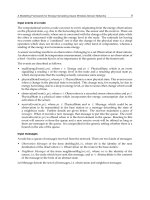
Fig. 10. Piezoelectric nonlinear vibration harvester mean electric power as a function of the
distance D between the two magnets. The symbols correspond to experimental values
measured from a prototype apparatus (see Cottone et al., 2009). The continuous curve has
been obtained from the numerical solution of the stochastic differential equation (3) with
potential (10). Both in the experiment and in the numerical solution, the stochastic force has
the same statistical properties: an exponentially correlated signal with correlation time 0.1 s.
Every data point is obtained from averaging the rms values of ten time series sampled at a
frequency of 1 kHz for 200 s. The rms is computed after zero averaging the time series. The
expected relative error in the numerical solution is within 10%. For further details on the
numerical quantities please see (Cottone et al. 2009).
Vibration Energy Harvesting: Linear and Nonlinear Oscillator Approaches
187
6.2 More general potentials
The results presented here show that, following our previous reasoning, there might be
nonlinear potentials that allow better performances in terms of power generated by a
vibration energy harvester, compared to the standard linear cantilever. Although the shape
of potential in (10) is quite peculiar, there are more general potentials that allow good
performances as well. We have explored few simpler forms, both in the bistable and in the
monostable configuration. Among the bistable ones, a popular form is represented by the
well know “Duffing oscillator” described by:
24
11
()
24
Ux ax bx
(12)
This potential U(x) is a good approximation to a number of practically available nonlinear
oscillators, like pre-bended membranes or beams.
Among the monostable (nonlinear) oscillators, as previously anticipated, we have studied
the simple class of potentials in (9) with a > 0 and n = 1,2, The n = 1 case corresponds to the
harmonic potential. In this case the dynamics is the standard linear oscillator dynamics. For
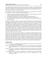
n > 1 we still have a monostable potential but the dynamics is not linear anymore. In Fig. 11
we show the displacement (x
rms
) as a function of a and n. It is evident that if a is larger than a
certain threshold (a
th
) then x
rms
increases with n and a nonlinear potential can easily
outperform a linear one, thus extending the main finding of the bistable potential (10) also to
the monostable case. On the other hand if a < a
th
then x
rms
decreases with n and the linear
case performs better than the nonlinear one.
Fig. 11. 3D plot of the displacement (x
rms
) versus a and n for the potential case in equation
(9). For further details on numerical parameters please see (Gammaitoni et al. 2009, 2010).
Sustainable Energy Harvesting Technologies – Past, Present and Future
188
It has been shown in (Gammaitoni et al. 2009, 2010) that the value a
th
is linearly dependent
on the ambient noise intensity. This result is relevant in the design of an efficient vibration
harvesting device. In fact, in real-world applications, the value of the vibration intensity is
set by the ambient and cannot be arbitrarily set. The value of the parameter a is usually fixed
by the dynamical constraints or by the material properties (stiffness, inertia, etc.) while the
value of n can sometimes be selected by a proper design of the geometry of the device itself.
Thus, once the noise intensity and a are fixed the choice of a linear (n = 1) or nonlinear
potential (n > 1) can be made in order to maximize the x
rms
and consequently the power
obtained at the device output.
7. Conclusion
In this chapter we have discussed problem of vibration energy harvesting with specific
reference to the role of linearity and nonlinearity in the potential energy characterizing the
mechanical transduction system. We have shown that linear cantilevers are clearly limited
in their practical applications and that more complex nonlinear oscillators can outperform
them in a number of realistic energy harvesting scenarios.
8. Acknowledgment
The results presented here have obtained thanks to the financial support from European
Commission (FPVII, Grant agreement no: 256959, NANOPOWER and Grant agreement no:
270005, ZEROPOWER), Ministero Italiano della Ricerca Scientifica (PRIN 2007), and
Fondazione Cassa di Risparmio di Perugia (Bando a tema - Ricerca di Base 2009,
Microgeneratori di energia di nuova concezione per l’alimentazione di dispositivi elettronici
mobili).
9. References
Ando B., Baglio S., Trigona C., Dumas N., Latorre L., Nouet P., 2010, “Nonlinear mechanism
in MEMS devices for energy harvesting applications”, Journal of Micromechanics and
Microengineering, Vol 20, 125020.
Arrieta A.F., Hagedorn P., Erturk A. and Inman D.J., 2010, "A piezoelectric bistable plate for
nonlinear broadband energy harvesting", Applied Physics Letters, Vol 97, 104102.
Barton D.A.W., Burrow S.G. and Clare L.R., 2010, “Energy Harvesting from Vibrations with
a Nonlinear Oscillator,” Journal of Vibration and Acoustics, 132, 021009.
Benjamin R. & Kawai R. (2008). Inertial effects in the Buttiker-Landauer motor and
refrigerator at the overdamped limit, Phys. Rev. E 77, 051132.
Blanter Ya.M. & Büttiker M. (1998). Rectification of Fluctuations in an Underdamped
Ratchet, Phys. Rev. Lett. 81, 4040.
Büttiker M. (1987). Transport as a Consequence of State-Dependent Diffusion, Z. Phys. B 68,
161.
Casati G.; Mejia-Monasterio C.; Prosen T.; Phys Rev Lett, 101, 016601 (2008).
Challa V.R., Prasad M.G., Shi Y. and Fisher F.T., 2008, "A vibration energy harvesting device
with bidirectional resonance frequency tunability", Smart Materials and Structures,
Vol 17, 015035.