Future Aeronautical Communications Part 14 potx
Bạn đang xem bản rút gọn của tài liệu. Xem và tải ngay bản đầy đủ của tài liệu tại đây (411.71 KB, 25 trang )
The LDACS1 Link Layer Design
313
Scenario PIAC 95%
p
ercentile of latenc
y
(
TT95-1 wa
y)
ATS Only, with
A-EXEC
ATS+AOC,
with A-EXEC
ATS Onl
y
,
without A-
EXEC
ATS+AOC,
without A-EXEC
FL RL FL RL FL RL FL RL
APT Zone 26 - - - - 125 412 126 412
APT Surface 264 - - - - 134 178 134 179
TMA Small 44 128 180 128 180 128 180 128 180
TMA Lar
g
e 53 125 187 125 187 125 187 125 187
ENR Small 45 127 180 128 180 127 180 127 180
ENR Medium 62 125 227 126 227 125 227 125 227
ENR Lar
g
e 204 125 350
161 349
125 350 129 350
ENR Super
Lar
g
e
512 125 695
212 693
125 695
212 693
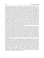
Table 5. LDACS1 responsiveness (TT95-1 way); DC size 52.
Scenario PIAC 95%
p
ercentile of latenc
y
(
TT95-1 wa
y)
ATS Only,
with A-EXEC
ATS+AOC,
with A-EXEC
ATS Onl
y
,
without A-
EXEC
ATS+AOC,
without A-EXEC
FL RL FL RL FL RL FL RL
APT Zone 26 - - - - 141 868 145 868
APT Surface 264 - - - - 139 1296 141 1296
TMA Small 44 143 639 143 639 143 988 143 988
TMA Lar
g
e 53 144 1146 144 1146
ENR Small 45 142 646 430 635 144 994 579 996
ENR Medium 62 143 724 334 719 144 1321 1472 1323
ENR Lar
g
e 204 137 706
187 708
141 1298 218 1307
ENR Su
p
er Lar
g
e 512 126 709
207 711
136 1350
272 1350
Table 6. LDACS1 responsiveness (TT95-1 way) ; minimum DC size.
Future Aeronautical Communications
314
Scenario PIAC Continuit
y
in %
ATS Only, with
A-EXEC
ATS+AOC,
with A-EXEC
ATS Onl
y
,
without A-
EXEC
ATS+AOC,
without A-EXEC
FL RL FL RL FL RL FL RL
APT Zone 26 - - - - 100 100 100 100
APT Surface 264 - - - - 100 100 100 100
TMA Small 44 100 100 100 100 100 100 100 100
TMA Lar
g
e 53 100 100 100 100 100 100 100 100
ENR Small 45 100 100 100 100 100 100 100 100
ENR Medium 62 100 100 100 100 100 100 100 100
ENR Lar
g
e 204 100 100
100 100
100 100 100 100
ENR Super
Lar
g
e
512 100 100
100 100
100 100
100 100
Table 7. LDACS1 continuity ; DC size 52.
4.4.2 Reliability
The evaluation of the LDACS1 continuity in the defined simulation scenarios shows that
LDACS1 can fulfil the continuity requirements of (EUROCONTROL & FAA, 2007c) in all
cases.
4.4.3 Scalability
The fact that LDACS1 fulfils the COCRv2 requirements in all investigated cases indicates
that the system provides the required scalability.
5. Conclusion
The objective of the LDACS1 development was to create a first protocol specification
enabling prototyping activities. It was not the goal of this development to create a final
product and it is expected that further refinements of the protocol will originate from
prototyping. However, the analysis, design, and validation of LDACS1 produced a
framework of protocols backed by formal and simulation based analysis. The goal was to
develop a protocol design providing the quality of service required for future ATM
operations.
The LDACS1 research produced a deterministic medium access approach built on the
lessons learnt from its predecessor protocols. This approach ensures that the medium access
latency is only coupled to the number of aircraft-stations served by the ground-station. The
medium access performance degrades only linearly with the number of users and not
exponentially as in the case of random access. In the LDACS1 protocol design the resource
allocation between different users is performed centralized by the ground-station while the
The LDACS1 Link Layer Design
315
resource distribution between packets of different priorities is performed locally by each
user. The effect of this approach is that the medium access sub-layer supports prioritized
channel access.
The analysis of the requirements towards the overall communication system performance
produced the justification for the use of ARQ in the LDACS1 logical link control sub-layer.
Coupling the DLS timer management to the MAC sub-layer time framing has the effect to
produce near to optimal timer management. LDACS1 can thus be considered a mature
technology proposal offering a solid baseline for the definition of the future terrestrial radio
system envisaged in AP17.
LDACS1 has now entered a new phase within the protocol engineering process going from
the development phase to the prototyping phase. The initial specification can now be
considered complete and evaluated. The next steps will be determined by the further
optimization of the protocol and the evaluation of the prototype within the context of the
Single European Sky ATM Research Programme (SESAR).
6. References
Brandes, S.; Epple, U.; Gligorevic, S.; Schnell, M.; Haindl, B. & Sajatovic, M. (2009). Physical
Layer Specification of the L-band Digital Aeronautical Communications System (L-
DACS1), Proceedings ICNS'09, ISBN 978-1-4244-4733-6, Washington DC, May
2009.
Budinger, J. & Hall, E. (2011). Aeronautical Mobile Airport Communications System
(AeroMACS), In: Future Aeronautical Communications, Plass, S., InTech, ISBN 979-
953-307-443-5
Commision of the European Communities. (2001). European transport policy for 2010: time
to decide, Office for official publications of the European Communities, ISBN 92-
894-0341-1, Brussels
Eleventh Air Navigation Conference. (2003). Report of Committee B to the Conference on
Agenda Item 7, Availabe from:
anconf11/documentation/anconf11_wp202_en.pdf
EUROCONTROL & FAA. (2007a). Action Plan 17 Future Communications Study - Final
Conclusions and Recommendations, Available from:
communications/gallery/content/public/documents/AP17_Final_Report_v11
EUROCONTROL & FAA. (2007b). Communication Operating Concept and Requirements
for the Future Radio System, Ver. 2, Available from:
communications/gallery/content/public/documents/COCR%20V2.0.pdf
EUROCONTROL & FAA. (2007c). Evaluation Scenarios, Available from: http://
www.eurocontrol.int/communications/gallery/content/public/documents/FCS_
Eval_Scenarios_V10.pdf
European Commission. (2011). Single European Sky, Available from: http://
ec.europa.eu/transport/air/single_european_sky/single_european_sky_en
.htm
Future Aeronautical Communications
316
Fistas, N. (2009). Future Aeronautical Communication System – FCI, Proceedings of Take
Off Conferenece, Salzburg, April 2009.
Gräupl, T.; Ehammer, M.; & Rokitansky, C H. (2009). LDACS1 Data Link Layer Design and
Performance, Proceedings of ICNS'09, ISBN 978-1-4244-4733-6, Washington DC,
May 2009.
Haindl, B.; Rihacek, C.; Sajatovic, M.; Phillips, B.; Budinger, J.; Schnell, M.; Lamiano, D. &
Wilson, W. (2009). Improvement of L-DACS1 Design by Combining B-AMC with
P34 and WiMAX Technologies, Proceedings of ICNS'09, ISBN 978-1-4244-4733-6,
Washington DC, May 2009.
Helfrick, A. (2007). Principles of Avionics (4th ed.). Airline Avionics, ISBN 978-1885544261,
Leesburg, VA
IATA. (2003). IATA Position on Aeronautical Air Ground Communications Needs,
Available from:
/>1_wp054_en.pdf
Kamali, B. (2010). An Overview of VHF Civil Radio Network and the Resolution of
Spectrum Depletion, Proceedings of ICNS'10, ISBN 2155-4943, Washington DC,
May 2010.
Sajatovic, M.; Haindl, B.; Epple, U. & Gräupl, T. (2011). Updated LDACS1 System
Specification. SESAR P15.2.4 EWA04-1 task T2 Deliverable D1.
Rokitansky, C H.; Ehammer, M.; Gräupl, T.; Schnell, M.; Brandes, S.; Gligorevic, S.; Rihacek,
C. & Sajatovic, M. (2007). B-AMC a system for future broadband aeronautical
multi- carrier communications in the L-band, Proceedings of 26th DASC, ISBN 978-
1-4244-1108-5, Dallas TX, Nov. 2007.
15
The LDACS1 Physical Layer Design
Snjezana Gligorevic, Ulrich Epple and Michael Schnell
German Aerospace Center (DLR)
Oberpfaffenhofen,
Germany
1. Introduction
The legacy DSB-AM (Double Sideband Amplitude Modulation) system used for today’s
voice communication in the VHF-band is far away of meeting the demands of increasing air
traffic and associated communication load. The introduction of VDL (VHF Digital Link)
Mode 2 in Europe has already unfolded the paradigm shift from voice to data
communication. Legacy systems, such as DSB-AM and VDL Mode 2 are expected to
continue to be used in the future. However, they have to be supplemented in the near future
by a new data link technology mainly for two reasons. First, only additional communication
capacity can solve the frequency congestion and accommodate the traffic growth expected
within the next 10-20 years in all parts of European airspace (ICAO-WGC, 2006). Second, the
modernization of the Air Traffic Management (ATM) system as performed according to the
SESAR ( and NextGen ( programs
in Europe and the US, respectively, heavily relies on powerful data link communications
which VDL Mode 2 is unable to support.
Based on the conclusions of the future communications study (Budinger, 2011), the ICAO
Working Group of the Whole (ICAO-WGW, 2008) has foreseen a new technology operating
in the L-band as the main terrestrial component of the Future Communication Infrastructure
(FCI) (Fistas, 2011) for all phases of flight. Hence, such L-band technology shall meet the
future ATM needs in the en-route and the Terminal Manoeuvring Area (TMA) flight
domains as well as within airports. The latter application area will be supplemented by the
AeroMACS technology at many large airports (Budinger, 2011).
A final choice of technology for the L-band has not been made yet. Within the future
communications study, various candidate technologies were considered and evaluated.
However, it was found that none of the considered technologies could be fully
recommended before the spectrum compatibility between the proposed systems and the
legacy systems has been proven. This will require the development of prototypes for testing
in a real environment against operational legacy equipment.
The future communications study has identified two technology options for the L-band Digital
Aeronautical Communication System (LDACS) as the most promising candidates for meeting
the requirements on a future aeronautical data link. The first option, named LDACS1, is a
Frequency-Division Duplex (FDD) configuration utilizing Orthogonal Frequency-Division
Multiplexing (OFDM), a highly efficient multi-carrier modulation technique which enables the
use of higher-order modulation schemes and Adaptive Coding and Modulation (ACM).
OFDM has been adopted for current and future mobile radio communications technologies,
Future Aeronautical Communications
318
like 3GPP LTE (Third Generation Partnership Project Long Term Evolution) and 4G (Fourth
Generation mobile radio system). In addition, LDACS1 utilizes reservation based access
control (Gräupel & Ehammer, 2011) to guarantee timely channel access for the aircraft and
advanced network protocols similar to WiMAX (Worldwide Interoperability for Microwave
Access) and 3GPP LTE to ensure high quality-of-service management and efficient use of
communication resources. LDACS1 is closely related to the Broadband Aeronautical Multi-
Carrier Communication (B-AMC) and TIA-902 (P34) technologies (Haindl at al., 2009).
LDACS2 is the second option which is based on a single-carrier technology. It utilizes a
binary modulation derivative (Continuous-Phase Frequency-Shift Keying, CPFSK) and thus
does not enable the use of higher-order modulation schemes. For duplexing Time-Division
Duplex (TDD) is chosen. The physical layer has some similarities to both the Universal
Access Transceiver (UAT) and the second generation mobile radio system GSM (Global
System for Mobile Communications). A custom protocol is used providing high quality-of-
service management capability. This option is a derivative of the L-band Data Link (LDL)
and the All-purpose Multi-channel Aviation Communication System (AMACS) technologies
(EUROCONTROL, 2007).
Follow-on activities required in order to validate the performance of the proposed LDACS
options and their compatibility with legacy L-band systems, finally aiming at a decision on a
single L-band technology, run under the SESAR framework (
Fistas, 2011).
2. System requirements
The choice of the radio link is based on the capacity the link should provide related
primarily to the services and applications that it should support. The radio frequency will
affect the propagation loss, whereas the channel fading in a deterministic environment may
also vary with the system bandwidth. Additionally, the interference conditions in the part of
the L-band assigned to the Aeronautical Mobile (Route) Service (AM(R)S) have to be
considered. Consequently, the development of an air-ground data link in the L-band faces
several requirements, both operational and technical.
2.1 Services and applications
Air Traffic Services (ATS) and Airline Operational Communications (AOC) services are related
to safety and regularity of flight and hence entail more stringent requirements on a future
communication system in comparison with commercial mobile communication systems.
One of the requirements for a new data link in the L-band is the suitability to support future
services and applications as described in (EUROCONTROL & FAA, 2007). The document
describes safety, information security, and performance assessments for the air traffic
services, derives high-level requirements that each service would have to meet and allocates
the requirements to the future radio system. Beside a range of parameters on which the
suitability of communication systems can be assessed, the document provides capacity
requirements estimated for different service volumes and regarding increasing air traffic
and future communication concepts.
2.2 Propagation conditions
Typically, during the flight an aircraft traverses numerous Air Traffic Control (ATC) sectors
and en-route facilities. In comparison to the VHF band used by the legacy ATC systems,
The LDACS1 Physical Layer Design
319
higher free space loss in the L-band implies smaller sector sizes. The possibility of increasing
transmitter (Tx) power is limited by the interference constraints and the amplifier
dimensions. Hence, the reuse factor of the cellular LDACS system and the interference
constraints within the L-band should be taken into account not only for the link budget
calculation but also for frequency planning for the European airspace.
Furthermore, the sector size affects the system capacity in terms of data throughput per
aircraft, but also the system design in terms of required guard times between Forward Link
(FL) and Reverse Link (RL). Whereas in the FDD configuration, as for LDACS1, the guard
times have to be guaranteed only in the random access phase, the general requirement for
guard times in a TDD based system implies a loss in the system capacity.
In en-route domain, propagation conditions are characterized by a very strong Line-Of-Sight
(LOS) component, and thus, multipath effects have only very limited influence on the
received signal quality. More severe multipath conditions in the TMA and airport domains
result in increased frequency selectivity of the channel. A broadband system may benefit
from the frequency diversity related to the multipath, whereas a narrowband system will be
affected by more severe fading on the LOS path between transmitter and receiver.
According to the publications on propagation conditions in L-band based on measurements
(Rice et al, 2004) and on theoretical considerations (ICAO-WGC, 2006), the Root Mean
Square Delay Spread (RMS-DS) remains below 2 µs in en-route case. The maximum delay
and delay spread increase in TMA and airport areas. Measurements at airports provide a
maximum RMS-DS of 4.5 µs and 90
th
percentile delay spread not exceeding 1.7 µs during
taxiing (Gligorevic et al., 2009; Matolak et al., 2008).
Taking into account an aircraft velocity of 1050 km/h in an en-route area we obtain a
maximum Doppler frequency of 972 Hz. However, due to the dominant LOS component in
en-route domain, the Doppler effect will mainly cause a Doppler shift of the carrier
frequency. Since the velocity is lower in TMA and especially in airport areas, the Doppler
spread resulting from the Doppler effect in the reflections of the signal will be lower.
According to (Bello, 1973), the reflections in the L-band can be modelled as a Rayleigh
process with a Gaussian Doppler spectrum.
2.3 Spectrum
LDACS shall operate in the lower part of the L-band, 960 - 1164 MHz. As depicted in Fig. 1,
the L-band is already utilized by several systems.
The Distance Measuring Equipment (DME) operating as an FDD system on the 1 MHz
channel grid is a major user
1
of the L-band. Parts of this band are used in some
countries by the military Multifunctional Information Distribution System (MIDS).
Several fixed channels are allocated for the Universal Access Transceiver (UAT) and the
Secondary Surveillance Radar (SSR)/Airborne Collision Avoidance System (ACAS).
Fixed allocations have been made in the upper part of the L-band for the Global
Position System (GPS), Global Orbiting Navigation Satellite System (GLONASS) and
GALILEO channels. The commercial mobile radio systems UMTS (Universal Mobile
Telecommunications System) and GSM are operating immediately below the lower
boundary of the aeronautical L-band (960 MHz). Additionally, different types of RSBN
(Pадиотехническая система ближней навигации is a Russian air navigation system)
1
DME channels are also used by the military Tactical Air Navigation (TACAN) system.
Future Aeronautical Communications
320
may be found in some parts of the world, operating on channels 960 - 1164 MHz
(SESAR JU, 2011).
978 (UAT)
1030 (SSR/
A
CAS
)
960
1213
969 1008 1053 1065 1113
DME-
X
DME-
Y
DME-
Y
JTIDS/
MIDS
1150
FIXED
1090 (SSR/
ADS-B)
GSM/
UMTS
RSBN
Type 1
1000.5
RSBN
Type 2/3
1164
960
1087
1206
L5
GPS
E5
GALILEO
1166
1217
GLONASS
L3
11961205
1186
1215 1563
1263
1558
1025
L2
E6 E1
L1
Fig. 1. Current L-band usage (SESAR JU, 2011).
The DME-free part of the spectrum is only between 960 – 975 MHz. Both LDACS systems
can use this spectrum of 15 MHz proving not to interfere with the adjacent GSM and UMTS
in the lower band, UAT at 978 MHz, and ground DME above 978 MHz. Whereas LDACS2 is
expected to operate in the 960-975 MHz frequency band, LDACS1 offers also the
opportunity to use spectral gaps between existing DME channels, thus increasing the
potential number of communication channels. In this inlay deployment option LDACS1
operates at only 500 kHz offset to assigned DME channels as exemplarily shown in Fig. 2.
One of the challenges to build up a cellular system is to find a sufficient number of channels.
In case of LDACS1, RL (air to ground) and FL (ground to air) are separated by FDD. When
selecting channels for LDACS1, co-location constraints have to be considered for the aircraft
equipment. Additionally, the fixed L-band channels at 978, 1030, and 1090 MHz must be
sufficiently isolated from LDACS1 channels by appropriate guard bands. To relax co-site
interference problems for an airborne LDACS1 receiver (Rx) in the inlay deployment option,
the frequency range 1048.5 - 1171.5 MHz, which is currently used by airborne DME
interrogators, should be used for the RL, i.e. airborne LDACS1 Tx. The proposed sub-range
for the FL is 985.5 - 1008.5 MHz, i.e. at 63 MHz offset to the RL which corresponds to the
DME duplex spacing.
The inlay concept offers the clear advantage that it does not require new channel
assignments and the existing assignments can remain unchanged. The physical layer design
The LDACS1 Physical Layer Design
321
of LDACS1, described in the following section, accounts primarily for the inlay concept
aiming for coexistence with DME system operating on adjacent channels. However, the
LDACS1 design also allows a non-inlay or a mixed inlay/non-inlay deployment without
any modifications.
-1 -0.8 -0.6 -0.4 -0.2 0 0.2 0.4 0.6 0.8 1
-180
-160
-140
-120
-100
-80
frequency [MHz]
normalized power spectral density [dBm/Hz]
DME
B-AMC
DME
L-DACS1
-1 -0.8 -0.6 -0.4 -0.2 0 0.2 0.4 0.6 0.8 1
-180
-160
-140
-120
-100
-80
frequency [MHz]
normalized power spectral density [dBm/Hz]
DME
B-AMC
DME
L-DACS1
Fig. 2. An example of LDACS1 spectrum and DME interference in the inlay deployment
scenario.
3. LDACS1 physical layer characteristics
The LDACS1 physical layer is based on OFDM modulation and designed for operation in
the aeronautical L-band (960 – 1164 MHz). Aiming for the challenging inlay deployment
option, with limited bandwidth of around 500 kHz available between successive DME
channels, and in order to maximize the capacity per channel and optimally use available
spectrum, LDACS1 is configured as a FDD system. A TDD approach would be less efficient,
since it would require large guard times due to the propagation delays and a split of the
available bandwidth into FL and RL transmission. Furthermore, by properly choosing FL
and RL frequencies from appropriate parts of the L-band, the co-location interference
situation on the aircraft can be significantly relieved.
LDACS1 FL is a continuous OFDM transmission. Broadcast and addressed user data are
transmitted on a (logical) data channel, dedicated control and signaling information is
transmitted on (logical) control channels. The capacity of the data and the control channel
changes according to system loading and service requirements. Message based adaptive
data transmission with adjustable modulation and coding parameters is supported for the
data channels in FL and RL.
LDACS1 RL transmission is based on Orthogonal Frequency-Division Multiple Access
(OFDMA) – Time-Division Multiple Access (TDMA) bursts assigned to different users on
demand. In particular, the RL data and the control segments are divided into tiles, hence
allowing the Medium-Access Control (MAC) sub-layer of the data link layer to optimize the
resource assignments as well as to control the bandwidth and the duty cycle according to
the interference conditions.
Future Aeronautical Communications
322
The channel bandwidth of 498.05 kHz is used by an OFDM system with 50 subcarriers. The
resulting subcarrier spacing of 9.765625 kHz is sufficient to compensate a Doppler spread of
up to about 1.25 kHz which is larger than typically occurring at aeronautical velocities. For
OFDM modulation, a 64-point FFT is used. The total FFT bandwidth comprising all
subcarriers is 625.0 kHz.
According to the subcarrier spacing, one OFDM symbol has duration of 102.4 µs. Each
OFDM symbol is extended by a cyclic prefix of 17.6 µs, comprising a guard interval of 4.8 µs
for compensating multipath effects and 12.8 µs for Tx windowing applied for reduction of
the out-of-band radiation. This results in a total OFDM symbol duration of 120 µs. The main
LDACS1 OFDM parameters are listed in Table 1.
Parameter Value
Effective bandwidth (FL or RL) 498.05 kHz
Subcarrier spacing 9.765625 kHz
Used subcarriers 50
FFT length 64
OFDM symbol duration
102.4
s
Cyclic prefix
Guard time
Windowing time
17.6
s
4.8 s
12.8 s
Total OFDM symbol duration
120
s
Table 1. Main LDACS1 OFDM parameters.
3.1 Frame structure
The 64 subcarriers in the FFT bandwidth are assigned to different types of symbols
providing different functionalities:
Null symbols are not transmitted. In most frame types, seven subcarriers on the left and
six on the right hand side of the spectrum carry null symbols and serve as guard bands.
In addition, the subcarrier in the center (DC subcarrier) of the spectrum is not
transmitted.
Pilot symbols are known in advance, exploited in the receiver for estimating the
transmission channel.
Symbols for reducing the Peak-to-Average Power Ratio (PAPR) are determined
depending on the data in the respective OFDM symbol. PAPR reduction symbols are
used in RL only.
Synchronization symbols are used to obtain time and frequency synchronization in the
receiver.
Preamble symbols are used for facilitating receiver Automatic Gain Control (AGC).
Data symbols are used for data transmission.
Multiple OFDM symbols are organized into frames. Depending on their functionality and
on the link direction, different frame types are distinguished.
3.1.1 FL OFDM frame types
In the FL, BroadCast (BC) and combined Data/Common Control (CC) frames are utilized.
The FL Data/CC frame comprises 50 subcarriers with 54 OFDM symbols, starting with two
The LDACS1 Physical Layer Design
323
Sync Symbol
Null Symbol
Pilot Symbol
Data Symbol
f
t
Sync Symbol
Null Symbol
Pilot Symbol
Data Symbol
Sync Symbol
Null Symbol
Pilot Symbol
Data Symbol
f
t
f
t
Fig. 3. Structure of a FL Data/CC frame.
f
t
Sync Symbol
Null Symbol
Pilot Symbol
Data Symbol
f
t
f
t
Sync Symbol
Null Symbol
Pilot Symbol
Data Symbol
Fig. 4. Structure of BC1 and BC3 sub-frames (above) and BC2 sub-frame (below).
Future Aeronautical Communications
324
synchronization OFDM symbols followed by 52 OFDM symbols carrying data and pilot
symbols, as depicted in Fig. 3. Subtracting the total number of 158 pilot symbols results in a
total data capacity of 2442 symbols per FL Data/CC frame. The mapping of CC information
and data onto this frame type is described later in this section.
An FL BC frame consists of three consecutive sub-frames (BC1/BC2/BC3), in which the
Ground Station (GS) broadcasts signaling information to all active Airborne Stations (ASs)
within its coverage range. Fig. 4 shows the structure of these sub-frames. In the BC1 and
BC3 sub-frames, two of 15 OFDM symbols are used for synchronization. In the remaining 13
OFDM symbols, 48 carriers are modulated by pilot symbols and 602 remain for data
transmission. The BC2 sub-frame is eleven OFDM symbols longer than the BC1/3 sub-frame
and provides a capacity of 1120 data symbols.
Note that in the FL frames, no PAPR reduction symbols are inserted as the power amplifier
used in the GS is assumed to provide sufficient linearity.
3.1.2 RL OFDM frame types
To realize multiple-access via OFDMA-TDMA in the RL, the transmission is organized in
segments and tiles rather than in OFDM frames and sub-frames as in the FL. The usage of
tiles enables the optimization of the resource assignments by the MAC sub-layer.
Furthermore, bandwidth and duty cycle can be optimally selected according to the
interference conditions.
As illustrated in Fig. 5, one tile, representing the smallest allocation block in the RL, spans 25
symbols in frequency and six symbols in time direction in the time-frequency plane. It
comprises four PAPR reduction symbols and twelve pilot symbols. This leads to a data
capacity of 134 data symbols per tile.
f
t
PAPR Symbol
Pilot Symbol
Data Symbol
f
t
f
t
PAPR Symbol
Pilot Symbol
Data Symbol
Fig. 5. Structure of a data tile in the RL.
The values of the PAPR reduction symbols are optimized in dependence on the data content
such that the entire OFDM symbol, i.e. 24 data symbols and one PAPR reduction symbol,
produces a minimal PAPR. In the first and the last OFDM symbol in a tile, PAPR is
minimized by optimizing the phases of the pilot symbols in a way that the contribution of
the pilot symbols to the PAPR is minimal.
The tiles of the data segment are subsequently positioned left of the DC subcarrier and
mirrored versions of the tiles are positioned right of the DC subcarrier. The length of the
data segment is kept variable by allocating a variable number of tiles to the data segment.
This structure also supports a flexible assignment of resources to different ASs by assigning
different tiles or different blocks of subsequent tiles to different ASs.
Signaling information like resource allocation requests is transmitted in the Dedicated
Control (DC) segment. A DC segment has the same tile structure as the RL data segment.
The LDACS1 Physical Layer Design
325
However, it starts with a so called synchronization tile, spanning five OFDM symbols in
time direction and 51 subcarriers, including the DC subcarrier, in frequency direction. The
synchronization tile as illustrated in Fig. 6 starts with an AGC preamble, followed by two
OFDM synchronization symbols. The forth and fifth OFDM symbol consist of pilot symbols
only. This synchronization tile provides a possibility for an AS to execute seamless
handover, when entering a new LDACS1 cell.
f
t
Sync Symbol
Null Symbol
Pilot Symbol
AGC Preamble
f
t
f
t
Sync Symbol
Null Symbol
Pilot Symbol
AGC Preamble
Fig. 6. Structure of one synchronization tile.
After the synchronization tile, an AGC preamble is inserted in the DC segment. This
additional AGC preamble is necessary, since an AS, performing seamless handover is not
yet power-controlled with the new GS, leading to a different power level at the receiving
GS, compared to the signals from the other ASs. Within the remainder of the DC segment,
exactly one tile is assigned to each AS within the cell. The preceding AGC preamble is
transmitted by the same AS which transmits the first tile in the DC segment. The length of a
DC segment is variable, depending on the number of ASs within the LDACS1 cell. As an
example, one DC segment comprising six tiles corresponding to six active ASs within one
cell, is depicted in Fig. 7.
Sync Symbol
Null Symbol
Pilot Symbol
Data Symbol
AGC Preamble
Tile Segmentation
PAPR Symbol
f
t
Sync Symbol
Null Symbol
Pilot Symbol
Data Symbol
AGC Preamble
Tile Segmentation
PAPR Symbol
Sync Symbol
Null Symbol
Pilot Symbol
Data Symbol
AGC Preamble
Tile Segmentation
PAPR Symbol
f
t
f
t
Fig. 7. Structure of one DC segment.
Besides the mentioned seamless handover, LDACS1 provides additional opportunities for
handover by means of two consecutive RL Random Access (RA) opportunities, in which an
AS can send its cell entry request to the GS (see Fig. 8). Propagation guard times of up to
1.26 ms precede and follow each RA frame. The propagation guard time of 1.26 ms
corresponds to a maximal AS-GS distance of 200 nm. When transmitting a cell entry request,
an AS is not yet synchronized to the GS, which means that the distance between the AS and
Future Aeronautical Communications
326
the GS is unknown. Hence, the distance can take values up to 200 nm which corresponds to
the maximum LDACS1 cell size. The unknown propagation time differences are well
compensated by the inserted guard times, guaranteeing that the cell entry request does not
superimpose at the receiving GS with signals from other ASs within the cell.
RA Opportunity 1 RA Opportunity 2
RA Frame
3,36 ms
840 µs
1,26 ms1,26 ms
RA Frame
3,36 ms
840 µs
1,26 ms1,26 ms
Guard Guard
RA Opportunity 1 RA Opportunity 2
RA Frame
3,36 ms
840 µs
1,26 ms1,26 ms
RA Frame
3,36 ms
840 µs
1,26 ms1,26 ms
RA Frame
3,36 ms
840 µs
1,26 ms1,26 ms
Guard Guard
RA Frame
3,36 ms
840 µs
1,26 ms1,26 ms
Guard Guard
Fig. 8. Random access opportunities.
In Fig. 9, the structure of a RA frame itself is depicted. The first OFDM symbol represents
the AGC preamble, the following two OFDM symbols contain synchronization sequences,
while the remaining four OFDM symbols carry data, PAPR reduction symbols and pilot
symbols. These four OFDM symbols use only 27 subcarriers (including the DC subcarrier),
which leads to larger guard bands with 19 empty subcarriers on the left side and 18 on the
right side.
f
t
Sync Symbol
Null Symbol
Pilot Symbol
Data Symbol
AGC Preamble
PAPR Symbol
f
t
f
t
Sync Symbol
Null Symbol
Pilot Symbol
Data Symbol
AGC Preamble
PAPR Symbol
Fig. 9. Structure of random access frame.
3.1.3 Framing structure
In the FL, nine CC/Data frames are combined to one Multi-Frame (MF). The assignment of
the nine frames within one MF either for user data or for common control information is
variable. Starting with the fifth frame, one up to four frames can be allocated for common
control information. The remaining frames contain user data. The mapping of modulated
symbols onto the frames is performed block wise. These blocks are called Physical layer
Protocol Data Units (PHY-PDUs). In general, three PHY-PDUs are mapped onto one
Data/CC frame in FL MFs.
Each MF in the RL starts with a RL DC segment, followed by a RL data segment. The size of
the DC segment, and thus also the size of the data segment is variable. The minimum size
DC segment comprises one synchronization tile and the subsequent AGC preamble,
followed by two tiles, corresponding to the case of one or two ASs within the cell. Since the
extension of the DC segment over the entire MF is not reasonable, the maximum size of the
DC segment is limited to 52 tiles. The remainder of the frame is filled up with the data
segment. In the RL, one PHY-PDU is always mapped onto one tile.
The LDACS1 Physical Layer Design
327
The MF structure for FL and RL is shown in Fig. 10. The reference synchronization point for
the FL and RL is the beginning of the MF. It is noticeable that the common control
information in the FL and the dedicated control information in the RL are transmitted
interleaved rather than simultaneously. The temporal shift of the FL control information
allows the requests sent in the RL DC segment to be answered already in the FL CC frames
of the same MF. Similarly, resource allocations transmitted in the FL CC frames can already
be used in the next RL MF.
FL
Frame
6.48 ms
variable
DC Data
variable
Data
CC Data
0.72 ms
Tile
RL
FL
Frame
6.48 ms6.48 ms
variable
DC Data
variable
DC Data
variablevariable
Data
CC Data
0.72 ms0.72 ms
Tile
RL
Fig. 10. Multi-Frame structures.
On top of the MF structure, a Super-Frame (SF) structure is provided. In the FL, one SF
contains a BC frame of duration 6.72 ms, and four MFs, each of duration 58.32. In the RL,
each SF starts with two opportunities for transmitting RL RA frames followed by four MFs.
The start of the FL BC frame is synchronized to the start of the RL RA. The SF structure is
summarized graphically in Fig. 11.
DC
Multi-Frame 1
(58.32 ms)
Multi-Frame 2
(58.32 ms)
Multi-Frame 3
(58.32 ms)
Multi-Frame 4
(58.32 ms)
RA
Super-Frame (240 ms)
RA 1 RA 2
Multi-Frame 1
(58.32 ms)
Multi-Frame 2
(58.32 ms)
Multi-Frame 3
(58.32 ms)
Multi-Frame 4
(58.32 ms)
BC
BC
FL
RL
6.72 ms
CC
variable
Data
Data
Data
variable
DC
Multi-Frame 1
(58.32 ms)
Multi-Frame 2
(58.32 ms)
Multi-Frame 3
(58.32 ms)
Multi-Frame 4
(58.32 ms)
RA
Super-Frame (240 ms)Super-Frame (240 ms)
RA 1 RA 2 RA 1 RA 2
Multi-Frame 1
(58.32 ms)
Multi-Frame 2
(58.32 ms)
Multi-Frame 3
(58.32 ms)
Multi-Frame 4
(58.32 ms)
BC
Multi-Frame 1
(58.32 ms)
Multi-Frame 2
(58.32 ms)
Multi-Frame 3
(58.32 ms)
Multi-Frame 4
(58.32 ms)
BC
BC
FL
RL
6.72 ms6.72 ms
CC
variable
Data
Data
Data
variable
Fig. 11. Super-Frame Structure.
3.2 Coding and modulation
Different robust coding schemes proposed for LDACS1 should cope with the interference
the transmit signal is exposed to. Primarily for small coding block sizes, a convolutional
code of rate 1/3, followed by a bit interleaver is defined. For larger coding block sizes, a
concatenated coding scheme consisting of a rate 0.9 Reed-Solomon (RS) code and a rate 1/2
Future Aeronautical Communications
328
convolutional code is employed. Again, the convolutional coder is followed by a bit
interleaver. In addition, a byte interleaver between the two coders is inserted. The rate of the
convolutional code can be changed from 1/2 to 2/3 or 3/4 by puncturing. The coding
scheme is depicted in Fig. 12.
Fig. 12. Concatenated coding scheme.
For the subsequent modulation, Quaternary Phase-Shift Keying (QPSK) modulation, 16
Quadrature Amplitude Modulation (QAM), and 64 QAM are available.
The coding rates and the modulation scheme in the data frames can be adapted, based on
the current channel and interference conditions, maximizing the transmission capacity.
Therefore two Adaptive Coding and Modulation (ACM) modes are defined:
Cell-specific ACM mode, which means that data for all users within one cell are
encoded and modulated with a fixed scheme, and
User-specific ACM mode, which means that separate coding and modulation schemes
are applied for the data of different users.
In both modes, QPSK, 16QAM, and 64QAM are available. The rate of the convolutional code
can be changed from 1/2 to 2/3 or 3/4. From the possible 9 combinations 8 are available
2
as
ACM schemes.
For the particular frame types, the following coding and modulation scheme is chosen:
In FL data frames, the concatenated coding scheme is mandatory. The coding rate and
the modulation scheme is variable, both ACM modes are available. In case of cell-
specific ACM, the information about the chosen coding and modulation scheme is
transmitted in the BC frame. In case of user-specific ACM, the GS transmits the
information about coding and modulation for different ASs via the coding and
modulation scheme FL map in the CC information block.
In RL data segments, the concatenated coding scheme is mandatory. The coding rate
and the modulation scheme is variable, user-specific ACM is available. The selection of
a coding and modulation scheme for a certain AS is carried out by the GS and
communicated when assigning resources to this AS.
For the BC sub-frames and the CC frames, again the concatenated coding scheme is
employed. To guarantee an adequate protection of the control information,
convolutional coding rate 1/2 and QPSK modulation is mandatory.
The data in the RA frames and DC segment is encoded with the rate 1/3 convolutional
coder, which is suitable for the small block sizes in these frames. QPSK modulation
scheme is mandatory.
3.3 Reduction of out-of-band radiation
High out-of-band OFDM side lobes may cause harmful interference at the Rx of other L-
band systems and have to be reduced. For that purpose, Tx windowing is applied in order
to smooth the sharp phase transitions between consecutive OFDM symbols which cause
out-of-band radiation.
2
Only the combination of 16QAM with rate 3/4 coding has been omitted.
RS Coder
Byte
Interleaver
Convolutio
nal Coder
Bit
Interleaver
The LDACS1 Physical Layer Design
329
Fig. 13. Tx windowing principle.
As illustrated in Fig. 13, the OFDM symbol is extended by a cyclic prefix of total length
T
cp
=T
w
+T
g
. One part of the cyclic prefix serves as guard interval of length T
g
to compensate
multipath propagation on the radio channel. The second part is of length T
w
and contains
the leading edge of the window. In addition, the OFDM symbol is extended by a cyclic
suffix which contains the trailing edge of the window of length T
w
. This approach
guarantees that Tx windowing does not affect the useful part of the OFDM symbol
including guard interval. To keep the overhead induced by extending the OFDM symbol
duration at a minimum, subsequent OFDM symbols overlap in those parts containing the
leading and trailing edges of the window. For LDACS1, a raised-cosine window with roll-
off factor = 0.107 is proposed.
3.4 Receiver design
When deployed as an inlay system, signals of existing L-band systems may cause severe
interference onto the LDACS1 Rx. Especially DME systems operating at a small frequency
offset to the LDACS1 channel represent a source of strong interference. Two promising
techniques, aiming at mitigation of the influence of interference onto LDACS1, are presented
in the following. In addition, the effect of the interference and the proposed interference
mitigation to the estimation of the transmission channel is examined.
3.4.1 Over-sampling
RF and IF filters in the selective stages of the LDACS1 Rx successively reduce interference
contributions received outside the LDACS1 bandwidth. Since the interference signal
power can be very high, it may be impossible to completely remove this out-of-band
interference power. In particular, due to the relatively large occupied bandwidth of the
DME signal, the spectra of DME Txs operating at ±0.5 MHz offset from the LDACS1
channel partly fall into the LDASC1 Rx bandwidth. Subsequent sampling of the filtered
Rx signal in the A/D-converter with the native sampling period leads to periodic
repetitions of the interference spectra in the frequency domain in distances of multiples of
the FFT bandwidth B
FFT
. In the case without interference, the filtered Rx signal is band-
limited by B
FFT
. Sampling with T
sa
= 1/B
FFT
does not lead to aliasing effects. However, the
Nyquist sampling theorem is not fulfilled for the interference signal. The remaining out-
of-band interference signal is not band-limited to B
eff
, hence due to aliasing after Rx FFT
operation the undesired signal parts fall into the LDACS1 bandwidth. This can be avoided
by over-sampling the time domain Rx signal at least by a factor of four, resulting in an
increased spacing between the periodic repetitions in the frequency domain and reduced
aliasing effects. The over-sampled Rx signal is then transformed to the frequency domain
by FFT with the size increased according to the over-sampling factor. For further signal
processing, only the relevant subcarriers in the LDACS1 system bandwidth are
considered. All other subcarriers are discarded.
Future Aeronautical Communications
330
3.4.2 Pulse blanking
Pulse Blanking (PB) is a well-known approach for reducing pulsed interference such as
DME interference. It has already been applied for reducing DME interference in the E5- and
L5-bands used by satellite navigation systems (Gao, 2007) and for reducing impulsive noise
in OFDM systems (Zhidkov, 2006).
In LDACS1, PB is applied to the digitized Rx signal after A/D conversion. When the
amplitude of the over-sampled Rx signal exceeds a pre-defined threshold T
PB
the
corresponding samples are blanked, i.e. set to zero. Besides the DME interference, the
blanked samples also comprise the desired OFDM signal and noise. Hence, the threshold
T
PB
has to be chosen carefully. When choosing it too low, the corruption of the desired signal
exceeds the benefit of reducing the interference power, whereas a too high threshold leads
to a strong remaining interference power. A suitable criterion for optimally setting T
PB
is the
Signal-to- Interference-and-Noise ratio (SINR) (Zhidkov, 2006).
Due to high PAPR in OFDM systems, peaks of the desired OFDM signal and DME pulses
cannot be clearly distinguished. For an unambiguous detection of interference pulses in the
Rx signal, a correlation of the Rx signal with a known interference pulse has been proposed
in (Brandes & Schnell, 2009).
An algorithm for diminishing the harmful PB influence onto the useful OFDM signal was
presented in (Brandes et al., 2009). It is based on the idea, that the PB impact on the OFDM
signal can be determined exactly when representing PB as a windowing operation. The
window function is a rectangular window that exhibits notches at those positions where the
Rx signal is blanked. Recalling that the shape of the window determines the spectrum of the
OFDM subcarriers, the subcarrier spectra can be determined and the distortion induced by
PB is identified as Inter-Carrier Interference (ICI). ICI can easily be reduced by subtracting
the known impact of all other subcarriers from the considered subcarrier as applied for
example for reducing ICI in OFDMA systems induced by frequency offsets (Fantacci et al.,
2004).
3.4.3 Channel estimation
As basic channel estimation algorithm in LDACS1, a pilot-aided linear interpolation is
proposed. In order to make channel estimation robust towards interference the pilot tones in
frequency direction are spread over all subcarriers in order to reduce the number of pilot
tones that would be affected by a strong DME interference pulse from the adjacent DME
channel. In RL, such pilot tone placing is not possible due to the OFDMA approach. In this
case the pilot tones have to be placed of the edges of each tile. These pilot distances in time
and frequency direction have been chosen in accordance with the expected Doppler shifts
and maximal delay times in the case of multipath propagation. To improve channel
estimation, pilot boosting is applied. In this case, the power of the pilot symbols is increased
by 4 dB over the average power of each data symbol.
A more sophisticated approach for estimating the transmission channel is Wiener filtering.
The coefficients of the Wiener interpolation filter are derived by minimizing the Mean-
Squared-Error (MSE) between the actual and the estimated channel coefficients. This leads
to an optimal noise suppression, given the noise variance and channel statistics. In (Epple &
Schnell, 2010), it was proposed to incorporate an equivalent noise term, comprising the
additive white Gaussian noise and the estimated DME interference, into the Wiener filter. If
interference mitigation like PB is applied, the variance of the induced ICI can be
The LDACS1 Physical Layer Design
331
incorporated into the Wiener filtering (Epple et al., 2011). Both approaches turned out to
improve the channel estimation performance remarkably.
4. Conclusion
LDACS1 is the broadband candidate for the future L-band communications system which
covers the air-ground link within the FCI. The design of LDACS1 is based on the multi-
carrier technology OFDM, a modern communications technology which is highly flexible
and efficient. In comparable application domains, like mobile radio communications, OFDM
is the current state-of-the-art solution and is also foreseen for the next generation of mobile
radio systems.
The LDACS1 design is based on existing multi-carrier standards, like WiMAX and P34.
However, due to the operational requirements on an aeronautical communications system,
the propagation conditions, and the interference environment in L-band a specific OFDM
solution had to be designed. Investigations of the LDACS1 system performed by computer
simulations have proven the suitability of the LDACS1 design for use in the L-band
(Brandes et al., 2009; Epple & Schnell, 2010; Epple et al., 2011). Even for the challenging
inlay deployment scenario, LDACS1 is expected to work according to the requirements
without causing harmful interference to the legacy L-band systems. With that, LDACS1
shows that aeronautical communications can profit from the developments in related fields
and can achieve efficient usage of the scarce spectrum resources currently available for
communications within aviation.
5. References
Bello P.A. (1973). Aeronautical Channel Characterization, IEEE Trans. on Communications,
vol. COM-21, no 5, pp. 548-563, May 1973
Brandes, S.; Epple, U. & Schnell, M. (2009). Compensation of the Impact of Interference
Mitigation by Pulse Blanking in OFDM Systems, Proceedings of IEEE Global
Telecommunications Conference 2009, Honolulu, Hawaii, USA, November 28-
December 4, 2009
Brandes, S. & Schnell, M. (2009). Interference Mitigation for the Future Aeronautical L-Band
Communication System, Proceedings of 7
th
International Workshop on Multi-Carrier
Systems & Solutions 2009, Herrsching, Germany, May 5-6, 2009
Budinger J.M. (2011). Aeronautical Mobile Airport Communications System (AeroMACS),
Future Aeronautical Communications, Simon Plass (ed.), ISBN 979-953-307-443-5
Epple, U.; Shibli, K. & Schnell, M. (2011). Investigation of Blanking Nonlinearity in OFDM
Systems, Proceedings of IEEE International Communications Conference 2011, Kyoto,
Japan, June 5-9, 2011
Epple, U. & Schnell, M. (2010). Channel Estimation in OFDM Systems with Strong
Interference, Proceedings of 15th International OFDM Workshop 2010, pp. 26-30,
Hamburg, Germany, September 1-2, 2010
EUROCONTROL (2007). Future Communications Infrastructure - Technology
Investigations. Description of AMACS, v1.0, 2007. Available from
/>.html. Information available also on
Future Aeronautical Communications
332
EUROCONTROL & FAA (2007). Communications Operating Concept and Requirements for
the Future Radio System, (COCR) version 2
Fantacci, R.; Marabissi, D. & Papini, S. (2004). Multiuser Interference Cancellation Receivers
for OFDMA Uplink Communications with Carrier Frequency Offset, Proceedings of
IEEE Global Telecommunications Conference 2004, pp. 7081-7085, Dallas, Texas, USA,
November 29-December 3, 2004
Fistas N. (2011). Aeronautical Future Aeronautical Communications: The Data Link
Component, Future Aeronautical Communications, Simon Plass (ed.), ISBN 979-
953-307-443-5
Gao, G.X. (2007). DME/TACAN Interference and its Mitigation in L5/E5 Bands, Proceedings
of ION Institute of Navigation Global Navigation Satellite Systems Conference, Fort
Worth, Texas, USA, September 25-28, 2007
Gligorevic, S., Zierhut, R., Jost, T., Wang, W. (2009). Airport Channel Measurements at
5.2GHz, In Proceedings of the 3rd European Conference on Antennas and Propagation
(Eucap), March 2009
Gräupel T. & Ehammer M. (2011). The LDACS1 Link Layer Design, Future Aeronautical
Communications, Simon Plass (ed.), ISBN 979-953-307-443-5
Haindl, B.; Rihacek, CHr.; Sajatovic, M.; Phillips, B.; Budinger, J.; Schnell, M.; Lamiano, D. &
Wilson, W. (2009). Improvement of L-DACS1 Design by Combining B-AMC with
P34 and WiMAX Technologies, Integrated Communications Navigation and
Surveillance Conference (ICNS 2009), Arlington, VA, USA, May 2009
ICAO, ACP-WGC (2006). Report of the Tenth Meeting of ICAO ACP Working Group C,
Montreal, 13-17 March 2006
ICAO, ACP-WGC (2011). FCS Phase II Results Paper 3 - Detailed Technology Investigations,
Working Group C – 11th meeting, Brussels, Belgium, 18 – 20 September 2006
IICAO, ACP-WGW (2008). Report of the Working Group of the Whole, Second Meeting,
Montreal, 21 to 25 April 2008
Matolak D.W., Sen I., Xiong W. (2008). The 5GHz Airport Surface Area Channel Part I,
Measurement and Modeling Results for Large Airports, IEEE Trans. Vehicular Tech.,
vol. 57, no. 4, pp. 2014–2026, 2008
Rice, M.; Davis, A.; Bettweiser, C. (2004). Wideband Channel Model for Aeronautical
Telemetry; IEEE Trans. On Aerospace and Electronic Systems, vol. 40, no.1, January
2004
SESAR JU (2011). Updated LDACS1 System Specification. Information available at
www.sesarju.eu
Zhidkov, S.V. (2006). Performance Analysis and Optimization of OFDM Receiver with
Blanking Nonlinearity in Impulsive Noise Environment, IEEE Transactions on
Vehicular Technology, Vol. 55, No. 1, (January 2006), pp. 234–242
Part 5
Visions for Aeronautics
16
IFAR – The International Forum
for Aviation Research
Richard Degenhardt, Joachim Szodruch and Simon Plass
German Aerospace Center (DLR)
Brunswick, Cologne and Oberpfaffenhofen,
Germany
1. Introduction
The future challenges of air transport motivated the leading worldwide aviation research
institutions to found IFAR - the International Forum for Aviation Research which aims at
discussing the global aeronautical challenges and the set-up of a Framework outlining
worldwide research. Climate change is currently the most relevant topic and was the
motivation to set up IFAR. However, IFAR also addresses other topics relevant for a global
air transport system (e.g. noise, security, safety, efficient operations). IFAR connects and
represents worldwide aviation research and provides a common voice for their members in
the international dialogue. IFAR interacts with the society, global politics and industry and
takes up the challenges identified by them.
The idea of IFAR was born at the Berlin Summit 2008 where key leaders of 12 international
aeronautical research organisations met to address the question of future Air Transport in
the context of climate change. In this regard, the participants agreed that any research and
strategy contributing to new solutions will have to reconcile the increasing need for
international mobility in a globalized work-sharing economy with the challenge of
simultaneously developing new solutions to balance the climate effects of the accompanying
world-wide air traffic growth. At the second Berlin Summit in 2010 16 international
aeronautical research organisations met and eventually set up IFAR (IFAR, 2008).
The main objective of IFAR is connecting global research establishments and setting up a
Framework agreed upon by research institutions worldwide. Within this document
promising technologies will be identified which contribute to an improved Air Transport
System. IFAR as research representative focuses on the identification of new technologies up
to the development of Technology Readiness Level (TRL) level 6. The IFAR members agreed
at the first IFAR Summit 2010 to focus in 2010/2011 on the topics related to climate change
and to present potential solutions for an ecologically and economically efficient air transport
system. Within the next years this Framework is going to be extended by taking the other
topics noise, safety, security and efficient operations into account (Szodruch et al., 2011a).
This paper deals with the objectives, state-of-the art and future planning of IFAR. It
highlights first ideas for improved technologies in the area Aeronautical Communications
which is the main topic of this book. Aeronautical Communications is one relevant topic
considered in IFAR which plans to contribute to an improved air transport system on a
Future Aeronautical Communications
336
worldwide level. A communications network is to be created which meets the requirements
of the aviation industry of the future. Here, the data streams must, above all, flow reliably
between the aircraft and the ground, and this must take place both in remote regions over
the oceans and the poles as well as in crowded conurbations. Supplementary information
means that such a new communications network can sustainably improve safety standards
in aviation and also reduce environmental impact through optimised flight paths for
example. Within Section 6 the IFAR future aeronautical communications aspects will be
spotlighted.
2. IFAR history
The Forth Assessment Report of the International Panel on Climate Change (IPCC) has
stirred an intensive public debate on future aeronautical research challenges and policies. By
an initiative of the German Aerospace Center (DLR) a Summit was held in 2008 in Berlin as
a response. 12 key international leaders in aeronautical research met to address the question
of the Air Transport of the Future in the context of climate change. In this regard, the
conference participants agreed that any research and strategy contributing to new solutions
will have to reconcile the increasing need for international mobility in a globalized, work-
sharing economy with the challenge of simultaneously developing new solutions to balance
the climate effects of the accompanying world-wide growth in air traffic. The IPCC report
identifies aviation to contribute 2–3 percent of today’s total global anthropogenic CO2
emissions. This prompted the International Air Transport Association (IATA) to set the long
term challenge of Zero Emission Aviation by 2050 and emphasised the importance of
addressing these challenges on a global level. Using the IPCC report and the latest research
results on climate change as a basis, the Berlin Summit participants acknowledged the need
for new solutions addressing both mid-term as well as long-term perspectives. Some
solutions, such as the enhanced efficiency of aircraft and air traffic management systems
have already resulted in major technological advancements and increased operational
capabilities. Nonetheless, as air transport faces increasing demands, these topics remain to
be core areas of aeronautical research. Accordingly, international research establishments
are key actors, particularly in approaching the long-term and, thus, pre-industrial questions
of research and development. The participants of the Berlin Summit welcomed this first
event as a unique international forum to enhance discussion of the strategic challenges in
aeronautical research. They agreed to establish an international platform for a dialogue to
coincide with International Air Shows and with meetings all over the world.
At the Berlin Summit in 2010 key leaders of 16 international aeronautical research
organisations met the second time and gave this forum the name IFAR which stands for
International Forum for Aviation Research. The attendees continued the discussion on the
topics related to climate change and agreed to develop a common Research Framework
which represents the Aviation Research worldwide. The kind of organisation is under
discussion and will be defined in the short future.
The outcome of the IFAR summit was summarised by the participants with in a declaration
which is published at the IFAR website www.ifar.aero.
3. IFAR objectives
The objectives for IFAR were discussed at the last IFAR Summit in 2010 and the outcome
was published within a declaration. These results are at this time first ideas which will be
finalised in the short future. This section gives a summary of this declaration.