Heat Analysis and Thermodynamic Effects Part 10 pptx
Bạn đang xem bản rút gọn của tài liệu. Xem và tải ngay bản đầy đủ của tài liệu tại đây (798.44 KB, 30 trang )
Integral Transform Method Versus Green Function Method
in Electron, Hadron or Laser Beam - Water Phantom Interaction
259
2
0
ij
ij
ij
Kx
kx K x
xx
(4)
Equation (4) provides a series of positive eigenvalues
,
j
jN
and eigenfunctions
,
ij
i
Kx
of the differential operator:
kx
xx
, [7]. The eigenfunctions were necessary
for solving equation (2).
The solution of equation (4) has the form:
00
22
,,
ji i i ji i i
ij
ii i
ii
k x mx k x mx
Kx AJ BY
j
N
mm
(5)
Where:
iii
c
and J
0
and Y
0
are the Bessel and Weber functions respectively.
After the application of the integral operator K
i
(x) equation (4) becomes:
2
,
,,
i
j
i
jj ii j
i
Tt
utc f t
t
(6)
where:
1
1
,(,),
i
i
x
i
i
jj
j
x
ut TxtKxdx
C
1
1
,,,
i
i
x
j
jj
j
x
f
t
f
xtK x dx
C
and
j
C is a normalization factor.
Here we have [7]:
1
1
2
0
() (,)
i
i
x
n
jijij
i
x
CKxdx
. (7)
In the same manner, one can apply the functions:
(,)
kk
Ky
and
(,)
ll
Kz
, which satisfy the
equations:
2
2
2
2
2
2
,
,0
,
,0
kk
kk k
ll
lll
Ky
Ky
y
Kz
Kz
z
(8)
This next gives:
(,) cos( )(/ )sin( )
ll l l l
Kz zhk z
, with, k being the thermal
conductivity and h the heat transfer coefficient .
Heat Analysis and Thermodynamic Effects
260
Then, the following equation is inferred:
222
ˆˆˆ
( , ,,) (, ,,) ( , ,,)
ˆ
ˆ
(,,,)
(,,,)
ji j k l ki j k l li j k l
ij
kl
i
ii
TtTtTt
Tt
fxyzt
c
t
(9)
Where from it follows:
2
13
23
1
()()()
/2
/2
/2 /2
ˆ
(,,,)
(,,,) ( ,) ( ,) ( ,)
jkl
i
i
ijkl
CCC
y
xz
ij j k k l l
xy z
Tt
T x y z t K x K y K z dxdydz
(10)
In order to eliminate the time parameter t, we apply the direct and inverse Laplace
transform to equation (9).
If we have, like in most cases:
0
(,,,) (,,)[() ( )]fxyzt fxyz ht ht t
, one can get the solution:
22 2 22 2
0
22 2
() ()()
1
0
()
111
(,,,) [1 (1 )( )]
(,,) (,) (,) (,)
jl k jl k
jl k
ttt
i
jkl
jkl ijj kk ll
Txyzt e e ht t
gKxKyKz
(11)
where:
2
13
23
1
()()()
/2
/2
1
0
/2 /2
(,,)
(,,,) ( ,) ( ,) ( ,)
jkl
i
i
jkl
CCC
y
xz
n
iijjkkll
i
xy z
g
f
x y z t K x K y K z dxdydz
(12)
stands here for the thermal diffusivity. We point out that our semi-analytical solution
becomes analytical, if we observe the, after 10 iterations, the solution becomes convergent
(we have values of temperature less than 10
-2
K for: i>10;j>10 and k>10). Under these
conditions equation (10) becomes:
22 2 22 2
0
22 2
10 10 10
() ()()
1
0
()
111
(,,,) [1 (1 )( )]
(,,) (,) (,) (,)
jl k jl k
jl k
ttt
i
jkl
jkl ijj kk ll
Txyzt e e ht t
gKxKyKz
(13)
3. Application of the theory: Laser-assisted hadron and electron beams
therapy
It is well known [8] that the hadrons therapy (e.g. with protons) is much more suitable and
efficient compared to electrons therapy, because the absorption curve is (in this case) a Dirac
function. We can solve easily the heat equation for this case, and we obtain the temperature
field in Fig.1. - (The Dirac absorption function is at 4 cm from the surface). Here dT is the
temperature variation (dT=T
f
-T
i
), rather than the absolute temperature.
Integral Transform Method Versus Green Function Method
in Electron, Hadron or Laser Beam - Water Phantom Interaction
261
T
f
and T
i
are the final and initial temperatures respectively.
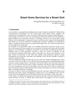
Fig. 1. Thermal field distribution in case of 1 MeV proton beam irradiation of a water
phantom, for 120 sec.
Fig. 2. Thermal field in water submitted to cw CO
2
laser irradiation for 50 sec.
Heat Analysis and Thermodynamic Effects
262
The power of the cw CO
2
laser beam was P= 1W.
It is known from experience [8] that proton therapy is more efficient in the “presence” of a
laser beam. We plotted in figure 2 the thermal gradient in water produced by cw CO
2
laser
irradiation for 50 sec. (P = 1W). In Fig. 3 we presented the temperature field in water
produced by an electron beam, when the “steady - state” is achieved. The white color
corresponds to an increase of temperature, and the black color represents a decrease of
temperature. We have use sub-domains of 0.25 cm. The thickness of the water phantom was
0.25 cm, and was contained in a plastic cube with a mass density close to 1 g/cm
3
. Figure 3
was obtained using eq. (13).
Fig. 3. Temperature field in water produce by an electron beam, when the “steady- state” is
achieved.
The white color corresponds to the temperature increase while, the black color represents
the temperature decrease. We have used sub-domains of 0.25 cm length.
4. The green function method
We start from the heat equation:
[()] [()] [()] (,,)
TTT
xyz
xXyyzz
KT KT KT Sx
y
z
(14)
where S(x, y, z) is proportional with the absorbed dose. We consider [9], the case of a 10
MeV electron beam interactions with water. We have:
10
(,,) (,). ()Sxyz Kyz D x
(15)
where according to experimental data from our laboratory:
2345
10
( ) 83.2337 18.6522 15.1080 4.1417 0.3506Dx x x x x
(16)
Integral Transform Method Versus Green Function Method
in Electron, Hadron or Laser Beam - Water Phantom Interaction
263
Here x stands for the direction of electron propagation. We will consider the radiation
(electron beam) normal to water surface.
From the standard theory of Green function applied to multi-layer structures, we have:
12
12 12
12 12
n
ll
ll ll
nn
kk k kk k
nn
ll l
l
K
(17)
where l
i
is the length and k
i
is the thermal conductivity of the i-th layer.
We introduce the area of the layer A
i
:
11 22 11 22
12
nn nn
n
KA KA KA KA KA KA
AA A A
K
(18)
We define the “linear” temperature
0
00
() ( ) (1/( )) (') '
T
T
T T KT KT dT
(19)
and we can write:
3
1
22
0
[1 ( )]
() () ( )
0
()
PRT
KT
f
d
(20)
where:
K
K
and:
()KKT
(21)
The function
f
is given by:
22 2 2 2 2
2
exp [[ ( 1)] [ /( 1)] ( / )]
(1)
()
XY Z
f
(22)
We plotted in Fig.4 the analytical results obtained with the Green function method.
The white color corresponds to temperature increase, and the black color represents a
decrease of temperature. We have used sub-domains of 0.25 cm length. Figs. 3 and 4 allow
for a direct comparison between the temperature fields in water computed with the integral
transform technique and Green function method under identical conditions.
5. The thermal fields when we have multiple sources irradiations
We consider a parallelepiped sample with dimensions a, b, and c. The sample is irradiated
by three laser beams which propagate along the Cartesian coordinate axes. The model is
also valid for electron or hadrons beam irradiations.
Heat Analysis and Thermodynamic Effects
264
Let us considering the following relations:
123
(,,,) (,,,) (,,,) (,,,)Axyzt A xyzt A xyzt A xyzt
(23)
Therefore:
123
(,,,) (,,,) (,,,) (,,,)Txyzt T xyzt T xyzt T xyzt
(24)
Fig. 4. The temperature field in water produced by a 10 MeV electron beam, when the
“steady- state” is achieved.
We suppose that for the heat transfer coefficients:
123456
hhhhhhh
. If we
consider a linear heat transfer at the sample surface (the “radiation” boundary condition
[11]), we have:
for the first laser beam , direction of propagation along x axis:
22
2
22
2
0; 0; 0;
0; 0; 0
y
xx
xxy
aa
b
xx
y
y
zz
yzz
cc
b
zz
y
K
KK
hhh
KKK
xK xK yK
K
KKhhh
KKK
yK zK zK
(25)
for the second laser beam, direction of propagation along y axis:
Integral Transform Method Versus Green Function Method
in Electron, Hadron or Laser Beam - Water Phantom Interaction
265
22
2
22
2
0; 0; 0;
0; 0; 0
y
xx
xxy
aa
b
xx
y
y
zz
yzz
cc
b
zz
y
L
LL
hhh
LLL
xK xK yK
L
LL
hhh
LLL
yK zK zK
(26)
for the third laser beam, direction of propagation along z axis:
22
2
22
2
0; 0; 0;
0; 0; 0
y
xx
xxy
aa
b
xx
y
y
zz
yzz
cc
b
zz
y
M
MM
hhh
MMM
xK xK yK
M
MM
hhh
MMM
yK zK zK
(27)
The solution of the heat equation subjected to boundary conditions (25), (26) and (27) is:
, 111
,111
(,,,) (,,)(,,,)(,)(,)(,)
(,,)(,,,)(,)(,)(,)
(, , )(, , ,) (,)
ijo ijo xi yj zo
mn i j o
pr s vr s xv yr zs
vprs
tvw tvw xt
Txyzt a b tK xK yK z
cdtLxLyLz
eftMx
,111
(,) ( ,)
yv zw
rtvw
My
Mz
(28)
We have:
22
2
2
2
2
0
(,) ( ) ( ) exp
yxy
x
mn mn m n
ww
w
IxyI H H
(29)
Here w is the width of the laser beam.
0, ,
,
2
2
22
,
22
(,,) ( (1 )(,)
()) ( ,) ( ,)
i
xmn
a
mn
x
ijo i Sxi
a
ijo
bc
SS mnyj zo
bc
I
aerKx
KC C C
rxdx IKyKzdydz
(30)
where:
22
()
222
1
(,,,) [1 (1 )( )]
ijo ijo o
ttt
ijo o
ijo
bt eehtt
(31)
and
Heat Analysis and Thermodynamic Effects
266
2222
()
ijo i j o
.
We have:
(,)cos( )(/ )sin( )
xi i i i
Kx xhk x
(32)
The other formulas can be easily obtains by “rotations” of the indices.
t
-is the time and
o
t
the exposure time.
We have:
S
r
is the parameter which take care of the surface absorption and which make
sense only for one photon absorption.
Here
:
222
,,,,,
ii pp tt
are the eigenvalues corresponding to the eigenfunctions:
,,
,,,,, ,,,,,, , , ,,,
xyzxyzxyzxyz x y z x y z
KKKPPPLLLTTTMMMNNN
[7].
,,,,,,
ij o p r s t v
CC C C C C C C
and
w
C as well similarly formulas for two photon absorption.
0
()ht t is the step function [7].
We can generalize formula (28) taking into account the one and two absorption coefficient.
In this case we have the following solution:
,111
222 222 2 2 2
,111
(,,,) ( , , )( , , ,) ( ,) ( ,) ( ,)
(,,)(,,,)(,)(,)(,)
(,,)(,,,
ijo ijo xi yj zo
mn i j o
ijo ijo xi yj zo
mn i j o
pr s vr s
Txyzt a b tK xK yK z
btPxPyPz
cdt
,111
222 22 2 2 2 2
,111
11
)(,)(,)(,)
(,,)(,,,)(,)(,)(,)
(, , )(, , ,) (,) ( ,) ( ,)
xv yr zs
vq p r s
pr s vr s xv yr zs
vq p r s
tvw tvw xt yv zw
vw
LxLyLz
dtTxTyTz
eftMxMyMz
,1
22 2 22 2 2 2 2
,111
(, , )(, , ,)(,)( ,)( ,)
rt
tvw tvw xt yv zw
rtvw
f
tN xN
y
Nz
(33)
In formula (33) the upper index 2 means that the corresponding values are connected with
two photon absorption. The eigenfunctions and the eigenvalues for two absorption
phenomena can be calculated in the same way like in the case of one photon absorption with
the only change that we have another absorption formula. It make no sense to take into
account three or more photons absorption phenomena because in this situations the cross
sections are very small.
In the next pages we will present three simulations, using the developed “multiple beam
irradiation”.
The different characteristics of dielectrics under one laser beam irradiation have been very
well studied in literature. We will take the case of a ZnSe sample (all characteristics of the
material can be found in reference [11]).
The sample is a cube with the dimension about 2 cm.
Integral Transform Method Versus Green Function Method
in Electron, Hadron or Laser Beam - Water Phantom Interaction
267
Fig. 5. Temperature field in the plane x=0, during a 100s irradiation with a 10 W CO
2
laser
beam.
Fig. 6. Temperature field plotted during 100s irradiation with a 50 W CO
2
laser beam,
operating in the TEM
03
.
Heat Analysis and Thermodynamic Effects
268
Our study indicates that for a sample under one, two or three laser irradiation, the heat
equation has an exact semi-analytical solution. In fact it can be considered an analytical
solution because the eigenvalues with index higher than 10 does not contribute to the
solution of heat equation. This solution it is not simply the sum of solutions from three one-
dimensional heat equations, because
12
(, ,,), (, ,,) TxyztT xyzt and
3
(, ,,)Txyzt are
coupled via boundary conditions. Our model can be easily generalized for the cases when:
123456
hhhh hhor
x
yz
.The model could be applied to any laser-solid
system whose interaction can be described by Beer law.
The integral transform technique has proved once again it’s “power” in resolving heat
equation problems [14-17].
Fig. 7. Temperature field when the sample is irradiated simultaneously with the two laser
beams, mentioned above (Fig.5 and Fig.6)
6. Discussions and conclusions
We developed a method for solving the heat diffusion equation- based on dividing the
whole domain into small intervals, the length of each depending on the required accuracy of
the final solution. The theory is applicable to laser, electrons and hadrons beams interaction
with human tissues (which are simulated by a water phantom). In each of the obtained
intervals the thermal conductivity function is approximated by a linear function. This
function is introduced in the heat equation associated to each interval. At the interface
between intervals, the continuity of temperature function and its first derivative are
ensured, these conditions providing the values for the coefficients obtained in the final
solution.
Integral Transform Method Versus Green Function Method
in Electron, Hadron or Laser Beam - Water Phantom Interaction
269
In order to solve such a system, the formalism of the integral operators with respect to the
space and temporal dimensions was applied and the initial system becomes an algebraic one
[7]. After solving the system, inverse transformations were applied and the final solution for
each interval was obtained as a series of Bessel and Weber functions depending on the space
coordinate.
We had thus developed a semi-analytical model for describing the beam – inhomogeneous
medium interaction. It can be applied to beam-target interaction where the temperature
variation is not very large. This experimental restraint is required because the model does
not take into consideration the variation of the thermal parameters with the temperature.
From a practical point of view, the eigenvalues can be obtained from the boundary
conditions. Also the constants
,
ii
AB
can be obtained easily from the same boundary
conditions.
Here follows a few examples of the model applications: electron beam-water phantom
interaction, proton-water phantom interaction, laser-optical components interaction and, in
general, laser-solid media interaction (with the condition that the absorption coefficient
keeps small).
We also made simulations using the Green function method. The results represented in
Figures 3 and 4 are similar, with the exception of the edges temperature, where we believe
that the Green function method is more close to the reality. In fact, the Green function
method takes more into account that at the edges of the sample the heat transfer coefficients
are higher and in consequence the temperatures get lower.
In previous papers different models (which were in fact particular cases of the present
model) were applied to describe the interaction between a multi-mode cw CO
2
laser beam
with multi-layered structures (of the type thin films substrate) [10] or with optical
components [11].
The actual strength of the model is that it can take into account any form of the beam spatial
distribution and any stationary type of interaction. That was the starting point for
developing the semi-classical heat equation solution, which included the multi-photons
laser-sample interaction [12]. The particular case
0
i
m
(i.e. when k
i
(x)=k (x
i
) ) was
analyzed in Ref. - [13].
The “power” of integral transform technique was emphasized in references [14-17]; both in
classic and quantum physics.
Finally: a remark about figures 1-4. We mention that: dT (x, y, z, t) is in general proportional
with S (x, y, z, t). This is not always true, but in our case is valid because the small values of
the heat transfer coefficient. For a comprehensive discussion of the importance of heat
transfer coefficient, see Appendix B in reference [11].
Our model offers a first simple approximation of the temperature field in (electron, proton,
laser) beam (liquid, solid) target interaction.
The model can also describe the thermal fields for three different beams (electron, proton and
laser), which act simultaneously onto a sample along the three Cartesian coordinates axes.
Figure 3 is illustrative for the strength of our model. The simulations performed using sub-
domains of 0.25 cm were indeed in good agreement with the solutions given by the Green
function method.
7. Acknowledgement
This work was supported by the UEFISCSU (Romania) under the project IDEI, 511/ 2009.
Heat Analysis and Thermodynamic Effects
270
8. References
[1] A. P. Kubyshkin, M. P. Matrosov, and A. A. Karabutov, Opt. Eng., 3214, 1996,
[2] M. D. Dramicanin, Z. D. Ristovski, V. Djokovic, and S. Galovic: Appl. Phys. Lett. 73, 321,
1998,
[3] J. Opsal and A. Rosencwaig: J. Appl. Phys. 53, 6, 4240, 1982,
[4] Z. Bozóki , A. Miklós, and D. Bicanic , Appl. Phys. Lett. 64, 11, 1362, 1994,
[5] S. Bhattacharyya, A. Pal, and A. S. Gupta: J. Heat Mass Transfer, 34, 41, 1998,
[6] T. Aldoss , T. S. Chen , and B .F. Armly : Int. J. Heat Mass Transfer, 36, 471, 1993,
[7] N.S. Koshlyakov, M. M. Smirnov, and E. B. Gliner: “Differential Equations of
Mathematical Physics’, Amsterdam: North-Holland Publishing Company, 1964,
[8] R. Piana, Oncology News International, Vol.17, No. 4, 1 April, 2008,
[9] K. R. Hogstram and P. R. Almond, Physics in Medicine and Biology, Vol.51, R 455, 2006,
[10] M. Oane, I. Morjan, and R. Medianu, Optics and Laser Technology, 36, 677, 2004,
[11] M. Oane and D. Sporea, Infrared Physics & Technology, 42, 31, 2001,
[12] M. Oane and D. Apostol, Optics and Laser Technology, 36, 219, 2004,
[13] M. Oane, S. L. Tsao, and F. Scarlat, Optics and Laser Technology, 39, 179, 2007,
[14]
M. Oane, A. Peled, Fl. Scarlat, I. N. Mihailescu, A. Scarisoreanu, and G. Georgescu,
Infrared Physics & Technology 51,242, 2008,
[15] M. Oane, A. Peled, Fl. Scarlat, I.N. Mihailescu, and G. Georgescu, Infrared Physics &
Technology 51, 348, 2008,
[16] M. Oane, Fl. Scarlat, and I. N. Mihailescu, Infrared Physics & Technology, 51, 344, 2008,
[17] M. Oane, Lasers in Engineering, Vol.20, No.5-6, 329, 2010.
13
Micro Capillary Pumped Loop
for Electronic Cooling
Seok-Hwan Moon and Gunn Hwang
Electronics and Telecommunications Research Institute (ETRI)
Korea
1. Introduction
Electronic devices have been minimized, but their performance is becoming better and
better. Their heat flux has been significantly increased and has already exceeded about 100
W/cm
2
recently. The insufficient dissipating of the heat flux may lead to performance
decrease or failure of the electronic device and components. Heat flux in laptop computers
has not been questioned; therefore, only a heat sink has been applied on cooling them.
Recently, however, a more powerful cooling solution is sought for high heat flux. Solid
materials with high thermal conductivity have been mainly used in low heat flux
applications, whereas small-sized heat pipes have been utilized in high heat flux
applications. The use of small-sized heat pipes in electronic devices like laptop computers
has only been developed recently. For example, the use of heat pipes with diameter of 3–4
became common in laptop and desktop computers only during the early 2000s. Recently, as
electronic devices have started to become smaller and thinner, heat pipes with diameter of
3–4 mm have been pressed to fit the form factor to them. However, a lot of problems were
encountered in their thermal performance, thus micro heat pipes (MHPs) were developed to
solve them. Specifically, a flat plate micro heat pipe (FPMHP) with diameter of less than 1.5
mm was developed by Moon (Moon et al., 2002). FPMHPs are being used mainly in display
panel BLU applications and are being prepared to be used in the LED headlight of vehicles.
However, in spite of their thermal performance and broad applications, FPMHPs may still
show degradation in thermal performance in the case of thinner applications.
If we consider phase-change cooling devices like heat pipes that have thermal conductivity
that is 500 times larger than copper rods for small-sized and thin electronic devices, there is
a need to develop new cooling methods suitable for them.
A thin flat plate type micro capillary pumped loop (CPL) with thickness of less than 2 mm
was developed by Moon as a trial product. The proposed micro CPL has two-staged
grooves in the evaporator, instead of poles, for preventing the backflow of the vapor
bubbles; this is a simpler structure compared to that of a micro CPL with poles. A large
vapor space from the evaporator to the condenser was also constructed in the middle plate
to allow for the reduction of the flow resistance of the vapor. The micro CPL was fabricated
using MEMS technology and was composed of lower, middle, and upper substrates. The
lower substrate was composed of silicon, while the middle and upper substrates were made
from Pyrex glass for visualization. Through a preliminary test, it was verified that there was
no leakage at the adhesion interface between the lower and the middle or upper substrates
Heat Analysis and Thermodynamic Effects
272
and at the bonding interface between the lower substrate and the fill tube. Although the
experimental studies for the micro CPL have been poor to date, we obtained reasonable
experimental results in this study. The performance test result showed a heat transfer rate of
8.5 W for the micro CPL, and we could observe the operating characteristics of circulating or
evaporating and condensing by visualization. Pure distilled water was used as working fluid.
2. Cooling methods for small-sized electronic devices
A cooling module with 3–4 mm diameter heat pipe, combined with Al heat sink, is mainly
used for desktop PCs belonging to large-sized personal devices. However, a pressed 3–4
mm diameter heat pipe is used for laptop PCs due to its limited inner space (Moon et al.,
2001). A decrease in heat transfer rate may occur in the case of pressed flat heat pipe due to
the reduction of the inner space for the flow path of the working fluid and the deformation
of the specific wick structure for capillary pressure (Kim et al., 2001). Thus, the thickness of
the heat pipe is limited for its normal performance. Studies on flat plate heat pipes or MHPs
that are less than 2 mm thick have been conducted (Moon et al., 1999; Moon et al., 2002). A
heat pipe of small thickness or diameter is not suitable for high heat transfer rate
application, but for small-sized mobile devices as cooling solution. In the case of an MHP,
it is not easy for the wick for liquid flow path to be inserted into it due to its small size.
Therefore, grooves were fabricated on the MHP envelope or the sharp corners of the
polygonal structure by reforming itself act as the wick. Tubular type MHPs with circular
or polygonal cross section are suitable for small-sized application, whereas flat plate type
MHPs are suitable for display application. Cooling solutions that may be considered for
small-sized electronic and telecommunication devices are as follows. Materials with high
thermal conductivity like copper and aluminum are cooling solutions that can be used
easily. Such materials are widely used as cooling solutions in the fields of electronic
packaging module and system levels. A liquid cooling using micro channels is suitable for
high heat flux application due to its high heat transfer rate. However, because it has
constraint in the form factor, it is not suitable for mobile application. Furthermore, overall,
the spray cooling method and thermo-electric cooling (TEC) may be considered for a
specific application.
3. Micro Heat Pipes (MHPs)
3.1 Characteristics of the MHP
Because MHPs have limited inner space compared to medium-size heat pipes, inserting
additional wick for liquid flow path is not easy. Therefore, MHPs are characterized to have
capillary structure on their wall. MHPs have small vaporizing amount with latent heat due
to their small size, therefore they are not suitable for high heat flux application. The
existence of non-condensable gas, albeit in very small amount, can lead to the decrease in
performance; therefore, high-quality fabricating process is needed.
Cotter (Cotter, 1984) was first to propose the concept of an MHP for the purpose of cooling
electronic devices. The MHP was so small a heat pipe that the mean radius of curvature of
the liquid-vapor interface is comparable to the hydraulic radius of the flow channel.
Typically, MHPs have a convex but cusped cross section with hydraulic diameters of 10–500
µm and lengths of 10–50 mm (Faghri, 1995). Since the initial conceptualization by Cotter in
1984, numerous analytical and experimental investigations have been reported so far.
Micro Capillary Pumped Loop for Electronic Cooling
273
According to the previous investigations reported by Cotter (Cotter, 1984), Babin and
Peterson (Babin et al., 1990), and Gener (Gerner, 1989), the maximum heat transport capacity of
the MHP with 0.01–0.5 mm hydraulic radius was 0.03–0.5 W and corresponded to 10 W/cm
2
in the heat flux based on the surface area of the evaporator. Wu and Peterson (Wu et al., 1991)
also reported that Q
max
= 4–5 W or q"
lim
= 5 W/cm
2
for a flat MHP with D
h
= 1 mm. Thus,
Faghri (Faghri, 1995) mentioned that it was necessary to improve the maximum heat transport
capacity in order to cover the thermal load (> 10 W/cm
2
) encountered in most main ICs of
current computers and to widely apply the MHP to computers as a cooling device.
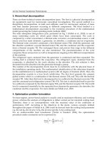
The maximum heat transfer rate of the MHP is increased as the operating temperature is
increased, which is similar to the medium-sized heat pipe. Fig. 1 shows the maximum heat
transfer rate according to the operating temperature variation for the curved rectangular MHP
fabricated through this study, which has 30% of working fluid compared with the total
volume. It is a characteristic of the MHP to have liquid block at the condenser during its
operation due to its small inner fluid flow space. The liquid block induces a decrease in its
performance since vapor cannot reach the condenser area, which is being occupied by the
liquid block, and thus cannot accomplish phase-change heat transfer in there. Thus, optimum
design of the working fluid amount is important to minimize the volume of the liquid block.
Fig. 2 shows the capillary radius distribution over axial direction of the MHP in conditions of
50 °C of operating temperature. The capillary radius can be calculated by equation (1):
12
11
cvl
cc
PPP
rr
(1)
Where r
c1
and r
c2
are the principal capillary radii of the meniscus. For the MHP designed in
this study, the capillary radius can be considered as r
c1
r
c(x)
and r
c2
since capillary
radius variation over axial direction occurred, but the capillary radius variation through
radial direction nearly not occurred. Fig. 3 shows the vapor and liquid pressure
distributions over axial direction of the MHP in the condition of 50 °C of operating
temperature.
30 40 50 60 70 80 90
0.0
0.2
0.4
0.6
0.8
1.0
1.2
1.4
Maximum Heat Transport Capacity (W)
Operating Temperature(
o
C)
Copper
Percent of Filling : 30%
Fig. 1. Maximum heat transport capacity according to operating temperatures
Heat Analysis and Thermodynamic Effects
274
0.000 0.005 0.010 0.015 0.020 0.025 0.030 0.035
0.0000
0.0001
0.0002
0.0003
0.0004
0.0005
0.0006
0.0007
Capillary radius (m)
Axial position x (m)
Fig. 2. Capillary radius variation over axial position
0.000 0.005 0.010 0.015 0.020 0.025 0.030 0.035
0
200
400
600
800
1000
1200
1400
Vapor
Liquid
Pressure difference (Pa)
Axial position x (m)
Fig. 3. Pressure distributions of vapor and liquid over axial position
3.2 Fabrication of the MHP
The size of the MHP developed in this study is smaller than that of the miniature heat pipe
with diameter of 3–4 mm. The MHP could be manufactured using current mechanical
technology of the simple manufacturing process. Therefore, this manufacturing process of
the MHP has a good productivity. In fact, the microstructures of the MHP may be
manufactured with etching process (Gerner, 1989), but such process has disadvantages in
terms of productivity and cost. The container of the MHP was manufactured with the
drawing process, and Fig. 1 shows its cross section. This MHP does not have additional
wick installed on the inner wall of the general heat pipe, but has sharp corners made with
structural deformation of its wall, which serves as wick.
Micro Capillary Pumped Loop for Electronic Cooling
275
The condensed liquid at the condenser of the MHP returns to the evaporator through the
capillary force of the liquid. It is important for the MHP to have sharp edges in the corners
to enable the working liquid to return from the condenser to the evaporator. The rectangular
MHP with curved sides (Fig. 4a) has advantages for thermal performance, such as larger
inner space for vapor flow and an additional corner for liquid path, than those of the
triangular MHP (Fig. 4b). Because the edge angle at the corner of the triangular MHP is
sharper than that of the rectangular MHP, the capillary force of the working fluid at the
triangular MHP is larger than that at the rectangular MHP. The specification of the MHP is
shown in Table 1.
(a) Curved rectangular (b) Curved triangular
Fig. 4. Cross section of MHP
Triangular MHP
Curved rectangular
MHP
Total length (mm) 50/100
Evaporator length 10 mm
Adiabatic section length 15 mm
Condenser length 25 mm
Working fluid Pure water
Fill ratio of working fluid 20%
Number of corners 3 4
Container material Oxygen-free copper
Container manufacturing
method
Drawing
Table 1. Experimental specification of MHP
FPMHPs with cross section of rectangular, modified rectangular, and triangular types were
newly developed in the present study. The container of the FPMHPs was manufactured by
the extrusion process, which could effectively form a sharp edge and significantly enhance
the productivity of FPMHPs. Moreover, mass production of FPMHPs is possible through
this method. The FPMHPs have three types of cross section – rectangular, modified
rectangular, and triangular. Fig. 5 shows the cross section of the FPMHPs; Table 2 presents
the dimensions of the FPMHPs.
Heat Analysis and Thermodynamic Effects
276
Thickness Width Total length
Rectangular type 2 mm 12 mm 50 mm
Modified rectangular type 1.5 mm 14 mm 50 mm
Triangular type 1.5 mm 12 mm 50 mm
Table 2. Dimensions of the FPMHPs
(a) Rectangular (b) Modified rectangular (c) Triangular
Fig. 5. Cross sections of the FPMHPs
3.3 Thermal performance of the MHP
The testing apparatus for the thermal performance of the MHP was composed of an MHP, a
vacuum chamber unit, a constant temperature bath for cooling the MHP, a data acquisition
system, and a DC power supplying unit, as shown in Fig. 6. The evaporator of the MHP was
heated using the electric resistance heater and DC power supply unit. The wire with 0.36
mm diameter and 10 Ω/m resistance per meter, as a heater, was wound around the copper
block with an interval of 0.5 mm for supplying the constant thermal load, which was
attached on the outer wall of the evaporator. The condenser of the MHP is cooled by the
water jacket with circulating water. Thermal grease (0.74 W/m °C) was filled between the
pipe wall and the water jacket in order to minimize the thermal contact resistance.
The vacuum chamber (10
-2
–10
-3
torr) made of acryl was used to minimize the heat loss to the
environment, as shown in Fig. 6. This vacuum chamber with a cylindrical body could be set
rotationally for the inclination angle tests. To measure the wall temperature of the MHP, K-
type thermocouples (Φ0.08 mm) were bonded by soldering at two points at the evaporator
wall, one point at the adiabatic section, and two points at the condenser. The locations of the
thermocouples are shown as X in Fig. 6 for the MHP with a total length of 50 mm. In the
case of the 100 mm length, the distance between the locations of the thermocouples would
be two times longer than that for the case of 50 mm length. The measured temperatures
were recorded by using the data acquisition system.
The MHP is made of oxygen-free copper with wall thickness of between 0.27 and 0.28 mm.
Pure water was used for the working fluid, which has relatively large surface tension and
latent heat characteristic from 30–160 °C of the operating temperature. The filling ratio of the
working fluid was 20% to the inner volume of the MHP. The liquid blocking region where
the vapor could not be reached may be created at the condenser, the end of the MHP with 1–
2 mm of equivalent diameter. The heat transfer by phase change of the working fluid could
not be accomplished in the liquid blocking region. The temperature at the end of the
condenser is 5–20 °C lower than that of the area adjacent to the condenser, and the heat
transfer rate of the MHP is decreased due to the liquid blocking. Therefore, the inactivated
amount of the working fluid due to liquid blocking should be considered at the design step
Micro Capillary Pumped Loop for Electronic Cooling
277
of the MHP for calculating the filling ratio of the working fluid. The generation mechanism
for the liquid blocking has not been reported in detail at any papers and still remained as an
undeveloped field.
The experimental test was performed to investigate the thermal performance of the MHP.
The operating temperature of the MHP identical with the temperature at the adiabatic
section of the MHP was considered for the four cases – 60 °C, 70 °C, 80 °C, and 90 °C. The
temperature and the amount of coolant circulating between the water jacket and the
constant temperature bath were controlled carefully to maintain the conditions of the
constant operating temperature of the MHP. The thermal load supplied to the MHP was
increased stepwise by 0.5 W from 0.5 W. The wall temperature of the MHP was recorded at
the steady state by each thermal load step. The measurement was stopped when the wall
temperature of the evaporator of the MHP rapidly increased due to dry-out. The wall
temperatures of the evaporator, the adiabatic section, and the condenser of the MHP were
averaged in each zone. This test was measured in the chamber with vacuum condition of 10-
2–10
-3
torr. The results of the present study included errors in measurement, i.e., the
tolerance in the heat supply (
0.05 V for voltage, 0.01 A for current) and that in the
temperature measurement (
0.1 °C). The performance testing apparatus of the FPMHP is
similar to that of the circular type MHP.
3.3 3.3 7.57.5 8.38.3
10 15 25
Evaporator
(Heater)
Adiabatic
Section
Condenser
(Water jacket)
50
Vacuum chamber(10-2~10-3torr)
[Unit: mm]
Vacuum
pump
Data logger
Personal
computer
Constant
Temp. Bath
Power Supply
A
V
X : Thermocouple location
3.3 8.3
Fig. 6. Experimental apparatus
A heat pipe can transport a large amount of heat with a slight temperature difference
between the evaporator and the condenser. In general, one of the test procedures to check
whether a non-condensable gas exists in the heat pipe or a heat pipe is operated well just
after the end of the manufacturing process is to measure the temperature difference between
the evaporator and the condenser. In that case, however, we should remember that each
heat pipe has a temperature difference as one’s own. In the case of a small-sized heat pipe
like the one in the present study, high-precision technologies are needed in the
manufacturing process because the presence of non-condensable gases or contaminants,
albeit small in amount, can be detrimental to the heat pipe performance.
Heat Analysis and Thermodynamic Effects
278
Fig. 7 shows the temperature distribution by the axial length of 50 mm. The tested MHP has
a curved triangular cross section and a 20% filling ratio to the inner total volume. The heat
was dissipated only at the condenser with the conduction heat transfer. The temperatures
were averaged over 60 seconds after steady state to reduce minor temperature fluctuation
error. As shown in Fig. 7, the wall temperatures of the MHP are increased as the thermal
load is increased. This means that the thermal equilibrium, which is the isothermal property
of the MHP from the evaporator to the condenser, is well accomplished. The temperature
differences between the evaporator and the condenser were 4.3
–
9.8 °C over the thermal
loads of 0.5–4 W. However, the temperature difference of 9.8 °C between the evaporator and
the condenser in the thermal load of 1 W is higher than that in other thermal loads. This is
because the amount of latent heat to be transported toward the condenser is small by
insufficient vaporization at the evaporator, and the thermal resistance is high by a relatively
thick liquid film under low thermal load near 1 W.
Fig. 8 shows the temperature distribution by the axial length at the operating temperature of
90 °C, which equals the temperature at the adiabatic section. The tested MHP is the same as
the one in Fig. 7. It is seen that the temperature difference between the evaporator and the
condenser is increased as the thermal load is increased at the constant operating
temperature of 90 °C. This can be explained by the fact that vapor flow velocity is increased
as the thermal load is increased. Therefore, the friction force on the vapor-liquid interface
and the pressure drop in the liquid flow are increased. Because the space for the vapor flow
in the MHP is narrower than that in the conventional heat pipe, the pressure drop caused by
the friction on the vapor-liquid interface may largely affect the MHP performance.
Fig. 9 shows the effect of the inclination angle on the thermal performance of the triangular
MHP. In the figure, the negative inclination angle indicates a top heating mode in which the
evaporator is located higher than the condenser, and conversely, the positive inclination angle
means a bottom heating mode in which the evaporator is located lower than the condenser. As
shown in Fig. 9, the effect of the inclination angle on the thermal performance is small. The
thermal performance of the MHP was almost the same for the tilting mode from the horizontal
mode to the top heating mode with –90 degrees. However, there was a decrease in the thermal
performance of the MHP as the inclination of the MHP was rotated from the bottom heating
mode to the top heating mode. That is, the thermal performance of the triangular MHP was
very stable in the bottom heating mode, and it is seen that the capillary force of the working
fluid was enough to flow from the condenser to the evaporator. The triangular MHP has the
limiting power of 4.51 W at the top heating mode of –90 degrees.
Fig. 10 shows the overall heat transfer coefficient according to the total length of the triangular
MHP. The considered lengths of the MHP were 50 mm and 100 mm. In the case of the MHP
with a small-sized equivalent diameter smaller than 2 mm, the effect of the pipe length on the
thermal performance of the MHP could be large. This is due to the fact that the pressure losses
by friction at the vapor-liquid interface and the capillary limitation for returning the
condensed liquid are significantly dominant as the pipe length is increased. As shown in Fig.
6, the thermal performance of the triangular MHP tends to be increased according to the
decrease in the pipe length. In the case of the triangular MHP, the overall heat transfer
coefficient was enhanced about 92% when the total length was decreased from 100 mm to 50
mm for the thermal load of 3 W. In the future, more detailed experimental results for the effect
of the pipe length on the thermal performance of the MHP will be studied.
A dry-out state occurs when the temperature at the evaporator’s lowest end for the bottom
heating mode is abruptly increased compared to other temperatures at the evaporator. The
Micro Capillary Pumped Loop for Electronic Cooling
279
thermal load just prior to the state in which heat transfer by phase change can no longer be
conducted due to a dry-out in the evaporator is defined as the heat transfer limit.
Fig. 11 shows the thermal resistances and heat transfer limits for the triangular MHP and the
rectangular MHP. The thermal resistance can be calculated by equation (2):
TT
ec
R
Q
(2)
Where T
e
and T
c
are the wall temperatures at the evaporator and the condenser of the MHP,
respectively, and Q(W) is a thermal load at the evaporator.
The tested MHP has a fill ratio of 20% to the internal total volume of the MHP. The
operating temperature is not constant, but increases as the thermal load is increased. The
heat dissipating at the condenser of the MHP was accomplished by circulating 20 °C water,
which was controlled by a constant temperature bath. As shown in Fig. 11, the heat transfer
limit of the triangular MHP is 1.6 times larger than that of the rectangular MHP. The heat
transfer limits were 4.5 W and 7 W for the rectangular MHP and the triangular MHP,
respectively. This is because the corners for the rectangular MHP are not developed sharply
compared to that for the triangular MHP and the capillary force needed for returning the
condensed liquid to the evaporator cannot be obtained sufficiently.
The property of the rectangular MHP having one additional corner than the triangular MHP
may make an advantage in its thermal performance. However, because a radius of curvature
at the corner is not sufficiently small to retain capillary pressure, the performance of the
rectangular MHP cannot be superior to that of the triangular MHP. The performance of the
MHP is largely restricted by the capillary limit.
The factor that mainly affects the capillary limit is the radius of curvature at the corner. The
radius of curvature
()r
is a function of a corner aperture angle
()
, a contact angle
()
,
and a location of the meniscus contact point in the corner
()
, as shown in equation (3).
Except for the two factors of
and
, which is constant as a heat pipe type, the operating
condition is the most important factor to the radius of curvature. The smaller the corner
aperture angle is, the smaller the radius of curvature is. Then, high capillary pumping
pressure and high maximum heat transfer limit can be obtained under this condition.
(, , )rf
(3)
The corner aperture angle of 60–70 degrees in the rectangular MHP of the present study is
larger than that of the angle 30–40 degrees in the analytical result of Zaghdoudi (Zaghdoudi
et al., 1997); therefore, the small radius of curvature cannot be obtained.
Fig. 12 presents the experimental thermal resistance and heat transfer limit of the triangular
MHP for various operating temperatures. The tested MHP has a fill ratio of 20% and was
performed for the various operating temperature of 60 °C, 70 °C, 80 °C, and 90 °C. As shown
in Fig. 8, the heat transfer limit is a function of the operating temperature; it increases as the
operating temperature is increased. The heat transfer limits were 6.18, 7.59, 8.01, and 10 W
for the operating temperatures of 60 °C, 70 °C, 80 °C, and 90 °C, respectively.
Fig. 13 presents the experimental results of the present study and those of Moon (Moon et al.,
1999) for the heat transfer limit. The MHP tested in Moon et al. had a curved triangular cross
section and a stainless steel as container material. Pure water was used as working fluid. As
shown in Fig. 13, the heat transfer limit of the present study is 1.7–2.1 times larger than that of
Heat Analysis and Thermodynamic Effects
280
Moon et al. over the operating temperature of 60–80 °C. This result shows that large capillary
limit was obtained in the present study compared to that in Moon (Moon et al., 1999). High
productivity and simple manufacturing process were considered, and enhanced performance
was obtained compared to that of Moon et al. for the future applications.
Figs. 14 and 15 show the performance test results of temperature distributions along with
the length of the FPMHP. In both figures, it can be seen that the temperatures of the
condenser instantly follow the temperature of the evaporator for overall thermal loads. This
phenomenon means that the FPMHPs have good constant temperature characteristics as a
heat pipe. The temperature differences between the evaporator and the condenser are 2.5–
6.4 °C for the FPMHP with fill ratio of 25% and 2.2–11.9 °C for the one with fill ratio of 15%,
respectively.
When the temperature of the evaporator was considered within the temperature of 120 °C,
Table 3 shows the heat transfer rate of the FPMHP with fill ratio of 20%. In the table, the
heat transfer rate of the rectangular FPMHP is higher than that of other FPMHPs. The heat
transfer rate of the modified rectangular FPMHP is as high as that of the rectangular
FPMHP is due to the capillary force of the former being higher than that of the latter.
Meanwhile, the heat transfer rate of the triangular FPMHP is lower than that of other
FPMHPs due to its characteristic of having small space for vapor flow.
0 1020304050
30
45
60
75
90
105
120
135
150
Condenser
Adiabatic
section
Evaporator
Wall Temperature (
o
C)
Axial Length (mm)
Q
in
=0.5W
Q
in
=1W
Q
in
=2W
Q
in
=3W
Q
in
=4W
Fig. 7. Wall temperature distribution along the longitudinal axis by thermal loads
0 1020304050
84
87
90
93
96
99
102
Condenser
Adiabatic
section
Evaporator
Wall Temperature (
o
C)
Axial Length (mm)
Q
in
=4W
Q
in
=5W
Q
in
=6W
Q
in
=7W
Q
in
=8W
Q
in
=9W
Fig. 8. Wall temperature distribution along the longitudinal axis of the MHP at Tv = 90 °C
Micro Capillary Pumped Loop for Electronic Cooling
281
-90 -45 0 45 90
0
5
10
15
20
25
Heat Transfer Limit (W)
Inclination Angle (degree)
Curved triangular MHP
Fill ratio of 20%
Fig. 9. Thermal performance by inclination angle
01234
0
200
400
600
800
1000
1200
1400
Overall Heat Transfer Coefficient (W/m
2o
C)
Input Power (W)
L
total
=100mm
L
total
=50mm
Fig. 10. Overall heat transfer coefficient by total length
012345678
0
5
10
15
20
25
Thermal Resistance (
o
C/W)
Input Power (W)
Curved rectangular MHP
Curved triangular MHP
Fig. 11. Performance comparison by cross-section type
Heat Analysis and Thermodynamic Effects
282
024681012
0
2
4
6
8
10
Dryout points
Thermal Resistance (
o
C/W)
Input Power (W)
Tv=60
o
C
Tv=70
o
C
Tv=80
o
C
Tv=90
o
C
Fig. 12. Thermal performance by the operating temperature
50 60 70 80 90
2
4
6
8
10
12
Heat Transfer Limit (W)
Operating Temperature (
o
C)
Experimental data(Present study)
Experimental data(Moon et al,1999)
Fig. 13. Experimental results comparison between the present study and Moon et al.
0 1020304050
30
45
60
75
90
105
120
135
Condenser
Adi abatic
section
Evaporator
Wall Temperature,
o
C
Axial Length, mm
Q
in
=0.5W
Q
in
=1W
Q
in
=2W
Q
in
=3W
Fig. 14. Temperature distributions along FPMHP with fill ratio of 25% with the axial length
for rectangular
Micro Capillary Pumped Loop for Electronic Cooling
283
0 1020304050
40
50
60
70
80
90
100
Condenser
Adiabatic
section
Evaporator
Wall temperature,
o
C
Axial Length, mm
Q
in
=0.5W
Q
in
=1.0W
Q
in
=1.5W
Fig. 15. Temperature distributions along with the axial length for rectangular FPMHP with
fill ratio of 15%
Heat transfer rate
Rectangular 13.66 W
Modified rectangular 13 W
Triangular 8 W
Table 3. Heat transfer rate of each FPMHP with fill ratio of 20%
3.4 Why micro CPL is needed in the future
Vapor and liquid have counter flow pattern in the heat pipe. Therefore, pressure drop on
the vapor-liquid interface is created, which then leads to a decrease in the heat transfer
performance of the heat pipe. Fig. 16 shows the effect of shear force on the vapor-liquid
interface to the maximum heat transport capacity. The result shows that the case wherein no
shear force is considered is about twice the maximum heat transport capacity of that which
considers shear force. From the result, we can realize that the shear force on the vapor-liquid
interface significantly affects the performance of the small-sized heat pipe. The micro CPL
could be considered as an alternative solution. It has separated vapor and liquid flow path
compared to the MHP. Therefore, when there is no shear force on the vapor-liquid interface,
then pressure drop by shear force cannot occur. However, the successful fabrication of
small-sized micro CPL with flat plate shape shows that a normal operating characteristic is
not easy.
4. Micro CPL
4.1 Design of the micro CPL
Considering the tendency of portable electronic and communication devices to become
thinner and thinner, flat plate type cooling devices offer great convenience to be applied to
such devices compared with circular type cooling devices. In the present, the flat heat pipe
pressed from a circular shape has been widely used in notebook PCs, sub-notebook PCs,