Human Musculoskeletal Biomechanics Part 1 pdf
Bạn đang xem bản rút gọn của tài liệu. Xem và tải ngay bản đầy đủ của tài liệu tại đây (872.68 KB, 20 trang )
HUMAN
MUSCULOSKELETAL
BIOMECHANICS
Edited by Tarun Goswami
Human Musculoskeletal Biomechanics
Edited by Tarun Goswami
Published by InTech
Janeza Trdine 9, 51000 Rijeka, Croatia
Copyright © 2011 InTech
All chapters are Open Access articles distributed under the Creative Commons
Non Commercial Share Alike Attribution 3.0 license, which permits to copy,
distribute, transmit, and adapt the work in any medium, so long as the original
work is properly cited. After this work has been published by InTech, authors
have the right to republish it, in whole or part, in any publication of which they
are the author, and to make other personal use of the work. Any republication,
referencing or personal use of the work must explicitly identify the original source.
Statements and opinions expressed in the chapters are these of the individual contributors
and not necessarily those of the editors or publisher. No responsibility is accepted
for the accuracy of information contained in the published articles. The publisher
assumes no responsibility for any damage or injury to persons or property arising out
of the use of any materials, instructions, methods or ideas contained in the book.
Publishing Process Manager Iva Simcic
Technical Editor Teodora Smiljanic
Cover Designer Jan Hyrat
Image Copyright Stephen Coburn, 2010. Used under license from Shutterstock.com
First published August, 2011
Printed in Croatia
A free online edition of this book is available at www.intechopen.com
Additional hard copies can be obtained from
Human Musculoskeletal Biomechanics, Edited by Tarun Goswami
p. cm.
ISBN 978-953-307-638-6
free online editions of InTech
Books and Journals can be found at
www.intechopen.com
Contents
Preface IX
Part 1 Motion Preservation 1
Chapter 1 A Task-Level Biomechanical Framework
for Motion Analysis and Control Synthesis 3
Vincent De Sapio and Richard Chen
Chapter 2 European Braces
for Conservative Scoliosis Treatment 29
Theodoros B. Grivas
Chapter 3 Motion Preservation and Shock
Absorbing in Cervical and Lumbar Spine:
A New Device for Anterior Cervical Arthroplasty,
for Anterior or Posterior Lumbar Arthroplasty 49
Giuseppe Maida
Part 2 Musculoskeletal Biomechanics 59
Chapter 4 Biomechanical Characteristics of the Bone 61
Antonia Dalla Pria Bankoff
Chapter 5 Biomechanical Studies
on Hand Function in Rehabilitation 87
Sofia Brorsson
Chapter 6 Cervical Spine Anthropometric and
Finite Element Biomechanical Analysis 107
Susan Hueston, Mbulelo Makola,
Isaac Mabe and Tarun Goswami
Chapter 7 Biomechanics of the Temporomandibular Joint 159
Shirish M. Ingawalé and Tarun Goswami
VI Contents
Part 3 Nano Behavior 183
Chapter 8 Design and Analysis of Key Components
in the Nanoindentation and Scratch Test Device 185
Hongwei Zhao, Hu Huang, Jiabin Ji and Zhichao Ma
Part 4 Vascular Biomechanics 209
Chapter 9 Elements of Vascular Mechanics 211
Gyorgy L Nadasy
Preface
The field of biomechanics has been evolving from the ancient Greeks times. Recent
publications and research in biomechanics sky rocketed as the field of traditional
biomechanics is creating new opportunities in diagnostics, therapy, rehabilitation,
motion preservation, kinesiology, total joint replacement, biomechanics of living
systems at small scale, and other areas.
Biomechanics now encompasses a range of fields. The book on Human Musculoskeletal
Biomechanics is a broad topic and may provide the platform for newer text and editions
as the research evolves and new results obtained. In the current form, the book covers
four areas: 1) motion preservation, which will be useful in designing functional braces
for different skeletal areas used in therapy and/or rehabilitation, 2) musculoskeletal
biomechanics, which includes soft and hard tissue and their behavior under the actions
of forces, motion, strain and modeling them analytically and experimentally, 3) nano-
behavior, is another area which is developing where mechanical properties of living
systems are determined that will be useful in developing treatment methods and
understanding the small living systems such as viruses, and 4) vascular biomechanics, a
new area that will also develop in the future with surgery.
Therefore, the book presents information on the four sections, in a concise format.
Based on these sections, new courses may be developed at graduate level or some of
the concepts used to teach undergraduate students in biomedical engineering. Since
the book will be available on open access, its use will be free to students, and to
introduce this topic as a new course, if desired. The four sections presented in this
book will continue to challenge both the researchers and students in the future and
therefore, creation of new knowledge.
Dr. Tarun Goswami
D.Sc. Equity Advisor - College of Engineering and Computer Science;
Founding Director - Device Development Center;
Director - Damage Tolerance and Probabilisitic Life Prediction of Materials Center;
Focus Area Chair - Ph.D. in Engineering - Medical and Biological Systems;
Associate Professor of Biomedical, Industrial, and Human Factors Engineering,
Wright State University;
Associate Professor, Department of Orthopaedic Surgery, Sports Medicine & Rehabilitation
USA
Part 1
Motion Preservation
Vincent De Sapio and Richard Chen
Sandia National Laboratories
*
USA
1. Introduction
The behavioral richness exhibited in natural human motion results from the complex interplay
of biomechanical and neurological factors. The biomechanical factors involve the kinematics
and dynamics of the musculoskeletal system while the neurological factors involve the
sensorimotor integration performed by the central nervous system (CNS). An adequate
understanding of these factors is a prerequisite to understanding the overall effect on human
motion as well as providing a means for synthesizing human motion.
The fields of neuroscience, biomechanics, robotics, and computer graphics provide
motivation, as well as tools, for understanding human motion. In neuroscience, fundamental
scientific understanding drives the motivation to understand human motion, whereas,
in biomechanics, clinical applications often form the driving motivation. These clinical
applications involve the use of movement analysis and simulation tools to help direct patient
rehabilitation as well as predict the effects of surgery on movement.
In addition to the clinical desire to analyze movement there has been an emerging desire
in recent years to synthetically generate human-like motion in both simulated and physical
settings. In computer graphics this desire is directed toward autonomously generating
realistic motion for virtual actors. The intent is to direct these virtual actors using high-level
goal directed commands for which low-level motion control is automatically generated.
Motivated by similar desires, the robotics community seeks a high-level control framework
for robotic systems. With the recent advent of complex humanoid robots this challenge has
grown more demanding. Consistent with their anthropomorphic design, humanoid robots are
intended to operate in a human-like manner within man-made environments and to promote
interaction with their biological counterparts. To achieve this, common control strategies have
involved generating joint space trajectories or learning specific motions, but these approaches
require extensive motion planning computations and do not generalize well to related tasks.
1.1 Human motion control
The basic constituents of the human motor system include the biomechanical plant and the
CNS. A high-level block diagram, sufficient for our present purposes, is depicted in Fig.
1. Based on some specified task the CNS performs motor planning which culminates in
low-level control issued as a motor command to the biomechanical plant. This motor planning
*
Sandia National Laboratories is a multi-program laboratory managed and operated by Sandia
Corporation, a wholly owned subsidiary of Lockheed Martin Corporation, for the U.S. Department of
Energy’s National Nuclear Security Administration under contract DE-AC04-94AL85000.
A Task-Level Biomechanical Framework for
Motion Analysis and Control Synthesis
1
2 Will-be-set-by-IN-TECH
and control occurs based on the integration of sensory information from proprioceptors
distributed throughout the musculoskeletal system. Some knowledge of the biomechanical
plant is also assumed to be encoded in the CNS.
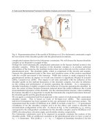
Fig. 1. Motor control involves the task-driven action of the central nervous system (CNS) on
the biomechanical plant. Given proprioceptive information the CNS performs motor
planning which results in the issuance of motor commands.
While the biomechanical plant can be decomposed and understood in reasonable detail the
processes of the CNS are understood more vaguely. As a consequence, while Fig. 1 provides
a conceptual framework, with regard to the CNS it lacks enough precision to be useful as a
functional model. For this reason it is appropriate to consider some more basic analogs. To
this end we will consider the most basic analog which is still useful, that of a joint space model,
followed by task/posture analogs.
1.2 Joint space motion control
Joint space control is the earliest and still most common form of feedback control in robotic
systems. In this scheme a task is specified in some natural coordinate system associated with
the robot and environment. Based on a knowledge of the robot kinematics, the robot controller
performs inverse kinematic computations to arrive at a posture or trajectory in terms of joint
angles. The joint command is issued to the servo motors which execute the motion.
While this method of controlling a robot is effective it requires the computation of inverse
kinematics. Additionally, it does not make use of any knowledge of the robot’s dynamics.
The method of computed torque is an enhancement of the basic joint space control approach
in which the controller does make use of the robot’s dynamics. However, the control is still
encoded in joint space rather than a more natural task space description. As an analog to the
human motor system this joint space encoding may constitute a deficiency since a number
of studies, Buneo et al. (2002); Sabes (2000); Scholz & Schöner (1999); Shenoy et al. (2003),
suggest a task-oriented spatial encoding of planning and control. Rather than using inverse
kinematic transformations this task-oriented encoding is accomplished through visumotor
transformations from retinal coordinates to hand- or body-centered spatial coordinates.
1.3 Task/posture motion control
Motivated by evidence for a task-oriented spatial encoding of motion by the CNS we
now consider a task/posture control model. This is depicted in Fig. 2 and represents a
generalization beyond a strict joint space motor control model. In this case the control is
encoded in the same native space in which the task is expressed. This obviates the need for
inverse kinematics to convert the task description into a joint space description. The dynamics
of the robot plant are expressed in task space with a complementary description of the posture
4
Human Musculoskeletal Biomechanics
A Task-level Biomechanical Framework for Motion Analysis and Control Synthesis 3
(see Fig. 3). The controller exploits this decomposed structure to yield separate task and
posture control terms. As such, the posture term can be chosen to minimize some criterion,
consistent with the execution of the task. The motor command can then be issued in the
appropriate actuator space (e.g., motor torques).
Fig. 2. Task space motion control model where the dynamics are decomposed into
complementary task and posture spaces. The posture control can be chosen using an
auxiliary criterion which can be optimized consistent with the execution of the task (image
courtesy of NASA).
As alluded to earlier this task/posture model represents a more general abstraction than the
joint space model, and may be more suitable for purposes of modeling and understanding
human motor control. The notions of task and posture are directly applicable to human
motion control and, as we shall see, can be specifically interpreted in terms of physiological
criteria.
1.4 Task/posture approach for biomechanical systems
Up to this point we have considered robotic control models as a means of addressing human
motor control. In a more general sense the challenge of synthesizing low-level human motion
control from high-level commands can be addressed by integrating approaches from the
Fig. 3. A task description with complementary task consistent postures. Redundancy with
respect to task introduces task dynamics as well as posture dynamics.
5
A Task-Level Biomechanical Framework for Motion Analysis and Control Synthesis
4 Will-be-set-by-IN-TECH
biomechanics and robotics communities. The biomechanics community has investigated
the phenomenon of neuromuscular dynamics and control through the use of computational
muscle models. This characterization allows for the description of muscle strength limitations,
activation delays, and overall muscle contraction dynamics. Properly accounting for these
characteristics is critical to authentically simulating human motion. In a complementary
manner, the robotics community has investigated the task-level feedback control of robots
using the operational space approach. This approach recasts the dynamics of the robotic
system into a relevant task space description. This provides a natural mechanism for
specifying high-level motion commands that can be executed using feedback control.
Fig. 4. Task/posture motion control model for biomechanical systems. In addition to task
control, neuromuscular criteria are used to control the posture by minimizing neuromuscular
cost, consistent with the execution of the task.
Fig. 4 depicts a task/posture model of motor control which integrates robotic and
biomechanical approaches. In this model the CNS is seen to affect motor control using
task/posture decomposition. While the control is task-driven the task consistent postures
are driven by neuromuscular criteria. In other words, while the CNS issues motor commands
to achieve some task it is assumed that this is being done in a way that minimizes some
neuromuscular cost (subject to the task requirements). While the precise nature of what, if
anything, is being minimized by the CNS is difficult to directly infer, computational muscle
models can be used to evaluate particular hypothetical effort criteria. Predicted postural
behavior associated with minimizing these criteria can then be compared with actual postures
from subject trials to validate the applicability of the criteria.
Through the combined utilization of task-level constrained motion strategies and
computational muscle models this chapter addresses motion control with application to
human motion synthesis. A coherent framework is presented for the management of motion
tasks, physical constraints, and neuromuscular criteria. The subsequent sections will address
the constituent elements of this framework and will be divided into (i) task-based modeling
and analysis and (ii) posture-based modeling and analysis.
2. Task-based modeling and analysis of biomechanical systems
In this section we present a task-based formulation for application to biomechanical systems.
In the overall framework this addresses the highlighted element of Fig. 5. The focus is on task
control in the presence of constraints.
6
Human Musculoskeletal Biomechanics
A Task-level Biomechanical Framework for Motion Analysis and Control Synthesis 5
*
Fig. 5. Task/posture motion control model for biomechanical systems highlighting task
control in the presence of constraints. In this chapter the human shoulder complex will be
investigated using this approach.
2.1 Configuration space dynamics
The equations of motion for a multibody system that is unconstrained with respect to
configuration space can be expressed by the Euler-Lagrange equations,
d
dt
∂
L
∂ ˙q
−
∂L
∂q
= τ ,(1)
where
L = L(q,˙q) is the Lagrangian of the system, q ∈ R
n
is the vector of generalized
coordinates, and τ
∈ R
n
is the vector of generalized actuator forces (torques). In standard
matrix form the equations of motion can be expressed as,
M
(q) ¨q + b(q,˙q)+f (q,˙q)=B(q,˙q)
T
u,(2)
where u
∈ R
k
is the vector of control inputs, B( q,˙q)
T
∈ R
n×k
is the matrix mapping control
inputs to generalized actuator forces, M
(q) ∈ R
n×n
is the configuration space mass matrix,
b
(q,˙q) ∈ R
n
is the vector of centrifugal and Coriolis terms, and f (q,˙q) ∈ R
n
is the vector
of generalized applied forces. We will often use a modified and more specialized form of (2)
commoninrobotics,
M
(q) ¨q + b(q,˙q)+g(q)=τ ,(3)
where g
(q) ∈ R
n
is the vector of gravity terms. The form of (3) assumes that the generalized
actuator forces can be directly interpreted as control inputs; that is, τ
= B
T
u = u, i.e.,
B
T
= 1. Additionally, the generalized applied forces are assumed to be restricted to gravity
terms; that is, f
(q,˙q)=g(q).
We now introduce a set of m
C
holonomic and scleronomic constraint equations, φ( q)=0 ∈
R
m
C
, that are satisfied on a p = n − m
C
dimensional manifold, Q
p
, in configuration space,
Q
= R
n
. The gradient of φ yields the constraint matrix,
Φ
(q)=
∂φ
∂q
∈ R
m
C
×n
.(4)
Adjoining the constraints to (3) by introducing a set of constraint forces yields the dynamic
equation in the familiar multiplier form,
M ¨q
+ b + g − Φ
T
λ = τ,(5)
7
A Task-Level Biomechanical Framework for Motion Analysis and Control Synthesis
6 Will-be-set-by-IN-TECH
subject to,
Φ ¨q
+
˙
Φ ˙q
= 0 (φ = 0, Φ ˙q = 0),(6)
where λ is a vector of unknown Lagrange multipliers.
2.2 Task space dynamics and control
In the previous section we considered configuration space descriptions of the dynamics of
constrained multibody systems. Our objective is to reformulate these descriptions in the
context of task space, Khatib (1987); Khatib (1995). This will provide the foundation for
constrained task-level control to be discussed in the next section.
Given a branching chain system and defining a set of m task, or operational space, coordinates,
x
∈ R
m
we define the task Jacobian as,
J
(q)=
∂x
∂q
∈ R
m×n
.(7)
The generalized force (or control torque) in (3) can then composed as J
T
f ,wheref ∈ R
m
is the task, or operational space, force. In the redundant case an additional term needs to
complement the task term in order to realize any arbitrary generalized force. We will refer
to this term as the null space term and it can be composed as N
T
τ
o
,whereτ
o
is an arbitrary
generalized force and N
(q)
T
∈ R
n×n
is the null space projection matrix. We then have the
following set of unconstrained task, or operational space, equations of motion, Khatib (1987),
Λ
(q) ¨x + μ(q,˙q)+p(q)=f ,(8)
where Λ
(q) ∈ R
m×m
is the operational space mass matrix, μ(q,˙q) ∈ R
m
is the operational
space centrifugal and Coriolis force vector, and p
(q) ∈ R
m
is the operational space gravity
vector. These terms are given by,
Λ
(q)=(JM
−1
J
T
)
−1
,(9)
μ
(q,˙q)=ΛJM
−1
b − Λ
˙
J ˙q, (10)
p
(q)=ΛJM
−1
g, (11)
N
(q)
T
= 1 − J
T
ΛJM
−1
. (12)
Thus, the overall dynamics of our multibody system, given by,
M ¨q
+ b + g = J
T
f + N
T
τ
o
= τ , (13)
can be mapped into task space,
M ¨q
+ b + g = τ
¯
J
T
→
f = Λ ¨x + μ + p, (14)
where
¯
J is the dynamically consistent inverse of the task Jacobian,
¯
J
= M
−1
J
T
Λ. (15)
In a complementary manner the overall dynamics can be mapped into the task consistent null
space (or self-motion space) using N
T
.
8
Human Musculoskeletal Biomechanics
A Task-level Biomechanical Framework for Motion Analysis and Control Synthesis 7
The overall dynamics can be expressed as,
J
T
(Λ ¨x + μ + p)+N
T
τ
o
= τ . (16)
A controller employing (8) would be assumed to have imperfect knowledge of the system.
Therefore, (8) should reflect estimates for the inertial and gravitational terms. Additionally,
a control law needs to be incorporated. To this end we replace ¨x in (8) with the input of the
decoupled system, Khatib (1995) f
, to yield the dynamic compensation equation,
f
=
Λf
+ μ + p, (17)
where the . represents estimates of the dynamic properties. Thus our control torque is,
τ
= J
T
(
Λf
+ μ + p)+
N
T
τ
o
. (18)
Any suitable control law can be chosen to serve as input of the decoupled system. In
particular, we can choose a linear proportional-derivative (PD) control law of the form,
f
= K
p
(x
d
− x)+K
v
( ˙x
d
− ˙x)+¨x
d
, (19)
where x
d
are reference values for the task coordinates and K
p
and K
v
are gain matrices.
As we introduced a set of m
C
holonomic and scleronomic constraint equations to the
configuration space dynamics we can do the same for the task space dynamics. Mapping
(5) and (6) into an appropriate task/constraint space yields, De Sapio et al. (2006),
Λ ¨x
+ μ + p −
¯
J
T
Φ
T
(α + ρ)=
¯
J
T
Θ
T
τ . (20)
The term α
(q,˙q) ∈ R
m
C
is the vector of centrifugal and Coriolis forces projected at the
constraint, and ρ
(q) ∈ R
m
C
is the vector of gravity forces projected at the constraint. These
terms are given by,
α
(q,˙q)=HΦM
−1
b − H
˙
Φ ˙q, (21)
ρ
(q)=HΦM
−1
g, (22)
where H
(q) ∈ R
m
C
×m
C
is the constraint space mass matrix which reflects the system inertia
projected at the constraint,
H
(q)=(ΦM
−1
Φ
T
)
−1
. (23)
The constraint null space projection matrix, Θ
(q)
T
∈ R
n×n
,isgivenby,
Θ
(q)
T
= 1 − Φ
T
¯
Φ
T
, (24)
where,
¯
Φ, is the dynamically consistent inverse of Φ,
¯
Φ
= M
−1
Φ
T
H. (25)
The control equation can be expressed as,
¯
J
T
Θ
T
τ =
Λf
+ μ + p −
¯
J
T
Φ
T
( α + ρ), (26)
where the linear control law of (19) can be used.
9
A Task-Level Biomechanical Framework for Motion Analysis and Control Synthesis
8 Will-be-set-by-IN-TECH
It is noted that (20) does not expose the constraint forces (Lagrange multipliers). An alternate
form of the constrained task space dynamics is, De Sapio & Park (2010); De Sapio (2011),
Θ
T
J
T
(Λ
c
¨x + μ
c
+ p
c
)+Φ
T
(α + ρ)+N
T
c
τ
o
− Φ
T
λ = τ. (27)
The term Λ
c
(q) ∈ R
m×m
is the task/constraint space mass matrix, μ
c
(q,˙q) ∈ R
m
is the
task/constraint space centrifugal and Coriolis force vector, p
c
(q) ∈ R
m
is the task/constraint
space gravity vector, and N
c
(q)
T
∈ R
n×n
is the task/constraint null space projection matrix.
These terms are given by,
Λ
c
(q)=(JM
−1
Θ
T
J
T
)
−1
, (28)
μ
c
(q,˙q)=Λ
c
JM
−1
Θ
T
b − Λ
c
(
˙
J
− JM
−1
Φ
T
H
˙
Φ) ˙q, (29)
p
c
(q)=Λ
c
JM
−1
Θ
T
g, (30)
N
c
(q)
T
= Θ
T
(1 − J
T
Λ
c
JΘM
−1
). (31)
Equation (27) expresses the control torque as a function of the task accelerations, ¨x,the
kinematic and dynamic properties, and the constraint forces, λ. The control equation can
be expressed as,
τ
+ Φ
T
λ =
Θ
T
J
T
(
Λ
c
f
+ μ
c
+ p
c
)+Φ
T
( α + ρ)+
N
T
c
τ
o
, (32)
where the linear control law of (19) can be used. These equations need to be complemented
by a passivity condition on any unactuated joints,
S
p
τ = 0, (33)
where S
p
∈ R
(n−k)×n
is a selection matrix that identifies the passive (unactuated) joints.
We can express (32) as,
τ
+ Φ
T
S
T
u
λ
u
=
Θ
T
J
T
(
Λ
c
f
+ μ
c
+ p
c
)+Φ
T
( α + ρ − S
T
c
λ
c
d
)+
N
T
c
τ
o
, (34)
where S
c
∈ R
(k−p)×m
C
is a selection matrix used to select the controlled constraint forces and
S
u
∈ R
(n−k)×m
C
is a selection matrix used to select the uncontrolled constraint forces. The
terms λ
c
d
and λ
u
are the vectors of controlled and uncontrolled constraint forces, respectively,
selected out of the full vector of constraint forces. The term λ
c
d
is specified as part of the
control reference, along with x
d
, ˙x
d
,and¨x
d
. We can solve for the control torque,
τ
=(1 − Φ
T
S
T
u
(S
p
Φ
T
S
T
u
)
−1
S
p
)h(q,˙q), (35)
where,
h
(q,˙q)
Θ
T
J
T
(
Λ
c
f
+ μ
c
+ p
c
)+Φ
T
( α + ρ − S
T
c
λ
c
d
)+
N
T
c
τ
o
. (36)
2.3 Task-level control applied to biomechanical Systems
In this section we apply the task-level control formulation, presented in the previous section,
to a biomechanical subsystem. This formulation possesses particular efficacy in addressing
10
Human Musculoskeletal Biomechanics