Indoor and Outdoor Air Pollution Part 10 ppt
Bạn đang xem bản rút gọn của tài liệu. Xem và tải ngay bản đầy đủ của tài liệu tại đây (2.13 MB, 10 trang )
Correlation of Professional Performance to Acceptable IAQ in Critical Care Medical Facilities
81
2. Contributing causes to a defective building
The following factors have played a part in our findings in addition to inadequate budgets
and overly optimistic building programs.
2.1 The economy v. mentoring system
Most design professions require an advanced or professional degree at a recognized
institution of higher learning. Internship requirements follow a professional education
(three years for aspiring architects and engineers). Finally, a professional exam issued by a
state is required for licensure. In the past, aspiring design professionals had the opportunity
to sit by the side of the “master” and learn the craft of designing a building and its systems.
Inflation and the demands of a super-heated economy have changed this scenario. Today,
when everything is available instantly, and time is money, the opportunity to engage and
learn from the “master” is long gone and this void is worsened by;
2.2 Computers v. knowledge
Although the use of Computer Aided Design systems (CAD) is now universal and certainly
can be a great asset to the design team, detail “libraries” can subvert the process of thinking
through how things fit together and perform within an overall system. The authors have
reviewed construction documents that contain pages and pages of details with the notation
that they “may not be a part of this project”.
4
This language is completely unacceptable, but
does support the notion that some architects either do not understand the importance of a
clear set of construction documents, or are yielding to time constraints.
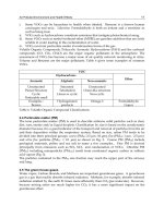
2.3 Specialization itself
The myriad complexities of the typical critical care medical facility require a significant
amount of time in coordination with the end user and various disciplines required to ensure
the efficient functioning of this facility. For example, Building codes, accessibility standards,
and energy requirements must be addressed, as well as state health codes and the Center for
Disease Control (“CDC”) infectious disease control guidelines (CDC 2003). The authors’
review determined 1) the architectural design team was so focused on the functional
complexities that the fundamental task of ensuring that the building envelop would keep
out the elements was overlooked; 2) the construction documents and or industry standards
were not followed resulting in system failures; 3) the fundamentals of mechanical design for
the climatic location of the building and or operating standards were not appropriately
applied, and 4) the environmental systems were poorly installed, were not sufficiently
commissioned, and did not perform to minimum standards.
3. Case studies
The following case studies involved architects that were ostensibly seasoned and who had
specialized in the design of critical care medical facilities.
3
Currently unknown as to unintended consequences “Green” or “Sustainable Buildings” associated
with the U.S. Green Building Council’s Leed Certifications have recently been developed to address
energy issues and diminishing resources.
4
Found on the construction document for a multi-million dollar renovation of a high school in Texas,
circa 2005.
Indoor and Outdoor Air Pollution
82
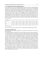
3.1 Case study 1(“CS 1”)
This single story surgery center was constructed in 2004. It was 19,000 square feet and
constructed under a design/build delivery system.
5
Its exterior was composed of applied
stone veneer and an Exterior Finish Insulation System (EFIS). The hospital staff noticed mold
growth, wild swings in temperature, and wet indoor environment almost from the day they
occupied the building. An investigation ensued and determined that defects discovered
associated with the shell of the building, or envelope, was a major contributor, along with the
HVAC, to the difficulties they were encountering. Site drainage violated code and held water
against the building. It is fundamental to the proper placement of a building to locate it on the
site both vertically and horizontally. The horizontal aspect of the placement is guided by local
zoning codes. Vertical placement is guided by common sense, water should drain away from
a building and thus, downhill. Building codes have language to ensure that the common sense
approach is met. For example the building code reads: “The ground immediately adjacent to
the foundation shall be sloped away from the building at a slope of not less than one unit
vertical in 20 units horizontal (5-percent slope) for a minimum distance of 10 feet (3048 mm)
measured perpendicular to the face of the wall or an approved alternate method of diverting
water away from the foundation shall be used.” (International Building Code [IBC] Chapter
18: Soils and Foundation, 1803.3 Site Grading, 2000).
Compounding this hospital’s flawed start were flashings that were either missing or
misapplied. It follows that if it is important to drain water away from a building, it is just as
important to drain it out of the exterior wall systems. To accomplish this, drainage planes,
flashings and weeps should be well known by architects, engineers and constructors and
they are well documented in industry and professional publications. Codes, again, have
language to ensure these fundamentals are met. For example, the 2000 Edition of the
International Building Code reads: “Exterior walls shall provide the building with a
weather-resistant exterior wall envelope. The exterior wall envelope shall include flashing,
as described in Section 1405.3. The exterior wall envelope shall be designed and constructed
in such a manner as to prevent the accumulation of water within the wall assembly by
providing a water-resistive barrier behind the exterior veneer, as described in Section 1402.2
and a means for draining water that enters the assembly to the exterior of the veneer, unless
it is determined that penetration of water behind the veneer shall not be detrimental to the
building performance. Protection against condensation in the exterior wall assemble shall be
provide in accordance with the International Energy Conservation Code” (IBC, Exterior
Walls, Section 1403.2, Weather Protection, 2000).
When combined with the fact that water stands against the building, the base flashing not
only did not allow water to drain it instead reversed the flow of water such that outside
water entered the building. The end result was mold growth along the entire perimeter of
the building.
Doors, windows, and louvers all penetrate the walls, thus flashings are also used to divert
water to the exterior of a building. Codes (IBC Section 1405.3; Flashing., 2003) and
manufacturer’s details leave no doubt that the flashing of openings is a requirement, and
that information as to materials and methods are readily available. The consequence of
ignorance or neglect is water pouring into the building.
5
Design/Build is where the builder contracts with the owner to design and construct a project as
opposed to the traditional method where the owner hires an architect to design and a builder to
construct.
Correlation of Professional Performance to Acceptable IAQ in Critical Care Medical Facilities
83
Fig. 1. Site drainage violated code and, held water against the building.
Fig. 2. The copper-coated base flashing at the applied masonry veneer wall terminated
below grade and therefore did not allow for the water to drain.
Although flashings are addressed in building codes (IBC Section 1405.3; Flashing., 2003), it is
more perplexing as there were a myriad of opportunities for the CS 1 architect and
contractor to determine the appropriate method to terminate the exterior wall. Industry
organizations, product manufacturers and associations all have literature readily available
Indoor and Outdoor Air Pollution
84
on the internet.
6
This information is not only available but details and specifications can be
downloaded for use by the architect.
7
Furthermore the General Conditions of the Contract
for Construction Standard Form of Agreement A201 [American Institute of Architects (AIA),
1997] delineate processes to resolve conflicts. Above the veneered surface of the CS 1
exterior wall, and continuing to the roof was EFIS. EFIS has become widely popular as a
light weight, inexpensive system that has the appearance of stucco. Early on, problems arose
regarding this system’s propensity to hold water between the insulation board and the
exterior sheathing which led to mold growth and eventually, numerous law suits.
8
The
industry responded by improving the product and producing numerous details and
installation procedures, all of which can be accessed via the internet.
9
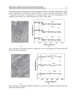
Fig. 3. Mold caused by moisture in the wall cavity.
6
For example, The Rocky Mountain Masonry Institute, Denver, CO; The Brick Industry Association,
Reston VA; The Portland Cement Association, Skokie, IL.
7
For example details and specifications regarding the detailing of masonry can be found at The Brick
Institute of America’s website: www.gobrick.com/TechinicalNotes/tabid/7658/Default.aspx (last
visited on February 13, 2011)
8
The most notable being the Marin County Courthouse, CA.
9
(last visited on February 13, 2011)
Correlation of Professional Performance to Acceptable IAQ in Critical Care Medical Facilities
85
Fig. 4. Water entering the building because of inadequate flashing.
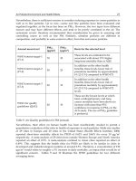
Negative building pressure and improper pressure relationships were the major contributor
to the poor physical environment. Pressure relationships between critical care areas inside
the building with respect to other spaces were not in accordance with [Title 25, Texas
Administrative Code, Chapter 135, Ambulatory Surgical Centers Licensing Rules, (ASCLR),
2009]. Both design and installation defects contributed to these conditions. The design of the
HVAC system was inadequate for humidity control. A test, adjust, balance, and
commissioning process was obviously never completely performed for the performance
aspects of the project other than the air volume measurements. The HVAC control system
was deficient in that it was never commissioned to control to the various pieces of
equipment as an integrated system.
In a response to uncontrolled high indoor humidity, areas were over-cooled including
operating rooms (OR), which resulted in frequent condensation on the interior surfaces,
medical equipment, and supplies to the extent surgeries had to be rescheduled or cancelled.
Water stained building materials, indoor mold growth, temperature fluctuations, high
humidity, and condensation all contributed to an unsatisfactory environment for patients
and staff and violated state licensing rules. Roof top air handling unit panels for access to the
internal equipment and penetrations for conduit, refrigerant lines, etc. leaked water, air, and
dust into the interior of the units. Water intrusion stains, mold growth, and debris were
found in the air handling units and on ceilings below the air handling units. This project
was a classic example of poor coordination. As examples: 1) it is common knowledge that
vinyl wall coverings in a hot and humid climate are doomed to failure, yet vinyl wall
coverings were specified and installed; 2) engineers know that buildings located in hot and
Indoor and Outdoor Air Pollution
86
humid climates need HVAC systems designed to work in that climate, yet only the dry-
bulb/coincident wet-bulb design condition was used for coil selections resulting in high
humidity indoors; and 3) the contractor and subcontractors not only performed substandard
and incorrect work, they ignored the consultants’ notice of such. Both the architect and
contractor failed to provide the quality control and oversight required to deliver an
acceptable project. The architect 1) failed to confirm that the site design conformed to code
and common sense; 2) failed to detail the flashings to prevent water intrusion, and 3) failed
to observe that the weather barrier behind the EFIS was missing. The contractor failed to
notify the architect of this omission. The information regarding all of these discovered
defects was readily available. The defects caused the building materials to be wetted for
prolonged periods of time resulting in mold growth in walls, behind millwork and on
ceilings. In short, this project failed “Design and Construction 101” and corrections that
should have been made in the field are now to be made in the courtroom.
Fig. 5. Typical detail.
Rule # Subject Violation (rule language)
§135.52.(h)(5) HVAC
All rooms and areas in the ASC shall have provision for
positive ventilation. Fans servin
g
exhaust s
y
stems shall be
located at the dischar
g
e end and shall be convenientl
y
accessible for service. Exhaust s
y
stems ma
y
be combined,
unless otherwise noted, for efficient use of recover
y
devices
required for ener
gy
conservation. The ventilation rates
shown in Table 1 of §135.56(a) of this title shall be used onl
y
as minimum requirements, since the
y
do not preclude the
use of hi
g
her rates that ma
y
be a
pp
ro
p
riate.
Correlation of Professional Performance to Acceptable IAQ in Critical Care Medical Facilities
87
Rule # Subject Violation (rule language)
(C)
General
ventilation
requirements
All rooms and areas in the ASC shall have provision for
positive ventilation. The ventilation rates shown in Table 1
of §135.56(a) of this title shall be used onl
y
as minimum
requirements, since the
y
do not preclude the use of hi
g
her
rates that ma
y
be a
pp
ro
p
riate.
(C)(iv)
Temperatures
and
humidities
The desi
g
ned capacit
y
of the s
y
stems shall be capable of
providin
g
the ran
g
es of temperatures and humidities as
shown in Table 1 of §135.56
(
a
)
of this title.
(C)(viii)
Directional air
flow
Ventilation s
y
stems shall be desi
g
ned and balanced to
provide pressure relationships contained in Table 1 of
§135.56
(
a
)
of this title.
(C)(x)
Ventilation
start-up
requirements
Air handlin
g
s
y
stems shall not be started or operated without
the filters installed in place. This includes the 90% and 99.97%
efficienc
y
filters where required. This includes durin
g
construction operations. Ducts shall be cleaned thorou
g
hl
y
and throu
g
hout b
y
a National Air Duct Cleaners Association
(NADCA) certified air duct cleanin
g
contractor when the air
handlin
g
s
y
stems have been operatin
g
without the required
filters in place. When ducts are determined to be dirt
y
or
dust
y
, the department shall require a written report assurin
g
cleanliness of duct and clean air
q
ualit
y
.
(C)(xi)
Humidifier
location
When duct humidifiers are located upstream of the final
filters, they shall be located at least 15 feet from the filters.
Duct work with duct-mounted humidifiers shall be
provided with a means of removin
g
water accumulation.
An adjustable high-limit humidistat shall be located
downstream of the humidifier to reduce the potential of
condensation inside the duct.
(C)(xii)(V)
Pressure
monitoring
devices
A manometer or draft
g
au
g
e shall be installed across each
filter bed havin
g
a required efficienc
y
of 75% or more,
includin
g
laborator
y
hoods requirin
g
hi
g
h efficienc
y
particulate air (HEPA) filters. The pressure monitorin
g
device shall be mounted below the ceilin
g
line within the
ASC such that it can be observed b
y
staff.
(H)
Fire damper
requirements
Fire dampers shall be located and installed in all ducts at
the point of penetration of a required two-hour or hi
g
her
fire-rated wall or floor in accordance with the requirements
of NFPA 101, §18.5.2.
(I)
Smoke
damper
requirements
Smoke dampers shall be located and installed in accordance
with the requirements of NFPA 101, §20 .3.7.3, and NFPA
90A, Chapter 5.
(M) Make-up air
If air suppl
y
requirements in Table 2 of §135.56(b) of this
title do not provide sufficient air for use b
y
exhaust hoods
and safety cabinets, filtered make-up air shall be ducted to
maintain the required air flow direction in that room.
Table 1. Nine of twenty-four rules in ASCLR for HVAC systems were noncompliant.
Indoor and Outdoor Air Pollution
88
3.2 Case study 2 (“CS 2”)
This single story hospital was constructed in 2006. It was 33,000 square feet and constructed
under a design/build delivery system. Its exterior was composed of brick veneer with a
modified bitumen roof over a steel roof structure. The hospital staff noticed mold growth,
wild swings in temperature, and wet indoor environment almost from the day they
occupied the building. An investigation ensued and determined that defects discovered
associated with the shell of the building, or envelope, was a major contributor, along with
the HVAC to the difficulties they were encountering.
Fig. 6. Site drainage violated code and held water against the building.
As in CS 1, common sense and conformance to building codes were not observed at this
project. For example, fig. 7 showed water standing at a door that subsequently entered the
building.
Fig. 7. A flawed detail at the base of the building compounded the threat to the building
posed by standing water.
Correlation of Professional Performance to Acceptable IAQ in Critical Care Medical Facilities
89
A standard detail that would allow a veneer to terminate below grade calls for a flashing to
be installed at a brick or masonry course above grade. The void below the flashing is then
filled with grout that, essentially, makes the veneer below grade a part of the foundation.
Fig. 8. The architect’s detail correctly shows the acceptable method of installing base
flashing when the masonry terminates into grade.
However, he failed to follow manufacturer’s recommendations and buried the exterior
sheathing into the grout fill. Inattention to detail by both architect, who failed to refer to the
manufacturer’s guidelines, and contractor, who failed to notice the defect, led to the
unacceptable condition. As a result of these errors water stands within the wall cavity
posing a continuing threat to building materials.
Fig. 9. Water standing inside the wall cavity.
Indoor and Outdoor Air Pollution
90
Roof coverings have evolved over time allowing several systems from which to choose. All
of these systems have advantages and disadvantages. Depending on the selection,
warranties are available for up to twenty-five years.
10
Manufacturer’s standard details are
typically incorporated into the construction set of drawings. Additionally, there is typically
a requirement within the construction documents (drawings and specifications) for the roof
manufacturer to be present during certain phases of the work, including a pre-construction
meeting. Even so, roofs fail as do roofing contractors. So it becomes essential that the details
are followed by the roofer and the installation is closely scrutinized by third-parties.
Perhaps the biggest challenge in accomplishing a sound roof rests in the details that deal
with roof penetrations by pipes, vents and ducts. In this hospital, the architect and
mechanical engineer provided details to ensure the roof would be sound. Roof details were
included in the construction documents by the architect and the mechanical engineer to
accommodate thermal movement that can result in tearing of the roof membrane, and to
prevent water from entering the building. These details were ignored, resulting in water
damage to materials and, of critical importance, added moisture into the building that
exacerbated the already poor environmental condition within the hospital.
The CS 2 facility is under assault from above and below. Water entered the building from
the site that was poorly graded and was retained in the wall system by a detail that was
poorly executed. As in CS 1, adherence to common sense should have dictated a positive
flow of water away from the structure. The architect was not retained to perform
Construction Administration Services (“CA”), thus severing a key element of quality control
during the construction process. “Full service” would have called for checks and balances as
dictated by the American Institute of Architects Contract Documents A201, General
Conditions and supported by AIA Documents G711 (AIA, 1972), 712 (AIA, 1972), 714 (AIA,
2007) and 716 (AIA, 2004) for use by both the contractor and architect. By not having CA in
place, the contractor implies that all elements of the project conform to the Contract
Documents (plans and specifications), as well as building codes, which is not the case here.
Fig. 10. Water running out of insulation.
10
(last visited on
February 13, 2011)