báo cáo hóa học: " Design considerations for a wearable monitor to measure finger posture" potx
Bạn đang xem bản rút gọn của tài liệu. Xem và tải ngay bản đầy đủ của tài liệu tại đây (704.49 KB, 10 trang )
BioMed Central
Page 1 of 10
(page number not for citation purposes)
Journal of NeuroEngineering and
Rehabilitation
Open Access
Research
Design considerations for a wearable monitor to measure finger
posture
Lisa K Simone*
1
and Derek G Kamper
2
Address:
1
Kessler Medical Rehabilitation Research and Education Corporation, West Orange, NJ, USA and
2
Sensory Motor Performance Program,
Rehabilitation Institute of Chicago, Chicago, IL, USA
Email: Lisa K Simone* - ; Derek G Kamper -
* Corresponding author
Finger flexionRange of Motionsensorshome monitoring
Abstract
Background: Objective measures of hand function as individuals participate in home and
community activities are needed in order to better plan and evaluate rehabilitation treatments.
Traditional measures collected in the clinical setting are often not reflective of actual functional
performance. Recent advances in technology, however, enable the development of a lightweight,
comfortable data collection monitor to measure hand kinematics.
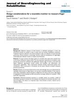
Methods: This paper presents the design analysis of a wearable sensor glove with a specific focus
on the sensors selected to measure bend. The most important requirement for the glove is easy
donning and removal for individuals with significantly reduced range of motion in the hands and
fingers. Additional requirements include comfort and durability, cost effectiveness, and
measurement repeatability. These requirements eliminate existing measurement gloves from
consideration. Glove construction is introduced, and the sensor selection and glove evaluation
process are presented.
Results: Evaluation of commercial bend sensors shows that although most are not appropriate for
repeatable measurements of finger flexion, one has been successfully identified. A case study for
sensor glove repeatability using the final glove configuration and sensors does show a high degree
of repeatability in both the gripped and flat hand positions (average coefficient of variability = 2.96%
and 0.10%, respectively).
Conclusion: Measuring functional outcomes in a portable manner can provide a wealth of
information important to clinicians for the evaluation and treatment of movement disorders in the
hand and fingers. This device is an important step in that direction as both a research and an
evaluation method.
Background
Rehabilitation research has recently begun to emphasize
the use of objective outcome measures to assess the effi-
cacy of rehabilitation treatment or intervention [1]. These
goals could be greatly furthered through the development
of wearable measurement systems that provide an
Published: 01 March 2005
Journal of NeuroEngineering and Rehabilitation 2005, 2:5 doi:10.1186/1743-0003-2-5
Received: 31 January 2005
Accepted: 01 March 2005
This article is available from: />© 2005 Simone and Kamper; licensee BioMed Central Ltd.
This is an Open Access article distributed under the terms of the Creative Commons Attribution License ( />),
which permits unrestricted use, distribution, and reproduction in any medium, provided the original work is properly cited.
Journal of NeuroEngineering and Rehabilitation 2005, 2:5 />Page 2 of 10
(page number not for citation purposes)
opportunity to evaluate how the individual participates in
home and community activities. Information collected in
this manner can provide a more realistic snapshot of activ-
ity and function than traditional methods which restrict
measurements to the clinical or research site. Data
describing actual usage in the home is especially impor-
tant for the hand as hand movement is so closely tied to
performance of functional tasks. In order to understand
how individuals truly interact with their environments,
we wish to obtain quantitative measures of finger flexion
and extension over longer periods of time than tradition-
ally investigated (such as monitoring over a full circadian
cycle).
Unfortunately, rehabilitation researchers have very few
methods available to objectively evaluate hand use and
function outside the clinic, especially for individuals with
moderate to severe reduction in range of motion in the
hand and fingers. Joint range of motion (ROM) is a pri-
mary measure in hand rehabilitation, and is traditionally
assessed using manual goniometry. Manual methods,
however, are limited to static measurements. In addition,
they can be adversely affected by common issues such as
inter- and intra-operator error and operator experience
level [2].
In order to objectively measure hand use outside the
clinic, the selected method must be both portable and
capable of recording continuous streams of data over
time. Automated measurement methods can meet these
requirements as well as eliminate most operator-related
issues. For example, 24-hour monitoring has proven use-
ful for tracking parameters such as heart rate and blood
pressure, and the same concept can be extended to other
useful parameters, although currently no wearable devices
are available to measure finger posture in a similar man-
ner. Practical medical applications can include providing
input for virtual reality therapy, measuring hand function
in the planning of rehabilitation therapies, or evaluating
the outcome of interventions under more realistic
conditions.
Sensor gloves have been proposed to provide automatic
measurements of finger and joint position during differ-
ent activities, with the virtual reality industry continuing
to drive the market for sensor gloves [3]. For example,
Fifth Dimension Technologies (5DT, Irvine, CA) produces
a 5-sensor and a 16-sensor version wireless sensor glove
which transmits data to a nearby computer. Two joints per
finger are captured with these expensive devices (proximal
interphalangeal joint (PIP) and metacarpophalangeal
joint (MCP)) using fiber optic sensors. The White Hand
Group (Mississippi State University) is developing a
lower-cost (<$500) flexion data glove using fiber optics
that has two sensors per finger. The glove is tethered to a
computer and is aimed at VR and gaming applications
rather than accurate measurement applications.
CyberGlove (Immersion Corporation, San Jose, CA) con-
tains 5 to 22 "patented bend-sensing technology" strain
gauges to measure individual joint movements. This
glove, however, is very expensive and difficult for stroke
survivors to don. The Essential Reality (Mineola, NY) P5
glove also uses bend sensors, Abrams/Gentile flex sensors
(wired flexion measurements), and infrared (IR) emitters
(line-of-site wireless position and rotation measure-
ments). The flex sensors are attached to each finger by
rings between the proximal and distal interphalangeal
joints (DIP). While price of this glove is appealing
(<$200), the glove is not portable and requires the wearer
to keep the top of the glove always facing a fixed antenna
IR receiver.
The Humanglove™ (Humanware S.R.L., Pisa, Italy) is a
flexible glove with 20 Hall effect sensors to measure bend.
The Humanglove was evaluated for feasibility and repeat-
ability in finger range of motion in all joints; work contin-
ues to establish the measurement accuracy [2].
Several research gloves have been reported with no clini-
cal results. Karlsson et al. [4] determined finger flexion by
measuring the pressure changes in airtight polyvinyl tubes
on three fingers. Zurbrügg [5] measured flexion using
potentiometers mounted on the back of the hand,
although the construction is not durable for long term
measurements. Hofmann and Henz [6] used inductive
length encoders attached to a cotton glove to measure
flexion and gestures in real time. The glove is not easy to
put on, and the sensors can move around relative to the
joint position. Jurgens et al. [7] proposed an innovative
method using electrically conducting ink printed on a
flexible polyester plastic for a low cost solution, although
disadvantages include extreme sensitivity to small
changes in temperature, and a moderately slow response
time.
The existing glove systems do not meet the needs set forth
in our device requirements. Although some gloves are
lightweight, others such as force feedback and exoskeleton
based gloves are too heavy and bulky for home use by
individuals with hand impairments. Most are too expen-
sive or require custom sizing to reduce errors; measure-
ment errors are decreased when gloves fit more snugly [2].
However, donning a tight glove can be difficult to impos-
sible for some individuals with movement disorders in
the hand. Full gloves have other limitations as well.
Actions such as wrist flexion and rotation in full fabric
gloves can cause the glove material to move over the skin.
In this case, friction can prevent the material from return-
ing completely to the original position, leaving the
Journal of NeuroEngineering and Rehabilitation 2005, 2:5 />Page 3 of 10
(page number not for citation purposes)
sensors located in different positions over the joints [2].
This source of error is manifested as a drift in measured
bend that is difficult to detect, characterize, and eliminate
from recorded data streams.
The environment proposed for the glove use is also very
challenging. A majority of the existing methods are not
appropriate for wearable measurements in the home and
community, and none are designed for use with clinical
and rehabilitation populations who may exhibit signifi-
cant range of motion restriction in the fingers.
The long term goal of this project, therefore, is to design,
build, and clinically evaluate a novel low-cost wireless
device to measure hand and finger activity while individ-
uals participate in normal home and community activi-
ties. It will be used to study the loss of hand function that
can occur following neurological disorders such as stroke
and traumatic brain injury, and to evaluate how treat-
ments can improve an individual's ability to function in
the home and community environments.
This article describes the design process for the develop-
ment of the glove, discussing wearability issues such as
comfort, durability and weight and focusing on sensor
characterization and selection. The results of an initial
evaluation of measurement repeatability while wearing
the glove are presented. Appropriate characterization of
the glove must occur in two phases: evaluation of the sen-
sors separately, and then evaluation of the entire glove
after appropriate sensors have been identified and charac-
terized. Full repeatability results and measurement accu-
racy will be reported in the future.
Methods
The creation of effective custom measurement systems
requires detailed attention to the requirements and design
analysis phases of the development process. While it may
be tempting to solve multiple problems with one system,
this often leads to overly complicated devices that take too
long to complete, and may not actually meet the core
requirements. To avoid this scenario, the sensor glove
project focused specifically on a set of core requirements
presented below, and pursued a multi-step analysis of the
design to ensure the requirements were being appropri-
ately addressed. The steps include an analysis of glove
construction methods, characterisation of sensors, and
exploration of sensor repeatability and accuracy on the
bench and during subject trials.
The primary requirements fall into four categories.
1) Donning and Removing: The glove must be easy to don
and remove for individuals having reduced range of
motion in the hand and fingers.
2) Comfort and Durability: The glove must be lightweight
and unobtrusive, and permit comfortable wearing for at
least 24 hours. It must not restrict range of motion or rep-
resent a snag hazard during use.
3) Function: The glove must detect a wide range of activi-
ties, including fine motor activities such as writing. Meas-
urements must be accurate and repeatable. The sensors
must not move around, but remain in the same position
with respect to the joints and phalanges over time. The
system must allow the performance of normal daily activ-
ities, although use in water is not required. Measurements
must be repeatable with an error no more than 5% of full
scale.
4) Cost: Manufacturing cost is an important consideration
for several reasons. An inexpensive device allows several
to be deployed simultaneously to perform research stud-
ies more quickly. A low-cost glove can be considered dis-
posable for sanitary reasons. Finally, wearers may
unknowingly limit or modify their hand motions and
activities in an attempt to protect an expensive device. A
low-cost alternative ensures that more realistic and repre-
sentative data are captured and recorded.
As noted, a variety of sensors have been employed to
measure joint angle, including strain gauges or bend sen-
sors, fiber optics, pneumatics, or Hall effect sensors. While
each has advantages and disadvantages, the requirements
for our glove preclude the use of all but the bend sensors.
Using fiber optics to measure bend requires a light source
such as a light emitting diode and a photo detector. The
amount of bend is proportional to the attenuation of
detected light in specially treated sections of fiber that pass
over the tops of the finger joints. Disadvantages of this
method include the complexity of glove construction and
price. Hall effect sensors, which detect magnetic fields,
and can be configured as proximity sensors to provide a
linear output proportional to distance from a magnetic
source. By placing a series of sensors on the back of a glove
in a predefined pattern, the joint angle can be computed
from the changing field strengths measured by the sensors
when the fingers bend. While these devices are small, the
resulting glove can be somewhat bulky and will require a
magnetic source, adding to overall weight. Interference
from other electromagnetic sources is also a concern.
Strain gauges detect stretch produced by joint rotation.
They may have very high accuracy, but are expensive and
often delicate.
Bend sensors offer a lightweight and inexpensive alterna-
tive. These sensors are thin flexible membranes that
change resistance when bent; increasing bend angle is
generally associated with increased measured resistance.
One or more layers of carbon and a conductive material
Journal of NeuroEngineering and Rehabilitation 2005, 2:5 />Page 4 of 10
(page number not for citation purposes)
are applied over a thin substrate. Depending on the sensor
type, bending motion forces conductive particles further
apart, increasing the resistance to current flow. These sen-
sors are popular for detecting obstacles and measuring
large changes in bend angle, and are proposed for accurate
measurement of finger posture. However, most exhibit a
time-varying creep behavior when held in a fixed bent
position that reduces the accuracy of measurement. We
sought to find bend sensors that would be feasible.
Glove Construction Methods
In order to explore the first two requirements, ease of don-
ning and comfort/durability, several prototype glove sys-
tems were created in order to identify the best materials
and construction methods to satisfy these requirements.
Several materials were evaluated, including blends of
Lycra
®
, Nylon and cotton. The material must exhibit
stretch so that finger motion and bending are not
restricted. While some blends resisted finger motions,
most were flexible enough that the wearer could forget the
glove was on. A discussion of the process and final selec-
tion of glove materials and application method can be
found elsewhere [8].
The final glove material is a 93% Lycra
®
/ 7% Nylon blend;
it is used to create thin sleeves into which the sensors are
inserted. One sleeve is attached to the back of each finger
in order to locate the sensor directly over each joint; the
optimal adhesive is very thin, double-sided toupee tape.
Applying the sensors to the back of the fingers, rather than
using a traditional glove that must be donned, allows easy
application and removal for individuals who cannot fully
open all fingers to put on a traditional glove. Total glove
cost without sensors is less than $2.50.
Comfort and durability were evaluated over a 24 hour
period. The glove survived intact and did not impede any
activities other than showering and tucking in a shirt.
Because the sensors are attached to the back of the hand,
the palmar surface of the hand is uncovered and free of
obstruction, leaving the sense of touch intact. While only
one individual was used to narrow down the different
prototype ideas, 24 individuals (12 with brain injury and
12 healthy controls) are currently participating in a study
to more fully evaluate the glove configuration and
performance.
Sensor Repeatability
An early decision was made to use an inexpensive bend
sensor as the sensing element for its low profile, light
weight, and low cost. While the first prototype glove has
only 5 sensors, the design provides the flexibility to add
additional sensors for all joints and for finger adduction/
abduction. Sensors from several manufacturers were char-
acterized in order to determine if measurements were
repeatable and if large changes in finger posture and fine
motor control could be captured. In addition, the calibra-
tion relationship between bend angle and measured
resistance was evaluated.
The importance of repeatability testing cannot be overem-
phasized. The sensors were evaluated separately before
being incorporated into the sensor glove. Two types of
tests were performed using a set of tubes of known diam-
eter: 1) determination of full scale and the resistance-bend
relationship (using tube diameters: 4", 3", 2", and 1.5", 1"
and 0.75"), and 2) evaluation of measurement repeatabil-
ity (using the 3" diameter tube). A physical guide was
placed on each tube to ensure that the sensor was placed
in the same location on the tube each time it was applied.
From four to ten sensors from each manufacturer were
evaluated. To test the sensors, each was initially placed flat
on the table for several seconds, then bent over a single
calibration tube for 30 to 60 seconds, and then placed flat
again. Resistance readings were taken during each phase.
The expected profile for this activity should look like a rec-
tangular wave between two resistance values: a lower
resistance value in the flat position, then the higher value
when bent on the tube, and ending with the original
lower flat value. Multiple measurements were taken to
evaluate the variation in sensor outputs, and to construct
a bend resistance versus tube diameter relationship that
could be used for calibration purposes.
Full scale is determined from the endpoints of the calibra-
tion relationship. The minimum measured resistance
value corresponds to the flat position, and the maximum
resistance value is represented by the resistance measured
on the 0.75" calibration tube. The maximum value is an
estimate of what would be observed in human subjects
because the bending radius over a finger joint is not
exactly replicated by bending over different diameter
tubes; however, making this assumption allows the differ-
ent sensors to be compared to one another for selection
purposes. Full scale error is computed as the percent
change in resistance measured while a sensor is fixed
unmoving on a calibration tube with respect to the full
scale range.
A second error is also reported, and is calculated as the
percent change in the peak sensor resistance with respect
to the magnitude of the step function rise in resistance
when the sensor is positioned on a calibration tube. This
error calculation was also selected for comparison because
a number of everyday activities such as grasping and mov-
ing objects find the hand in roughly this position.
As discussed in the results section, additional analysis was
performed to explore an unexpected time-varying behav-
ior of the sensors. Collection of these data and of the data
Journal of NeuroEngineering and Rehabilitation 2005, 2:5 />Page 5 of 10
(page number not for citation purposes)
described in the next section was performed using a host
computer with an 8 channel 16-bit A/D card. The sensors
were connected to an interface box and data on all sensors
was collected at 100 Hz using LabView (National Instru-
ments, Austin, TX). Analysis was performed using Micro-
soft Excel.
Sensor Glove Repeatability
A major concern in developing a measurement method is
that measurements are repeatable. If the bend sensors and
the configuration of these sensors on the fingers will be
used for several measurements during the same session, or
for measurements over several sessions, then repeatability
must be established before the data can be given credence.
Rigorous validation of repeatability, however, is often
lacking from descriptions of various "data gloves."
One method to evaluate repeatability of sensor glove-type
devices has been proposed by Wise [9] and expanded by
Dipietro [2]. The method was specifically developed for
devices that perform semi- or fully-automated goniomet-
ric measurements. Repeatability was established using a
custom mold created by each subject. The mold was made
while the subject simulated a grip position around a wet
mixture of Plaster of Paris. After the mold dried, it was
used to ensure that the subject's finger positions were
identical for several consecutive gripping actions on the
mold. Testing with 5 healthy control subjects revealed
errors that led to recommendations for improvements in
measurement methodology. Dipietro [2] repeated these
procedures with some clarifications in hand position in
the evaluation of the Humanglove, and echoed the need
for standardized testing protocols for sensor glove devices.
This standardized repeatability testing protocol procedure
includes four tests. We will use two, Tests A and C, which
focus on repeatability of multiple measurements over a
single data collection session. Tests A and C are performed
here because the first focus of the glove is for single data
collection sessions (which can last up to 24 hours). The
protocol used here follows the modifications proposed in
[2]; an overview of the tests appears below.
Test A: A roughly cylindrical plaster mold is custom cre-
ated for each subject to ensure that the fingers are flexed
to the same position for each test. The participant clenches
the mold for 6 seconds and then releases the mold for 6
seconds. This clench/release cycle is repeated 10 times.
Repeatability measurements are taken from each sensor
during the clench phases.
Test C: The participant places the hand on a table top and
alternately raises the hand and lightly flexes the fingers,
and returns the hand to the table top for 6 second each.
Repeatability of the flat hand position is explored in this
test. In order to achieve repeatability in hand and finger
position, and outline of the hand profile is drawn on
paper and placed on the table. This cycle is also repeated
10 times.
For each test above, the participant rested for at least 1
minute, and then repeated the entire test. This was done
10 times for both Test A and Test C, for a total of 100 grip/
release cycles for each test. Descriptive statistics are com-
puted (mean, standard deviation, and coefficient of varia-
tion). The percent coefficient of variation (standard
deviation divided by the mean*100%) is used to compare
the measurement variability among the five digits and
between the two repeatability tests.
Results and Discussion
Glove Construction
Figure 1 shows a prototype of the sensor glove monitor.
For the test shown here, one sensor was used to measure
flexion of each metacarpophalangeal (MCP) joint. The
sensors are located inside the beige sensors sleeves, which
are attached to the back of the metacarpals and proximal
phalanges. The sensors do not move relative to the joint
under measurement. The forearm-mounted box contains
signal conditioning. In the next prototype, the box will
also contain a wireless transmitter and the cable from the
left of the box will be removed, allowing the participant to
move around freely. Instead of Velcro bands, a comforta-
ble band of flexible material will hold the box to the fore-
arm. Data will initially be transmitted wirelessly to a
nearby laptop computer, and eventually transmitted wire-
lessly to a waist mounted data recorder. The sensors and
glove sleeves weigh less than 7.1 grams; adding the signal
conditioning box increases the weight to 85 grams. The
final device will have the added weight of a battery and
small wireless transmitter.
Sensor Repeatability
Performing sensor evaluation and characterization early
in the design process allowed us to identify several short-
comings of commercial bend sensors and eventually
select an appropriate sensor.
The first sensor evaluated was the Abrams-Gentile Enter-
tainment, Inc. (New York, NY) sensor patent #5,086,785.
Attempts to measure repeatable bend resistance versus cal-
ibration tube diameter failed because the measured resist-
ance decayed over time. The Abrams-Gentile sensor
exhibits the most common behavior that we will refer to
as Type A behavior, and it appears in Figure 2 as line "AG".
The sensor reached a peak resistance value just as it was
wrapped around the calibration tube, with an immediate
decay in resistance over time. We expected that the sensor
values would be constant; however, the drift in measured
resistance prevented an accurate and repeatable
Journal of NeuroEngineering and Rehabilitation 2005, 2:5 />Page 6 of 10
(page number not for citation purposes)
measurement of bend. To eliminate other potential
sources of error, the analysis was repeated on ten other
sensors, and the problem finally isolated to the sensors by
testing each directly using an ohmmeter.
The average decay in resistance while on the tube was
computed. After 30 seconds, the average error for the
Abrams-Gentile sensors was 9.5% of full scale, and 24.4%
of step function rise resistance (Table 1). The Abrams-
Gentile sensor never settled on a final resistance value, but
over an extended two-day data collection session contin-
ued to slowly decay. While these sensors are appropriate
for many applications such as position detectors and indi-
cators of gross movement, we determined that they are
not appropriate for accurate and repeatable measure-
ments of finger flexion.
The same testing was repeated using sensors from Spectra
Symbol (Salt Lake City, UT). Similarly, the step function
rise in resistance measured on application to the 3" cali-
bration ring dropped 31.8 % in the first 30 seconds (Fig-
ure 2, Type A: SS). Again, the sensor is better suited to
sensing a change in angle, rather than the magnitude of
the change. A calibration relationship was not explored
because the magnitude of the error was so large.
Six different sensor configurations were evaluated from
Flexpoint (South Draper, UT). These included flex sensors
with an overlaminate adhered by a pressure sensitive
adhesive (sensor #1), with a robust polyimide overlami-
nate (sensor #2), with no overlamination but with a stiff
backer (sensor #3), and an overmolded sensor (sensor #4)
for harsh environmental conditions. Representative con-
tours for the 3" calibration test are shown in Figure 2,
labelled "FP: #1, 2, 4, and 5" Sensor 3 exhibited the same
large decays observed with the Type A Abrams-Gentile
and SpectraSymbol sensors shown in the figure. In con-
trast, sensors 1 and 2 (Type B) responded to the initial fast
bend over the tube with a slow rise in resistance that never
reached a peak. When the sensors were removed from the
tube and placed flat again, the resistance decayed but did
not reach baseline values for many minutes. Sensor 4
(Type C) exhibited a fast response to a peak value,
dropped 15% of the rise amount and then slowly recov-
ered the 15% over several minutes, but never returned to
the baseline value when placed flat at the end of the test.
None of these sensors (1–4) is appropriate for the sensor
glove. However, in consultation with the company
describing our exact needs, a solution was identified. The
bend sensors are generally not supplied without some
type of protection layer. However, these layers tended to
Prototype of the sensor glove monitorFigure 1
Prototype of the sensor glove monitor. The monitor is shown with five sensors placed on the MCP joints. Signal condi-
tioning is contained in the box. The next prototype will include a wireless link for data download to an external computer, ena-
bling the removal of the cable extending out of the back of the box.
Journal of NeuroEngineering and Rehabilitation 2005, 2:5 />Page 7 of 10
(page number not for citation purposes)
Sensor time-varying propertiesFigure 2
Sensor time-varying properties. Each of several sensors is placed on a calibration tube for at least 30 seconds, and then
stretched flat on a table in order to verify that a constant relationship exists between bend angle and measured resistance. Ide-
ally, these curves should be flat but a significant time-varying decay renders most unusable for this application. This figure
shows several representative curves for the three manufacturers evaluated. AG: Abrams-Gentile sensors, SS: SpectraSymbol
sensors, FP: Flexpoint sensors (several types).
Table 1: Sensor decay over time for three sensor types fixed over a 3-inch tube
% Full Scale % Step Function Rise
Time (sec) Abrams-Gentile Flexpoint Time (sec) Abrams-Gentile Spectra Symbol Flexpoint
0 0.0% 0.0% 0 0.0% 0.0% 0.0%
2 3.9% 0.3% 2 9.9% 15.2% 2.6%
4 5.2% 0.3% 4 13.4% 17.8% 3.2%
15 7.9% 0.6% 15 20.4% 25.7% 6.1%
30 9.5% 0.8% 30 24.4% 31.8% 8.9%
Journal of NeuroEngineering and Rehabilitation 2005, 2:5 />Page 8 of 10
(page number not for citation purposes)
cause the observed decay problems, making these sensors
inappropriate for this application. Evaluation of bare sen-
sors (Figure 2, Type D) revealed the initial peak resistance
followed by decay; however, the magnitude of the decay
after 30 seconds was only 0.8% full scale or 8.9% of step
function resistance rise, which is acceptable for this appli-
cation. The bare version of the sensor is approximately
$7.10 in low quantities. The average relationship between
bend angle and resistance for 5 sensor trials is shown in
Figure 3. The error results from all sensors are shown in
Table 1.
Bend sensors are used in a number of university and home
projects, despite our findings that most are not repeatable
for moderate to fine resolution measurements. Instead,
most are appropriate for binary ON/OFF applications, or
applications that do not require high resolution or highly
repeatable results. Examples include using the sensor as a
"whisker" to sense the proximity of an object for collision
detection, for detecting large changes in bend angle, or for
more unique applications such as adding effects to music
[10]. Others report early results for such implementations
as measurement of foot flexion for biofeedback [11]
although follow-up work on calibration and analysis
methods is still pending. We located no references validat-
ing and using these sensors, and only one reference that
indicated that the Abrams-Gentile sensor was "difficult to
work with" [12]. For the measurement device described
here, repeatability of measurement is an important crite-
rion. Only the bare Flexpoint sensor was found to be
appropriate for measuring fine changes in bend angle in a
repeatable manner. If another sensor is used in this appli-
cation, there is no way to determine the actual bend radius
because a wide range of measured resistance values
(caused by the decay) correspond to a single bend radius.
Sensor Glove Repeatability
Repeatability testing began with the evaluation of the sen-
sors and final sensor selection, and continues by consider-
ing the performance of the entire glove. The sensor glove
repeatability testing has been performed with one partici-
pant, who is the first in a study that will include repeata-
bility testing for 6 healthy controls. All participants
complete an Institutional Review Board consent form and
the required HIPAA authorization forms. The plaster
mold was created as shown in Figure 4.
The results of Test A reveal the repeatability of measure-
ment in the grip hand position. Coefficient of variability
for all five digits is less than 6% (thumb: 0.55%, index:
5.37%, middle: 1.91%, ring: 4.61%, pinkie: 2.36%). Fig-
ure 5 shows the mean and standard deviation of measured
Resistance – bend relationship of the Flexpoint sensorFigure 3
Resistance – bend relationship of the Flexpoint sen-
sor. The Flexpoint sensor has a nonlinear relationship
between measured resistance and bend diameter, as found
by measuring resistance for sensors wrapped around calibra-
tion tubes of different diameters. For illustration purposes,
the relationship presented here is an average of several sen-
sors; a separate relationship will be measured for each sen-
sor used in the sensor glove.
Grip moldFigure 4
Grip mold. The grip mold is custom made for each subject.
It provides a repeatable position for the fingers to assume for
multiple grip-release activities in order to evaluate repeata-
bility of measurement.
Journal of NeuroEngineering and Rehabilitation 2005, 2:5 />Page 9 of 10
(page number not for citation purposes)
MCP joint position while gripping the mold 100 times.
The mean values indicate the average resistance of the sen-
sors when the fingers are gripping the mold. In this test,
the actual mean value of bend is not critical, it just repre-
sents the joint position when the mold was made. In addi-
tion, these values are not calibrated. For this individual,
the thumb MCP is the least bent (having the lowest resist-
ance values) while the ring and pinkie fingers are signifi-
cantly bent. The repeatability information is located
within the very low coefficient of variation, or variation of
the measured values about the mean.
The results for Test C show the repeatability in the flat
hand position with the sensors fully extended. Coefficient
of variability for all five digits is less than 1% (thumb:
0.18%, index: 0.08%, middle: 0.05%, ring: 0.07%, pinkie:
0.15%). Figure 6 shows the mean and standard deviation
of measured MCP joint position while placing the hand
flat 100 times. Descriptive statistics and coefficient of var-
iability for Tests A and C are shown in Table 2. The varia-
tion in measurements for the flat hand position is
extremely small over the 100 cycles, which is very encour-
aging considering that the flat hand position is only
guided by an outline of the hand on the tabletop. Five
additional participants will complete this repeatability
testing and results presented in the future.
These results are similar to [2] in that the measurement
repeatability was better in the flat hand (Test C) case than
in the grip mold case (Test A). Dipietro [2] speculated that
the "hand is positioned more accurately by placing it
flat than by clenching the mold." Wise [9] also noted
that "increasing forces produced errors in the glove
measurements, especially in the MCP joints." We
observed through separate experimentation that in the flat
hand position, the musculature in the hand tends to relax.
In the grip position, in contrast, the muscles must main-
tain at least a minimal contraction in order to prevent
dropping the mold. Varying levels of grip force can be
applied, and the finger positions can be shifted slightly
while still holding the mold closely. The measured varia-
tions in resistance easily accounted for the observed vari-
ations in the grip repeatability test results. The solution
was to ask the individual to only grip the mold with
enough strength to hold it, and that instruction will be
given to future participants. While executing these tests
can be challenging, we must concur that standardized test-
ing is vital to ensuring that the collected data are useful
and repeatable.
Conclusion
The glove developed in this research is unconventional,
and its uniqueness owes to the appropriate attention to
the core requirements during the design analysis phase.
The glove provides a novel method to evaluate actual
functional capacity, starting with the dynamic evaluation
of ROM as individuals participate in their normal daily
activities.
The glove is not a generic solution, but a specific device to
measure finger posture in an underserved population.
Repeatability testing of grip positionFigure 5
Repeatability testing of grip position. Repeatability test-
ing of one participant for the grip test (Test A). Means and
standard deviations are shown. Mean values differ because
each finger is in a different position when gripping the mold.
Repeatability information is contained in the variation around
the mean.
Repeatability testing of flat hand positionFigure 6
Repeatability testing of flat hand position. Repeatability
testing of one participant for the flat hand test (Test C).
Means and standard deviations are shown. Mean values are
similar because all fingers are straight when data collection
occurs.
Journal of NeuroEngineering and Rehabilitation 2005, 2:5 />Page 10 of 10
(page number not for citation purposes)
Bend sensors were selected for their lightweight low pro-
file, and for cost effectiveness. Although significant error
can be introduced by using bend sensors, sensors with the
appropriate repeatability characteristics have been
identified. The bare Flexpoint sensors provided repeatable
measurements with a 30 second error of 0.8% full scale, as
compared to 9.5% for the next best solution, the Abrams-
Gentile sensor. The overall glove configuration shows
strong promise for providing repeatable measurements
over long periods of time without undesired movement
over the joints. Coefficient of variability averaged 2.96%
and 0.10% across the five digits for the grip test and flat
hand test, respectively. The glove is low cost; the total cost
for the disposable portion of the device (glove material,
adhesive and sensors) is less than $40, which is signifi-
cantly less than any other reported solution. The glove can
be used not only to measure flexion in individuals with
reduced range of motion who cannot wear traditional
measurement gloves, but also to measure passive ROM
and cleaning activities in individuals who cannot initiate
volitional activity in their affected hand.
Future directions include completion of the current study
to establish repeatability and to identify calibration
methods. The wireless link will be added midway through
the study to provide full wearability and unencumbered
movement, paving the way for extended studies in the
home and community environments.
Competing interests
The author(s) declare that they have no competing
interests.
Authors' contributions
LS made substantial contributions to the conception and
design of the device and drafted the manuscript. DK iden-
tified a need for the device, contributed to the require-
ments and design of the device, and participated in
revisions of the manuscript.
Acknowledgements
This work was supported by a grant from the Foundation of University of
Medicine and Dentistry of New Jersey, and by the Henry H. Kessler
Foundation.
References
1. Finch E, Brooks D, Stratford PW, Mayo NE: Physical Rehabilitation Ouc-
tome Measures: A Guide to Enhanced Clinical Decision Making Second
edition. Hamilton, Ontario: BC Decker; 2002.
2. Dipietro L, Sabatini AM, Dario P: Evaluation of an instrumented
glove for hand-movement acquisition. Journal of Rehabilitation
Research and Development 2003, 40:179-190.
3. Youngblut C, Johnson RE, Nash SH, Wienclaw RA, Will CA: Review
of virtual environment interface technology. (No. IDA Paper P-
3186): Institute for Defense Analyses, 1801 N. Beauregard Street, Alexan-
dria Virginia 1996 [ />tions.html].
4. Karlsson N, Karlsson B, Wide P: A glove equipped with finger
flexion sensors as a command generator used in a fuzzy con-
trol system. In Proceedings of the IEEE Instrumentation & Measurement
Technology Conference 18–21 May 1998 St Paul, Minnesota, USA;
1998:441-445.
5. Zurbrügg T: Dynamic Grasp Assessment for Smart Electrodes
(GRASSY). Semester Thesis. ETH Zurich (Swiss Federal Institute of
Technology), Department of Information Technology and Electrical
Engineering 2003 [ />].
6. Hofmann F, Henz J: The TU-Berlin Sensor Glove. Diploma thesis
1995 [ />].
Technische Universität Berlin
7. Jurgens J, Patterson PE: Development and evaluation of an inex-
pensive sensor system for use in measuring relative finger
positions. Med Eng Phys 1997, 19(1):1-6.
8. Simone LK, Elovic EP, Kalambur U, Kamper DG: A low cost
method to measure finger flexion in individuals with reduced
hand and finger range of motion. In Proceedings of the 26th Annual
International Conference of the IEEE EMBS 1–5 September 2002 San
Francisco; 2004:4791-4794.
9. Wise S, Gardner W, Sabelman E, Valainis E, Wong Y, Glass K, Drace
J, Rosen JM: Evaluation of a fiber optic glove for semi-auto-
mated goniometric measurements. Journal of Rehabilitation
Research & Development 1990, 27:411-424.
10. Moerlein A: Edward sensorhands. [ />grams/mma/emid/projectreportsS04/moerlein.html].
11. Morris SJ, Paradiso JA: Shoe-integrated sensor system for wire-
less gait analysis and real-time feedback. In Proceedings of the
Second Joint EMBS/BMES 23–26 October 2002 Houston Omnipress;
2002:2468-2469.
12. Cham JG, Stafford B, Cutkosky MR: See labs run: A design-ori-
ented laboratory for teaching dynamic systems. Proceedings of
the 2001 ASME International Mechanical Engineering Congress and Expo-
sition: 11–16 November 2001 New York 2001:1-8.
Table 2: Variability in glove measurements for repeatability Tests A and C
Test A: Grip Mold Test C: Flat Hand
Mean (Ohms) SD (Ohms) CoV Mean (Ohms) SD (Ohms) CoV
Thumb 9138 50 0.55% 8257 15 0.18%
Index 14400 773 5.37% 8562 7 0.08%
Middle 27873 533 1.91% 7992 4 0.05%
Ring 51364 2368 4.61% 8231 6 0.07%
Pinkie 50629 1194 2.36% 7586 11 0.15%