báo cáo hóa học: "Wearable kinesthetic system for capturing and classifying upper limb gesture in post-stroke rehabilitation" pot
Bạn đang xem bản rút gọn của tài liệu. Xem và tải ngay bản đầy đủ của tài liệu tại đây (943.68 KB, 16 trang )
BioMed Central
Page 1 of 16
(page number not for citation purposes)
Journal of NeuroEngineering and
Rehabilitation
Open Access
Research
Wearable kinesthetic system for capturing and classifying upper
limb gesture in post-stroke rehabilitation
Alessandro Tognetti*
1
, Federico Lorussi
1,2
, Raphael Bartalesi
1
,
Silvana Quaglini
3
, Mario Tesconi
1
, Giuseppe Zupone
1
and Danilo De Rossi
1,2
Address:
1
Interdepartemental Research Centre "E. Piaggio", University of Pisa, Via Diotisalvi 2, Pisa, Italy,
2
Information Engineering Department,
University of Pisa, Via Caruso 2, Pisa, Italy and
3
Department of Computer Engineering and Systems Science, University of Pavia, Via Ferrata 1,
Pavia, Italy
Email: Alessandro Tognetti* - ; Federico Lorussi - ; Raphael Bartalesi - ;
Silvana Quaglini - ; Mario Tesconi - ; Giuseppe Zupone - ; DaniloDe
Rossi -
* Corresponding author
Abstract
Background: Monitoring body kinematics has fundamental relevance in several biological and
technical disciplines. In particular the possibility to exactly know the posture may furnish a main aid
in rehabilitation topics. In the present work an innovative and unobtrusive garment able to detect
the posture and the movement of the upper limb has been introduced, with particular care to its
application in post stroke rehabilitation field by describing the integration of the prototype in a
healthcare service.
Methods: This paper deals with the design, the development and implementation of a sensing
garment, from the characterization of innovative comfortable and diffuse sensors we used to the
methodologies employed to gather information on the posture and movement which derive from
the entire garments. Several new algorithms devoted to the signal acquisition, the treatment and
posture and gesture reconstruction are introduced and tested.
Results: Data obtained by means of the sensing garment are analyzed and compared with the ones
recorded using a traditional movement tracking system.
Conclusion: The main results treated in this work are summarized and remarked. The system was
compared with a commercial movement tracking system (a set of electrogoniometers) and it
performed the same accuracy in detecting upper limb postures and movements.
Background
This work deals with the development of an innovative
measuring system devoted to the analysis of the human
movement. Our main aim is to provide a valid alternative
comfortable instrumentation useful in several rehabilita-
tion areas. In particular we focused our attention on the
remote treatment of post-stroke patients [1].
The analysis of human movement is generally performed
by measuring kinematic variables of anatomic segments
by employing accelerometers, electrogoniometers,
Published: 02 March 2005
Journal of NeuroEngineering and Rehabilitation 2005, 2:8 doi:10.1186/1743-0003-2-8
Received: 10 January 2005
Accepted: 02 March 2005
This article is available from: />© 2005 Tognetti et al; licensee BioMed Central Ltd.
This is an Open Access article distributed under the terms of the Creative Commons Attribution License ( />),
which permits unrestricted use, distribution, and reproduction in any medium, provided the original work is properly cited.
Journal of NeuroEngineering and Rehabilitation 2005, 2:8 />Page 2 of 16
(page number not for citation purposes)
electromagnetic sensors or cameras integrated in finer
equipment as stereophotogrammetric systems. In remote
rehabilitation tasks, several disadvantages derive from the
use of these technologies, which are mainly applied in the
realization of robotics or mechatronics machines (such as
MIME or MIT-MANUS [2]) which result invasive, complex
and often unable to satisfy safety requirements for the
presence of mechanical parts in movement. In literature,
several studies are devoted to realize electric devices with
properties of hight wearability [3-5]. The main drawbacks
of wearable sensing systems available on the market are
their weight, the rigidity of the fabric which they are made
of, the dimension of the sensors used, and all the other
properties which make them obtrusive. In particular, con-
ventional sensors often require the application of com-
plex and uncomfortable mechanical plug in order to
position the sensors on garments. In the present work, we
focused our efforts in the realization of a new system for
the measurement of the human upper limb kinematic var-
iables based on a sensorized garment, the Upper Limb
Kinesthetic Garment (ULKG). Lightness, adherence and
elasticity have been privileged in the ULKG realization as
fundamental requirements for its unobtrusivity. These
guidelines have led us to choose an elastic fabric (Lycra)
to manufacture it as a sensorized shirt. In order to equip
the lycra shirt with a sensing apparatus, sensors have been
spread on the fabric by employing an electrically conduc-
tive elastomer (CE). CE deposition does not change the
mechanical characteristics of the fabric. It preserves the
wearability of the ULKG and it confers to the fabric pie-
zoresistive properties related to mechanical solicitations.
This property has been exploited to realize many other
sensorized garments as gloves, leotards, seat covers capa-
ble of reconstructing and monitoring body shape, posture
and gesture [6]. Furthermore, by using this technology,
both sensors and interconnection wires can be smeared by
using the same material in a single printing and manufac-
turing process. This is a real improvement in terms of
comfort performed by the device because no metallic
wires are necessary to interconnect sensors or to connect
them to the electronic acquisition unit. In this way no
rigid constraints are present and movements are
unbounded.
Methods
Materials
CE composites show piezoresistive properties when a
deformation is applied and can be integrated into fabric
or other flexible substrate to be employed as strain sen-
sors. Integrated CE sensors obtained in this way may be
used in posture and movement analysis by realizing wear-
able kinesthetic interfaces [7]. The CE we used is a com-
mercial product by WACKER Ltd (Elastosil LR 3162 A/B)
[8] and it consists in a mixture containing graphite and sil-
icon rubber. WACKER Ltd guarantees the non-toxicity of
the product that, after the vulcanization, can be employed
in medical and pharmaceutical applications.
Kinesthetic Wearable Sensors
In the production process of the ULKG, a solution of Elas-
tosil and trichloroethylene is smeared on a lycra substrate
previously covered by an adhesive mask. The mask has
been designed according to the desired topology of the
sensor network and cut by a laser milling machine. After
the CE deposition, the mask is removed and the treated
fabric is placed in an oven at a temperature of 130°C to
speed up the cross-linking process of the mixture. In about
10 minutes the sensing fabric is ready to be employed to
manufacture the ULKG.
Sensor Characterization
The main aim of the CE sensor characterization has been
the determination of the relation between the electrical
resistance R(t) of a treated fabric sample and its actual
length l(t). Moreover, an analysis of the thermal transduc-
tion properties and aging of the fabric has been executed
[5].
In terms of quasi-static characterization, a sample of 5
mm width shows an unstretched electrical resistance of
about 1 kΩ per cm, and its gauge factor (GF) is about 2.8
, where R is the electrical resistance, l is
the actual length, R
0
is the electrical resistance correspond-
ing to l
0
which represents the rest length of the specimen).
The temperature coefficient ratio is 0.08 K
-1
. Capacity
effects showed by the sample are negligible up to 100
MHz.
Dynamic Characterization
Electrical resistance behavior of the examined CE samples
during a deformation has been fundamental to allow us
to employ them as sensors. Two different issues had to be
addressed to use CE as strain sensors. The first one con-
cerns the length of the transient time, which can take up
to several minutes. It is obvious that these physical sys-
tems cannot describe human movement without a signal
processing devoted to compensate the slowness of this
phenomenon. Moreover, electrical trend of the analyzed
specimen shows some non linear phenomena which are
not negligible under certain working conditions, in partic-
ular when fast deformations are applied. In this work the
following results will be introduced. The typical electrical
behavior of this system, when deformations in length are
applied, will be described. The results of our study will
lead to the formulation of a mathematical model which
approximates the sensor electrical behavior. This model
will be used to implement an algorithm devoted to the
system regulation which consents the sensor length
(GF
lR R
Rl l
=
−
()
−
()
0
0
Journal of NeuroEngineering and Rehabilitation 2005, 2:8 />Page 3 of 16
(page number not for citation purposes)
determination in real time. Finally, two simplified and
faster versions of this sensor length determination tech-
nique will be presented and applied in posture
reconstruction.
The analysis of the electrical trend of CE sensors, when
deformations are applied, has been performed by using a
system realized in our laboratories which can provide
controlled deformations and at the same time can acquire
the resistance value performed by the specimen. A wide
description of this instrumentation and its performances
can be found in [5]. By using this device, several deforma-
tions, which differ in their forms versus time, amplitudes
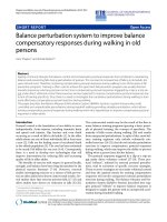
and velocities have been applied to CE specimens. Figure
1, which has been reported as an example of this analysis,
shows the output of a sample stretched with trapezoidal
ramps in deformation having different velocities (t)
(where l(t) is the length of the sample). The main remarks
on sensor electrical behavior are summarized in the
following:
• Both in case of deformations which increase the length
of the specimen and in case of de formations which
reduce it, two local maxima greater than both the starting
value and the regime value are performed.
• If the relationship between R(t) and l(t) were linear, one
of the extrema described in the previous point would be a
minimum.
• The height of the overshoot peaks increases with the
strength velocity ( (t)).
• The relaxing transient time, which lasts up to several
minutes, is too long to suitably code human movement.
Nonlinearity in the functional which relates R(t) and l(t)
suggested us to choose an approximation containing a
quadratic term in the strain velocity ( (t)). Let us
consider:
where a
1
, a
2
and a
3
are three nonzero real numbers. By
using experimental data, we have verified that when the
specimen is motionless, i.e. (t) = 0, the signal deriving
from the sensor is representable by a linear combination
of exponential function:
and the values
ω
i
do not depend on the amplitude and
velocity for a wide range of the solicitation previously
applied (0 – 50 per cent of the rest length and 0 – 0.1 m/
s), but they vary only according to the shape and the
dimensions of the specimen and on the percentages of the
components in the mixture used to realize it [9]. By con-
sidering g(t) as the input function of the differential linear
system
where , we have obtained encourag-
ing results in signal modelling [9]. In particular we have
approximated the sensor behavior as the solution of a sec-
ond order linear system based on equation (3):
with
Response of a CE sensor solicited by trapezoidal ramps in deformationFigure 1
Response of a CE sensor solicited by trapezoidal ramps in
deformation.
l
l
l
gt alt alt alt
()
=
()
+
()
+
() ()
123
2
1
l
Yt c ce ce
t
p
t
p
()
=+ ++
()
−
−
01
1
2
ω
ω
…
xt Ax
()
=
()
+
()
()
t
gt
0
3
x =
RRR
T
…
R
R
e
R
R
e
g
d
tt
t
t
t
=
+
()
(
−
()
−
()
∫
A
A
0
0
0
0
0
4
τ
τ
τ
))
A =
−
−+
()
()
0
1
5
12
12
ωω
ωω
Journal of NeuroEngineering and Rehabilitation 2005, 2:8 />Page 4 of 16
(page number not for citation purposes)
where
ω
1
and
ω
2
are the two poles of the linear system (4).
This relation provides an obvious (almost theoretically)
method to calculate g(t). Since equation (3) contains only
R(t) and its derivatives, it s simple to determine the value
of g(t). So to obtain l(t)in real time it is necessary to inte-
grate the differential equation (1) (in which the three
parameters a
1
, a
2
and a
3
have been identified through the
values of peaks excursions in the responses of the sensor).
Unfortunately, equation (1) is not generally integrable
when g(t) is unknown and its solution l(t) has to be
numerically computed. This is not a simple issue because
the acquired data are affected by noise and sample errors.
Good results have been obtained off-line by using a wide
digital filtering which used the average value of a large
number of sample to reduce the noise, but introduced a
signal delay [9]. Next developments will be aimed at
implementing the length detection in real time during a
motion.
Conversely, the problem has been already addressed
when the system is motionless, i.e. (t) = 0 and g(t) =
a
1
l(t), and will be treated in the next section.
Transient Time Reduction
After a mechanical solicitation, CE sensor resistance
changes according to equation (2). Unfortunately, the
values determined for
ω
i
and the resulting transient time
do not allow to directly employ the acquired signals for
our applications. On the other hand, by using equation
(2) it has been possible to regulate the sensor response by
calculating the coefficients c
i
(and in particular c
0
, which
represents the final value of the signal) early with respect
to the transient time duration. Since the pole values are
invariant with the deformation, in order to apply relation
2, they have to be calculated only once, during the system
parameter identification. If the
ω
i
are known only the c
i
remain undetermined and have to be computed in real
time after each deformation. The parameter identification
is realized by an utility package which performs a minimi-
zation of the quantity
over a lattice L which spans the variables c
0
c
p
,
ω
1
ω
p
and where y is a k-dimensional vector containing the
acquired data during the transient time after a solicitation.
The choice of k is due to the noise which affects the signal.
The precision in the parameters identification increases
with its value. Practically this procedures is repeated sev-
eral times and the values obtained for the
ω
i
are the aver-
age response evaluated on all the trials. When we have
determined the pole values, after each solicitation coeffi-
cients c
0
c
p
have to be re-calculated to return the steady-
state response and the related sensor length. We have
developed two different procedures to calculate them. The
first one consists in considering the iterate p derivatives of
function (2) with respect to t. If k ≥ p, the set of these equa-
tions evaluated on k samples and compared with the
numerical derivatives of the signal stored in vector y con-
stitutes a welldimensioned linear system in the variables
c
i
, which can be calculated with low computational cost.
Although this methodology is clear and elegant, it
presents a serious disadvantage. The computation of the
numerical derivatives of the signal y is corrupted by the
noise which affects the signal. Moreover the sampling
noise due to the analog-digital converter in the electronic
acquisition system is amplified by its derivation. Practi-
cally, this strategy is inapplicable in this form. Results
remarkably improve if analogical derivators are used. This
solution addresses the problems introduced by the noise,
but dramatically increases the dimension of the electronic
acquisition system, because in addition to the derivators,
each signal and its derivatives have to be individually
acquired, and the number of the acquisition channels
increases according to derivative order we use [10].
To address this issue and attenuate noise components due
to the coupling between high impedence front-ends to the
connecting wires embedded in the garment and power-
lines [10], we developed an algorithm based on iterative
integrations of equation (2). Coefficients {c
i
}
i = 0 p
are in
this case the solution of an over-dimensioned linear sys-
tem n × p, obtained by integrating n times equation (2) on
the interval [t
0
, t
k
]. It is trivial to prove that the obtained
system is consistent for n ≥ p and k ≥ p by computing the
jacobian matrix of the system in its parametrical form. The
choice of n >p produces a filtering (based on a least square
evaluation of redundant data) of signals while the coeffi-
cients are calculated. A further stabilization is due to the
integration on all the interval where eq. (2) holds, by col-
lecting all the information previously stored. No particu-
lar disadvantages arise from this methods. All the
calculation is digitally computed with neither increasing
the dimension of the electronic acquisition system nor
introducing or amplifying further noise. The main short-
coming of this approach is that it requires that one detects
each movement because equation (2) holds when the
specimen is motionless, only, and the numerical integra-
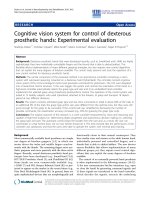
tion has to be reset after each solicitation. Results are
reported in Figure 2
Realization of the Upper Limb Kinesthetic Garment
The sensing fabrics described above can be employed to
realize wearable sensing systems able to record human
posture and gesture, which can be worn for a long time
with no discomfort. In order to realize the ULKG, we have
integrated sensors into a shirt connected to an electronic
unit which operates a pre-filtering process. The very inno-
vative goal we obtained consists in printing the set of
l
J
j
k
=−+ ++
()
=
−−
∑
()yc ce ce
j01
t
p
t
2
jpj
1
1
6
ωω
…
Journal of NeuroEngineering and Rehabilitation 2005, 2:8 />Page 5 of 16
(page number not for citation purposes)
sensors and the connecting wires directly on the fabric by
using CEs (in the earlier prototypes the interconnections
were realized by means of metallic wires [5], which might
bound movements and create artifacts). In order to realize
a sensorized shirt able to monitor the kinematics of the
upper limb, we have to determine position and orienta-
tion of sensors attached to the considered joints. A crucial
point here is based on the observation that a redundant
number of sensors (i.e. a number of sensors bigger than
the number of the degrees of freedom to of the system
under consideration) distributed on a surface can provide
enough information to infer the essential features con-
cerning the posture of a subject, neglecting the precise sen-
sor location. We borrow this approach from biological
paradigms [6,7]. A theoretical approach has been tried, by
searching an optimization criterion to maximize the glo-
bal content of information collected by the sensor system
[11]. Unfortunately, this technique is very onerous in
terms of required computational resources. The optimiza-
tion of this calculation is at the present under study.
Finally, an heuristic approach has been adopted. By real-
izing a sample of sensorized fabric and by placing it
around the considered joints during the execution of nat-
ural movements we have determined the set of position
which produces meaningful outputs in terms of move-
ment reconstruction.
ULKG Electrical Model and Electronic Implementation of
the Acquisition Technique
All the remarks and trials exposed in the previous section
lead us to design the adhesive mask used to smear sensors
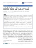
and wires reported in Figure 3. The sensorized prototype
shirt, realized by using this mask, is showed in Figure 4.
The bold black track of Figure 3 represents the set of sen-
sors connected in series (S
i
, and covers the joints of the
upper limb (shoulder, elbow and wrist). The thin tracks
(R
i
, Figure 3) represent the connection between the sen-
sors set and the electronic acquisition system. Since the
thin tracks are made of the same piezorestive CE mixture,
they undergo a not negligible (and unknown) change in
their resistance when the upper limb moves. Therefore the
analog front-end of the electronic unit is designed to com-
pensate the resistance variation of the thin tracks during
the deformations of the fabric. The electric scheme is
shown in figure 3. While a generator supplies the series of
sensors S
i
with a constant current I, the acquisition system
Output of a CE sensor (Voltage vs. Time) for three different deformation steps imposed (above) and treated signal (below)Figure 2
Output of a CE sensor (Voltage vs. Time) for three different deformation steps imposed (above) and treated signal (below).
The transient time has been reduced.
Journal of NeuroEngineering and Rehabilitation 2005, 2:8 />Page 6 of 16
(page number not for citation purposes)
is provided by an high input impedance stage realized by
instrumentation amplifiers and represented in Figure 3 by
the set of voltmeters. Thanks to this configuration, only a
little amount of current flows through the connecting
wires, which have resistance values R
i
, and so the voltages
which fall on R
i
are negligible if the current I, which flows
in the series of sensors, is big enough. In conclusion, the
voltages measured by the instrumentation amplifiers are
equal to the voltages which fall on the S
i
that is related to
the resistances of the sensors. In this way, the thin tracks
perfectly substitute the traditional metallic wires and a
sensor, consisting in a segment of the bold track between
two thin tracks, can be smeared in any position to detect
the movements of a certain joint.
The ULKG Working Modes: Reconstruction of Kinematic
Configurations
In order to clarify how posture detection can be done by
using a kinesthetic garment, some remarks are necessary.
First, in order to formally define a posture, it is necessary
to develop a geometrical model of the kinematic chain
under study. This can be easily done by fixing a certain
number of cartesian frames, one for each degree of free-
dom considered and relating them with the segments
which compound the kinematic chain. A kinematic con-
figuration consists in the set of the mutual positions of the
cartesian frames. Obviously, the entire set of the mutual
positions is not necessary to reconstruct a posture exactly,
The electronic acquisition scheme (on the left) and the mask utilized for the realization of the ULKG (on the right)Figure 3
The electronic acquisition scheme (on the left) and the mask utilized for the realization of the ULKG (on the right).
The UKLG prototypeFigure 4
The UKLG prototype.
Journal of NeuroEngineering and Rehabilitation 2005, 2:8 />Page 7 of 16
(page number not for citation purposes)
and a minimal set can be chosen in many different ways.
The Denavit-Hartemberg formalism [12] is an example of
a method which fixes the exact number of relations
between frames and gives a standard method to write their
positions in terms of rotation and translation affinities,
for rotational and translational joints.
When the ULKG is worn by a user which holds a given
position described by the geometrical model, the set of
sensors assumes a value strictly related to it. If the number
of sensors is large enough and if the sensor locations are
adequate, the values presented by them uniquely charac-
terize the considered position. Let be the sensor
space, i.e. the vectorial space whose elements contain the
values presented by sensors and where k is equal to the
number of sensors in the ULKG and let be the
space containing the kinematic configurations, i.e. the
space of the lagrangian coordinates that define mutual
segment positions in an upper limb kinematic model,
where n is equal to the number of degrees of freedom con-
sidered. To execute a reconstruction of the kinematic con-
figuration, by knowing the sensor status, a function F
which maps S into Θ has to be defined. We have imple-
mented F both by a clusterization of the space S via a clus-
tering norm technique into the space Θ and by the
interpolation of the discrete map produced by the cluster-
ization. In the present application the first solution has
been applied by using the norm
as a clustering function, where ∈ S is a k-dimensional
vector which represents a center of the clusterization lat-
tice and s ∈ S is a k-dimensional vector representing the
real values assumed by the sensors. Each points s* whose
distance from a certain point of the lattice * is less than
a previously fixed threshold
ε
is related to the value that
the map assumes in *. The values which the function
holds in the points of the clusterization lattice is experi-
mentally acquired. The other implementation of F is
described in [7] and will be summarized in section The
ULKG as Posture Detector.
Kinematic Models of Human Joints – The Upper Limb
Model
In many disciplines as biomechanics, robotics and com-
puter graphics, geometric hierarchical structures are used
in articulated body modeling for robots, human or other
creatures representations. An articulated body can be
thought as a series of rigid segments connected by joints.
A biological kinematic chain is exactly an articulated
body. In the present work we implement an upper limb
kinematic model by employing ideal joints in order to
maintain a practical parameterization of movements
without trivializing human motion. From a macroscopic
point of view, a complete upper limb model would have
at least 7 DOFs, corresponding to rotational movements.
These ones, described by kinesiology [13], are reported in
Table 1. In the model we have developed, the gleno-
humeral joint of the shoulder has been parameterized as
a ball and socket joint, whereas elbow and wrist consist in
two successions of two rotational joints. This choice has
been made in order to have an intuitive kinematic recon-
struction in terms of practical mathematical characteriza-
tion. Three different parameterization techniques are
usually considered to describe orientations between
frames:
• the Euler's angles;
• the exponential map;
• the unit quaternion representation.
There is not a general criterion to prefer one parameteriza-
tion with respect to the others. The choice depends on the
particular application; however, a good comparison can
be found in [14]. The crucial point, as a classic control
problem, is the presence of singularities. Euler's angles
describe the orientation of a cartesian frame with respect
to another by using three parameters, but have two singu-
larities, known as gimbal-lock [15]. The exponential map
introduces a new parameter with respect to Euler's angles
but solves only one singularity. To address both the singu-
larities, unitary quaternions can be used. The set of
quaternions is a non-commutative algebra of iper-
complex numbers created in 1843 by Sir R. Hamilton. The
unitary quaternions constitute a subgroup in of the
quaternions which have unitary cartesian norm. A clear
Table 1: Upper limb model DOFs
shoulder elbow wrist
flexion-extension abduction- adduction intra-
extra rotation
flexion-extension pronation-supination flexion-extension abduction- adduct ion
S
k
⊂
Θ⊂
n
δ
iii
i
k
s=−
()
=
∑
||
1
7
ވ
ވ
Journal of NeuroEngineering and Rehabilitation 2005, 2:8 />Page 8 of 16
(page number not for citation purposes)
summary of their geometric properties as vectors and their
algebra can be found in [16]. We have developed our
model by using both Euler's angles and unitary
quaternions. This choice is due to the simplicity of the first
parametrization which allows to calculate posture with
low computational cost, and the necessity to realize
graphic animations which interpret human movements.
In [16] a methodology capable to perform fluid and bio-
mimetic movements by using unitary quaternions is
explained. We have applied Shoemake's results to repre-
sent the transition of our geometrical model and to ani-
mate an avatar piloted by the signals recorded by the
ULKG.
The ULKG as Posture and Movements Recorder
Using the ULKG, it is possible to detect if two postures are
the same or not with a certain tolerance, and it is possible
to record a certain set of postures coded by the status of
the sensors. In the same way, movements can be recorded
as transitions from one posture to another, and they are
coded by the evolution of the sensor values. In particular,
we have tested this capability on a set of functional rele-
vant postures. The ULKG showed good capabilities of
repeatability, even if it is removed and re-worn. An ad-hoc
software devoted to recognize recorded postures has been
developed. The software is able to:
• record a set of defined postures of the upper limb in a
calibration phase,
• recognize the recorded postures during the user's
movements,
• represent the movement by using a graphical represen-
tation given by the avatar.
In the calibration phase the user which wears the ULKG
holds a set of position
θ
i
(i = 1 p, where p is the number
of positions to be recorded) and the sensor status s
c
i
is
acquired and stored in the k × p calibration matrix
In the recognition phase, while the user moves the upper
limb, the kinematic configurations are detected by acquir-
ing the sensor outputs s and comparing them with the p
columns of the calibration matrix. If the distance induced
by the norm as defined in equation (7) between the actual
sensor values and a column of the matrix is smaller than
a certain threshold, the ULKG returns the position related
to the selected column. In this application, it is not neces-
sary that the entire space of the sensor values is mapped
into the configuration space, so any other norm, instead
of the one defined by equation(7) can be used. The system
has also been tested by implementing the euclidean
norm, and it has led the same results. When a posture is
recognized, the visualization software performs an anima-
tion from the old position to the actual one. This transi-
tion is interpolated by using quaternions algebra:
orientations acquired during the calibration in terms of
Euler's angles are translated into unit quaternions and the
movement from the old position d to the arrival one a are
defined through the spherical linear interpolation algo-
rithm [16]
which provides the interpolated quaternion q
int
at each
time t. Moreover, the absence of singularities in unit
quaternions permits the execution of each arbitrary trajec-
tory in the configuration space. In other words, the possi-
bility of executing and representing each movement
allowed by the physical constraint is ensured.
The ULKG as Posture Detector
According to the previous sections, the ULKG is able to
record the sensor status in a finite number of positions in
the configuration space. These data can be associated to
corresponding positions to define a discrete map between
subsets in the two spaces. An example of this map is the
function which relates the centers of the clusters in the lat-
tice introduced in section The UKLG Working Modes with
the corresponding geometrical configuration. If the set of
the points considered in the configuration space satisfy
some particular requirements [7], this map can be
extended by interpolation techniques to all the configura-
tion space. A complete treatment of the requirements nec-
essary to extend the function to all the configuration space
is beyond the purpose of this paper. In [7] it is proved that
the choice of a lattice having the same dimension of the
space Θ ensures the possibility to extend the discrete map
to a continuous one, F to all the space. Moreover a piece-
wise linear interpolation technique based on the decom-
position of Θ into a lattice compounded by
hypertetrahedra has been presented to construct F in the
same work. The choice of the PL interpolation is due to
the necessity to invert (or more generally, compute a pseu-
doinverse, F
†
, in case the dimensions of Θ and S do not
match). PL functions are linear applications expressed by
matrix, almost locally, and are invertible with low compu-
tational cost. If F
†
is available and the set of configurations
is coded by a parametrization, we know the position with
a precision that depends on the interpolation used and
the choice of the lattice used to compute the value corre-
sponding to the sensor status of any acquisition. Moreo-
ver the procedure for the determination of the position
consists only in the detection of the piece of F
†
which
holds for the particular sensor values s and multiplication
C
Csss
ccc
=
1
ip
q
qtqsint
int
da
=
−
()
()
+
()
()
sin 1
8
θθ
θ
sin
Journal of NeuroEngineering and Rehabilitation 2005, 2:8 />Page 9 of 16
(page number not for citation purposes)
F
†
× s. The determined value for the position in the config-
uration space, can be continuously represented by the ava-
tar, which in this case does not require interpolation
techniques to represent an animation. A crucial point in
the building of F is the choice of a parametrization for Θ.
An additional subsidiary measurement system (consti-
tuted by a set of electrogoniometers produced by Biomet-
rics Ltd.) has been employed to parametrize the
configuration space Θ relating position to numerical val-
ues. The construction of F correspond to the identification
of the parameters of the entire system, being defined by a
field of matrices on Θ.
The ULKG as a part of a post-stroke service
As mentioned in the introduction, the proposed technol-
ogy is under testing in the field of post-stroke patients'
rehabilitation. The main institution involved in the
research and experimentation of the system to be
employed in a medical environment is the S. Maugeri
Foundation, in Pavia, Italy. This unit is responsible for the
drawing up of a post-stroke rehabilitation protocol for
hemiplegic patients according to the guideline contained
in [17]. The most frequent damage in the adult stroke
population concerns body district controlled by the brain
areas depending on posterior and medial cerebral artery,
causing plegia first and then spasticity to the upper and
lower limb. More precisely, movement dysfunctions arise
from a complex interaction among positive symptoms
(spasticity, released flexor reflexes), negative symptoms
(loss of dexterity and weakness) and changes in the phys-
ical properties of muscle tissues. These patients show clin-
ical deficits that may include impairment of sensation,
perception, cognition and motor control: together, these
impairments contribute to functional limitations in
mobility, posture maintenance, cares, comfort and many
activities of daily living, such as to pick up a glass or to
turn the pages of a book. Thus, the principal objective of
rehabilitation in these patients is to improve daily
functions. For our prototype, we chose to consider long
term rehabilitation therapy of upper limb; in particular,
we considered the shoulder and the arm. In this section
we introduce the entire health care service including all
the support structure of data management and communi-
cation required to improve the patients treatment both in
the hospital and at home. The clinical pathway that a per-
son affected by Stroke experiences after the event compre-
hends multiple healthcare environments, and depends
also on the national healthcare system. In the following
we refer to the Italian setting. The first step is admission in
a unit for acute care for about 8–12 days. Then most of the
patients, and particularly hemiplegic ones, are admitted
to an Intensive Rehabilitation unit for about 30–45 days.
Subsequently, if needed, patients are admitted to an
Extensive Rehabilitation unit (in-patient unit where treat-
ment lasts for no more than one-two hours a day) for
about 30–40 days. Otherwise, they go home, or they enter
the so called long-stay units, which host patients that,
mainly for family reasons, cannot stay at home. During
this intensive rehabilitation period, patients perform
physical exercises with the help of physiotherapists, up to
three hours each day. It is very important to continue such
exercises after this period, even if with a lower intensity.
According to the discharge conditions, physicians decide
a personalised protocol: patients must repeat some exer-
cises one or more times a day for a certain number of days,
usually one-two months. These exercises are illustrated to
the patient before discharge, but physicians could decide
to update them later on, according to the patient's status
modification. However, after discharge, several problems
may arise, impairing the continuity of care:
• patients that go back to home, without an healthcare
professional stimulating them, are poorly motivated to do
regular exercise
• home caregivers may be not prepared adequately to give
the intended support
• patients admitted to long-stay units or long term care
units often worsen their psychological state, and this in
turn decreases disposition to do exercise
• long-term care units and extensive rehabilitation set-
tings often do not comply to evidence based rehabilita-
tion protocols, and they have no link with the medical
team that cared for the patient during the intensive reha-
bilitation period
We think that providing the patient with a virtual trainer
for his rehabilitation could help to overcome these prob-
lems. In the following, the patient is intended to be at
home, or in a long-stay unit, or in an extensive rehabilita-
tion unit. The basic idea about this application is that
when the patient logs on, the system prompts him with
the current status of the rehabilitation protocol, and pro-
poses the schedule of the day. The patient wears the
sensorized garment and performs the exercise with the
help of a movement tracker on the PC screen. At the end
of the exercise, a global error measure is given to the
patient in such a way that he can decide to repeat the task
to improve his performance. Thus, the device facilitates
the patient in performing in the correct manner the reha-
bilitation exercise. But, when a new technology is pro-
posed, mainly in the outpatient care context, great
attention must be devoted to the user interface. Techno-
logically advanced devices may fail because of scarce usa-
bility or compliance. This is a crucial issue when dealing
with elderly people, as in the case of the majority of post-
stroke patients. Thus, the patient must be provided with a
system that is as much easy to use as possible, to allow
Journal of NeuroEngineering and Rehabilitation 2005, 2:8 />Page 10 of 16
(page number not for citation purposes)
facing multiple problems through the same interface,
without requiring an extensive learning effort. In our case,
this means that the sensorized shirt must be not only a
means for collecting data for further analysis, but it also
must be integrated into a service able to:
• act as a patient-tailored support system, providing an
immediate feedback about the patient's performance on a
specific exercise, high-lighting, if any, the incorrect
movements,
• show the patient's trend (i.e. improving, stationary, etc)
in a given time interval, through easy-to-understand met-
aphors, such as a plant that grows up or that slows down,
• provide educational material, such as post-stroke reha-
bilitation guidelines, or movies illustrating the correct
(and incorrect) movements for the specific patient's
disability,
• allow communication between patient and health care
providers.
From the health care provider side, it is important for the
new service to be smoothly integrated into the clinical
work-flow and take into account organizational issues.
Thus, different functionalities are needed:
• providing an overview of patients enrolled in the reha-
bilitation treatment,
• following multiple patients in real-time,
• retrieving an exercise and send comments to the patient,
• allowing to send new exercise protocols to patients,
• maintaining the control of the service flow.
To support these functionalities, we developed a database,
whose Entity-Relationship model lead to several tables
that will store
• personal data of both patients and health care
professionals,
• the objectives of the rehabilitation,
• the description, planning and execution of the exercises,
• the garment details,
• the messages between patients and hospital team.
From the communication infrastructure point of view, the
system will be made by three main stations, located at dif-
ferent sites, and interconnected among them. The three
sites, are
• the Patient Site, physically located near the patient, who
wears the sensitive garments. The Patient Site computer is
connected both with the Server Site, and with the elec-
tronics which interfaces to the garments.
• the Physician Site, from which the physician can moni-
tor the patient's exercises. As mentioned above, the mon-
itoring can happen both in real time (on-line) and on the
stored sessions (off-line)
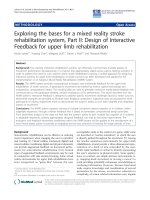
Posture recognition trials performed by the user and repre-sented by the avatarFigure 5
Posture recognition trials performed by the user and repre-
sented by the avatar.
Journal of NeuroEngineering and Rehabilitation 2005, 2:8 />Page 11 of 16
(page number not for citation purposes)
• the Server Site, where a firewall-protected central server
hosts the database described above and all the necessary
software to serve web pages dynamically generated to pro-
vide easy access to the system.
Results
All the patient management system, work-flow and
health-care service described in the previous section are
currently under test for a clinical validation and no results
on the matter is reported in the following. In the near
future, we plan to collect all the achievements deriving
from the clinical experimentation of the integration of
ULKG in the health-care service. Here, only technical
results deriving from the prototype validation, are
reported. In our laboratories, the ULKG has been submit-
ted to a series of trials in order to check the real capability
of the instrument to recognize and detect gestures, pos-
tures and movements.
The ULKG Performances as Posture and Movements
Recorder
The first basic working mode which has been tested is the
ULKG functionality as posture recorder. The system has
been used to record postures for the upper limb which
Flexion (a) and abduction (b) angles of the wrist versus timeFigure 6
Flexion (a) and abduction (b) angles of the wrist versus time. The red line is the goniometer output, while the blue one repre-
sents the ULKG response.
0 0.5 1 1.5 2 2.5
3
−15
−10
−5
0
5
10
(s)
(deg)
a
ULKG
Electrogoniometer
0 0.5 1 1.5 2 2.5
3
0
5
10
15
20
25
b
(s)
(deg)
ULKG
Electrogoniometer
Journal of NeuroEngineering and Rehabilitation 2005, 2:8 />Page 12 of 16
(page number not for citation purposes)
have been related to the corresponding configurations in
the model represented by the avatar. After having stored
all the data concerning fifty different postures in the upper
limb workspace, the same ones have been held again sev-
eral times. The output of the ULKG was visualized on a
computer screen, where the avatar replicated the subject's
posture (Figure 5). The graphical representations has been
performed by the avatar according the quaternion inter-
polation algorithm presented in section The ULKG as Pos-
ture and Movements Recorder with good animation
quality. The system recognized 100% of the postures
recorded, and no further re-calibration was thought to be
necessary even if the ULKG had been removed and re-
worn. Postures used to test the prototype included generic
positions typically seen in the workspace. This trial tested
both the hardware of the prototype and the clusterization
and reconstruction algorithms described in section The
ULKG Working Modes.
The Performances ULKG as Posture Detector
According to section The ULKG as Posture Detector the
prototype was tested through several trials to evaluate its
performances in dynamic working conditions and during
the detection of unknown posture. The main powerful
demonstration gathered from these trials is that the ULKG
is able to reconstruct postures never recorded or held
Composition of the flexion angle (in abscissa) and abduction angle (in ordinates) of the wristFigure 7
Composition of the flexion angle (in abscissa) and abduction angle (in ordinates) of the wrist. The red line is the goniometer
output, while the blue one represents the ULKG response.
−14 −12 −10 −8 −6 −4 −2 0 2 4 6
6
8
10
12
14
16
18
20
22
φ (deg)
θ (deg)
ULKG
Electrogoniometers
Journal of NeuroEngineering and Rehabilitation 2005, 2:8 />Page 13 of 16
(page number not for citation purposes)
before. In each trial the ULKG was worn by a subject and
a set of electrogoniometers was positioned on the user.
The goniometers were adequate to detect only flexion-
extension (and adduction-abduction) executed by the
joints under study and they were used only to have a
description of the movements performed. Torsions are
not relivable by using this instrumentation. The theoreti-
cal resolution provided by the producer is 0.5 degree. No
interactions between the ULKG and the goniometers were
allowed. The subject was invited to perform a set of move-
ments which involve the gleno-humeral joint, the elbow
and the wrist, like flexions-extensions, abductions-adduc-
tions and circling of the body segments. Signals deriving
from the ULKG and from the set of goniometers were
simultaneously acquired. The outputs of the ULKG was
processed according to section The ULKG as Posture
Detector and the results obtained in terms of angles were
compared with the goniometers output. Data obtained
from these experiments are showed in two different pres-
entation. The first one is a classical representation of the
angle values versus time. In the plots, both the ULKG out-
put and the values presented by the goniometers are
shown and compared. In the other representation, we
have considered some planes contained in the configura-
Extension (a) and flexion (b) angles versus time of the shoulderFigure 8
Extension (a) and flexion (b) angles versus time of the shoulder. The red line is the goniometer output, while the blue one rep-
resents the ULKG response.
0 0.5 1 1.5 2 2.5 3 3.5
4
5
10
15
20
25
30
(s)
(deg)
a
ULKG
Electrogoniometer
0 0.5 1 1.5 2 2.5 3 3.5
4
−20
−10
0
10
20
30
40
b
(s)
(deg)
ULKG
Electrogoniometer
Journal of NeuroEngineering and Rehabilitation 2005, 2:8 />Page 14 of 16
(page number not for citation purposes)
tion space 0 and we have plotted the trajectories per-
formed by some joints on them, both for goniometers
and for the ULKG. This presentation is very powerful to
detect divergences between the two responses. In Figures
6, 7 the analysis of a wrist rotation is reported. Figures 6a
and 6b show the flexion and abduction angles (which
compound the movement) versus time. The red line is the
goniometer output, while the blue one represents the
ULKG response. Figure 7 composes the two angle evolu-
tions in a trajectory which meaningfully explain the
motion. Flexion is reported on the abscissa axis, while the
abduction is reported on the axis of ordinates. The colors
used for goniometers and ULKG are the same of Figure 6.
The same scheme has been adopted to report a movement
for the shoulder in Figures 8, 9. Extension is reported in
Figure 8a (versus time) and on the y-axis of the Figure 9.
Conversely, Figure 8b and the x-axis of Figure 9 represent
the evolution of the shoulder flexion.
Finally, an elbow flexion is shown in Figures 10. Both
shoulder rotation and elbow pronationsupination have
performed qualitative results in terms of sensor signal
trends but these responses have not yet been analyzed
because the electrogoniometers we used are not capable to
detect such responses and an identification of the ULKG
along this movement direction has not been possible.
Composition of the flexion angle (in abscissa) and extension angle (in ordinates) of the shoulderFigure 9
Composition of the flexion angle (in abscissa) and extension angle (in ordinates) of the shoulder. The red line is the goniometer
output, while the blue one represents the ULKG response.
−15 −10 −5 0 5 10 15 20 25 30
0
5
10
15
20
25
30
35
φ (deg)
θ (deg)
ULKG
Electrogoniometers
Journal of NeuroEngineering and Rehabilitation 2005, 2:8 />Page 15 of 16
(page number not for citation purposes)
The results are similar to the ones demonstrated in [7].
The only difference resides in the statical character of the
trials in our previous work, while in this case movements
are described by the ULKG output. Two kinds of diver-
gence between the ULKG behavior and the goniometer
responses are pointed out by the introduced diagrams.
The first error we can note is a real divergence between the
information deriving from the two measurement systems.
Estimated trajectories differ for a certain quantity and this
phenomenon can be observed both in the plot showing
"angle versus time" and in the one showing trajectories. It
is clearly pointed out in Figure 7 in the range [-12°, -8°]
for flexion angle and [4°, 8°] for abduction angle. Evalu-
ated in cartesian norm, the error estimated is anyway
smaller than 5 per cent, if compared with the dimension
of the entire workspace. The other artifact we can note is a
difference between signals in the "angle versus time"
plots, that is not detectable by watching the other repre-
sentation. This phenomenon is due to a lack of synchro-
nization between the two measurement system and it is
manifest in Figure 8a and 8b in the [0, 0.5] second range,
without corresponding to an effective difference in terms
of trajectory, as demonstrated in Figure 9. The two systems
lead to the same results at different time. A refinement of
Flexion angle of the elbowFigure 10
Flexion angle of the elbow. The red line is the goniometer output, while the blue one represents the ULKG response.
0 1 2 3 4 5 6 7 8 9 10
0
5
10
15
20
25
30
35
40
45
50
(s)
(deg)
a
ULKG
Electrogoniometer
Publish with BioMed Central and every
scientist can read your work free of charge
"BioMed Central will be the most significant development for
disseminating the results of biomedical research in our lifetime."
Sir Paul Nurse, Cancer Research UK
Your research papers will be:
available free of charge to the entire biomedical community
peer reviewed and published immediately upon acceptance
cited in PubMed and archived on PubMed Central
yours — you keep the copyright
Submit your manuscript here:
/>BioMedcentral
Journal of NeuroEngineering and Rehabilitation 2005, 2:8 />Page 16 of 16
(page number not for citation purposes)
the movement detection algorithm may avoid these two
errors and will be studied in the future.
Conclusion
In this manuscript, an upper limb kinesthetic garment for
gesture, posture and movement detection has been pre-
sented. The main advantage introduced by this prototype
is the possibility to wear it for long periods of time thus
allowing clinicians to monitor patients without causing
any discomfort. Several issues, deriving from the employ-
ment of the new technology which has allowed the reali-
zation of the unobtrusive device, are addressed. In
particular a modeling for the physical behavior of the sen-
sor employed was proposed. An algorithm of signal anal-
ysis derived from the model was implemented to allow
the use of conductive elastomers as sensors. Moreover
both the implementation of the sensing prototype and its
performances as posture recorder and posture detector
were introduced. We used particular care in explaining all
the algorithms necessary to reconstruct or estimate pos-
ture and movement. We discussed both the application of
a the classical biomechanical methodology as well as
some innovative techniques whose development we
deemed necessary to ensure good results in the garment
employment. An application of the upper limb kines-
thetic garment as useful instrumentation in post-stroke
rehabilitation was described, together with a complete
description of the clinical service where the garment is
integrated. Finally, results on the performances of the
sensing system were reported.
Acknowledgements
This research, with particular emphasis on the post stroke rehabilitation
part, has been funded by the European Commission through MyHeart
project – IST 507816. The Authors acknowledge Dr. Alessandro Giustini,
Dr. Caterina Pistarini and Dr. Giorgio Maggioni from S. Maugeri Foundation
in Pavia, Italy for the counseling on all medical issues contained in the paper.
The Authors acknowledge Dr. Toni Giorgino from Department of Compu-
ter Engineering and Systems Science, University of Pavia, Italy for the scien-
tific and technical support.
References
1. Forster AYJ: The clinical and cost effectiveness of physiother-
apy in the management of elderly people following a stroke.
Chartered Society of Physiotherapy, Bradford Elderly Care and Rehabilita-
tion Research Department, UK 2002.
2. Krebs HI, Ferraro M, Buerger SP, Newbery MJ, Makiyama A, Sand-
mann M, Lynch D, Volpe BT, Hogan N: Rehabilitation robotics:
pilot trial of a spatial extension for MIT-Manus. Journal of Neu-
roEngineering and Rehabilitation 2004, 1(5):.
3. Post ER, Orth M, Russo PR, Gershenfeld N: Design and fabrication
of textile-based computing. IBM System Journal 2000, 39(3–4):.
4. Gregory RV, Kimbrell WC, Kuhn HH: Electrically Conductive
Non-Metallic Textile Coatings. Journal of Coated Fabrics 1991.
5. Scilingo EP, Lorussi F, Mazzoldi A, De Rossi D: Sensing Fabrics for
Wearable Kinaesthetic-Like Systems. IEEE Sensors Journal 2003,
3(4):460-467.
6. De Rossi D, Lorussi F, Mazzoldi A, Orsini P, Scilingo EP: Active
Dressware: Wearable Kinesthetic Systems. In Sensor and Sens-
ing in Biology and Engineering Edited by: Barth FG, Humphrey JA,
Secomb TW. Springer-Verlag; 2003:379-392.
7. Lorussi F, Rocchia W, Scilingo EP, Tognetti A, De Rossi D: Weara-
ble Redundant Fabric-Based Sensors Arrays for Reconstruc-
tion of Body Segment Posture. IEEE Sensors Journal 2004,
4(6):807-818.
8. Elastosil LR3162 [
]
9. Lorussi F: Analysis and synthesis of human movement: wear-
able kinesthetic interfaces;. In PhD thesis DSEA, University of Pisa;
2003.
10. Tognetti A, Lorussi F, Tesconi M, De Rossi D: Strainsensing fabric
characterization. tihrd IEEE Sensors Conference, Vienna 2004.
11. Bicchi A, Canepa G: Optimal Design of Multivariate Sensors.
Meas Sci Technol 1994.
12. Denavit J, Hartenberg RS: A Kinematic Notation for Lower-Pair
Mechanism Based on Matrices. Journal of Applied Mechanics 1955.
13. Kapandji IA: The Physiology of the Joints – the upperlimb.
Churchill Livingstone 2004.
14. Grassia FS: Practical Parametrization of Rotations Using the
Exponential Map. Journal of Graphics Tools 1998, 3(3):.
15. P Baerlocher RB: Parametrization and range of motion of the
ball-and-socket joint. Proceedings of the IFIP TC5 WG5.10 DEFORM
2000 Workshop and AVATARS 2000 2001.
16. Shoemake K: Animating rotations with quaternion calculus.
ACM SIGGRAPH 1987.
17. The Stroke Prevention and Educational Awareness Diffusion
(SPREAD): The Italian Guidelines for stroke prevention. Neurol
Sci 2000, 21:5-12.