báo cáo hóa học: " A biologically inspired neural network controller for ballistic arm movements" ppt
Bạn đang xem bản rút gọn của tài liệu. Xem và tải ngay bản đầy đủ của tài liệu tại đây (851.4 KB, 17 trang )
BioMed Central
Page 1 of 17
(page number not for citation purposes)
Journal of NeuroEngineering and
Rehabilitation
Open Access
Research
A biologically inspired neural network controller for ballistic arm
movements
Ivan Bernabucci*
1
, Silvia Conforto
1
, Marco Capozza
2
, Neri Accornero
2
,
Maurizio Schmid
1
and Tommaso D'Alessio
1
Address:
1
Dipartimento di Elettronica Applicata, Università degli Studi "Roma TRE", Roma, Italy and
2
Dipartimento di Scienze Neurologiche,
Università "La Sapienza", Roma, Italy
Email: Ivan Bernabucci* - ; Silvia Conforto - ; Marco Capozza - ;
Neri Accornero - ; Maurizio Schmid - ; Tommaso D'Alessio -
* Corresponding author
Abstract
Background: In humans, the implementation of multijoint tasks of the arm implies a highly complex
integration of sensory information, sensorimotor transformations and motor planning. Computational
models can be profitably used to better understand the mechanisms sub-serving motor control, thus
providing useful perspectives and investigating different control hypotheses. To this purpose, the use of
Artificial Neural Networks has been proposed to represent and interpret the movement of upper limb. In
this paper, a neural network approach to the modelling of the motor control of a human arm during planar
ballistic movements is presented.
Methods: The developed system is composed of three main computational blocks: 1) a parallel
distributed learning scheme that aims at simulating the internal inverse model in the trajectory formation
process; 2) a pulse generator, which is responsible for the creation of muscular synergies; and 3) a limb
model based on two joints (two degrees of freedom) and six muscle-like actuators, that can accommodate
for the biomechanical parameters of the arm. The learning paradigm of the neural controller is based on
a pure exploration of the working space with no feedback signal. Kinematics provided by the system have
been compared with those obtained in literature from experimental data of humans.
Results: The model reproduces kinematics of arm movements, with bell-shaped wrist velocity profiles
and approximately straight trajectories, and gives rise to the generation of synergies for the execution of
movements. The model allows achieving amplitude and direction errors of respectively 0.52 cm and 0.2
radians.
Curvature values are similar to those encountered in experimental measures with humans.
The neural controller also manages environmental modifications such as the insertion of different force
fields acting on the end-effector.
Conclusion: The proposed system has been shown to properly simulate the development of internal
models and to control the generation and execution of ballistic planar arm movements. Since the neural
controller learns to manage movements on the basis of kinematic information and arm characteristics, it
could in perspective command a neuroprosthesis instead of a biomechanical model of a human upper limb,
and it could thus give rise to novel rehabilitation techniques.
Published: 3 September 2007
Journal of NeuroEngineering and Rehabilitation 2007, 4:33 doi:10.1186/1743-0003-4-33
Received: 22 May 2006
Accepted: 3 September 2007
This article is available from: />© 2007 Bernabucci et al; licensee BioMed Central Ltd.
This is an Open Access article distributed under the terms of the Creative Commons Attribution License ( />),
which permits unrestricted use, distribution, and reproduction in any medium, provided the original work is properly cited.
Journal of NeuroEngineering and Rehabilitation 2007, 4:33 />Page 2 of 17
(page number not for citation purposes)
Background
Human beings are able to accomplish extremely complex
motor tasks in all kinds of environments by means of a
highly organized architecture including sensors, process-
ing units and actuators. From a cognitive and develop-
mental perspective, and a rehabilitation standpoint, it is
necessary to fully understand the complex interactions
between the controller (the Central Nervous System) and
the controlled object (all parts of the body)[1]. These
interactions describe the process of motor control for
which many theories have been developed. As far as the
generation of motor commands is concerned, in literature
it is generally acknowledged that nervous system gener-
ates motor commands based on internal models able to
take account of the kinematics and the dynamics of the
biomechanical structures [2-4]. These models can be
described as groups of neural connections that intrinsi-
cally contain information about biomechanical proper-
ties of the human body in relation both to the
environment and the subject's experience.
However, the mechanisms underlying the generation and
organization of these neural models are still object of con-
troversy [5]. In order to interpret their functions, in litera-
ture different computational approaches to simulate both
the biomechanical structure and the controller have been
presented for a 2D [6] framework.
In this context, there is an interest in the use of Artificial
Neural Networks (ANN) because of their capabilities to
adapt and to generalise to new situations. In order to link
the neural learning/adaptation processes to their artificial
replica, ANN have been used in some studies regarding
neurophysiologic simulations. However, most of these
ANN imply the presence of a supervisor that uses sensory
information in order to minimize the error related to the
motor task [7]. This methodology, commonly imple-
mented on forward multilayer networks with retrospec-
tive learning (back propagation), is efficient from an
operative standpoint, but not completely plausible as a
biologically inspired learning model of motor control, at
least for the presence of a teacher who is pre-existent to the
organization of the system.
To overcome this drawback, neural models using unsu-
pervised training techniques for the exploration of motor
spaces have been proposed [8] thus meeting the features
of self-organization typical of internal representations.
The adaptability of the neural model together with the
unsupervised training can also answer to environmental
modifications such as those represented by external force
fields and haptic distortions. Following this approach, it is
of interest to study models able to simulate motor control
mechanisms in terms of both generating and managing
the sequence of motor commands that enable the arm to
execute movements in the space. In this paper the focus is
on the execution of ballistic movements.
According to the work of Karniel and Inbar [9], ballistic
movements can be studied considering that: 1) there is no
visual information; 2) any single movement is ballistic. As
for every voluntary movement, the central nervous system
must address three main computational problems: 1)
determination of the desired trajectory in the visual coor-
dinates; 2) transformation of the trajectory from visual to
body coordinates; 3) generation of motor commands
[10]. The lack of visual information and the ballistic
nature prevent to have a feedback on the controller
[11,12]: in fact, the delay introduced by a proprioceptive
feedback in a biological system is too large to permit on-
line corrections of the trajectories, and other studies [13]
state that motor commands could be adjusted online
without the need to involve a conscious decision process.
In any case, the commonly accepted idea is that ballistic
movements can be managed by feed-forward controllers
without using visual information as feedback. Some com-
mon characteristics are generally shared by ballistic move-
ments on a plane, and these are: roughly straight
pathways and bell-shaped hand speed profiles [14,15].
Moreover, point to point movements have been studied
following the hypothesis known as the minimum vari-
ance rule, able to attain physiological kinematic results as
Fitt's Law and 2/3 Power Law [16]. Some authors [17,18]
tried to provide a mathematical explanation of these kin-
ematic invariants suggesting the hypothesis that the cen-
tral nervous system aims at maximizing the smoothness
of the movement.
In this work, ballistic movements will be controlled by an
ANN controller that can be defined as "biologically
inspired". It will be able to generate muscular activations
knowing only the starting and arrival points of each
movement, giving rise to a solution for the inverse
dynamics problem (that is determining muscular forces
on the basis of kinematic information). The muscular acti-
vations will generate ballistic movements having charac-
teristics similar to human movements. This biologically
inspired model will integrate an ANN, which should
accomplish the task on the basis of its adaptability and
plasticity [19,20], together with a biomechanical arm
model, considered as a 2 DOF system, in order to simulate
the behaviour of an end-effector driven by the sequences
generated by the controller.
In the first part of this work, materials and methods will
be reported: after a description of the parallel distributed
computational system that has been used, the generator of
the neural input commands and the biomechanical
Journal of NeuroEngineering and Rehabilitation 2007, 4:33 />Page 3 of 17
(page number not for citation purposes)
model of the arm will be presented. Finally, the evalua-
tion tests and the obtained results will be discussed.
Methods
In this section we describe the general scheme of the pro-
posed model, which can be divided into three main mod-
ules, each one with a specific functionality in the
transformation process from perception to motor action,
that is: the perception task, the elaboration of data and the
motor activation. Therefore, two computational blocks
simulate the motor control of the upper limb, while a
third block is responsible for the modelling of the actua-
tor.
The first module is devoted to processing spatial informa-
tion in order to solve the inverse dynamics problem (i.e.
which neural signals, that is which forces, have to be gen-
erated to reach a specific point in the environment?). The
strategy can be acquired after a series of synaptic modifi-
cations that represent the construction of the internal
model both in architectural and functional ways. The
whole process, that simulates the generation of the inter-
nal models by means of synaptic modifications, is called
learning. It must be emphasized that, since the main pur-
pose of the present work is to characterize a model simu-
lating the generation and the actuation of ballistic
movements, no online feedback on the position error is
present in the scheme. We deal, in fact, with a process
where the learning scheme modifies the neural features in
order to map the working space and reach the desired tar-
gets. Even if the learning scheme can be considered as a
functionality of the Neural System, a separate paragraph
in the Materials and Methods section has been devoted to
the explanation of the learning process in order to outline
the processing scheme adopted.
The second module is called Pulse Generator, and it essen-
tially generates the motor signals necessary for to activate
the muscles and to consequently produce the movements
of the arm model.
The third module simulates a simplified version of the
biomechanical arm model. In fact, the human arm
presents a high number of degrees of freedom and a
redundancy due to the difference of dimensions between
muscular activations space and working space (that is the
whole set of the points attainable by the arm model), so
that the set of available ways to accomplish a specific task
is not unique. In the model, only two mono-articular
pairs of muscles for each joint (elbow and shoulder) and
a bi-articular pair of muscles connecting the two joints
have been taken into account. The first agonist-antagonist
pair acts across the shoulder joint: the pectoralis major is
the flexor, while the deltoid is the extensor. The second
pair acts across the elbow joint: the long head biceps bra-
chialis is the flexor, while the lateral head triceps brachia-
lis is the extensor. The third pair of muscles links both the
joints: the flexor is the biceps brachialis short head and
the extensor is the triceps brachialis long head.
From the results that will be presented below, it emerges
that, even in this simplified version, the synthesized sys-
tem is able to execute accurate planar movements.
The proposed Model
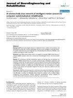
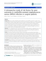
Figure 1 shows a diagram of the entire model involving
the cascade of the three modules.
The first module has been structured as a Multi Layer Per-
ceptron with an architecture composed by 4 layers. The
design process of the neural network used for this study is
based on the analysis of the behaviour of various neural
structures in responding to a same training and testing set.
In order to choose the most adequate structure, different
types of neural networks have been considered and
trained: a first group with only one hidden layer (varying
the number of neurons), and a second group with two
hidden layers (varying the number of neurons in different
combinations for each layer). Experimental results con-
sidering the errors with respect to the training set and to
Diagram of the modelled motor control chainFigure 1
Diagram of the modelled motor control chain. The task is executed by the three modules, while no feedback connec-
tion is present.
Journal of NeuroEngineering and Rehabilitation 2007, 4:33 />Page 4 of 17
(page number not for citation purposes)
the testing set as cross-validation (in order to avoid over-
fitting problems) led us to choose an ANN design with
two hidden layer of 20 neurons each.
The input layer is therefore defined by 4 input units,
which correspond to the coordinates of the starting and
final positions of the movement.
More specifically, the first 2 units are related to the infor-
mation on the initial position of the trajectory, while the
other 2 units are related to the desired final position. The
output layer has 4 units, because the neural network gen-
erates one value of timing for each of the three muscular
pairs related to shoulder and elbow, plus one value shared
by all the muscular pairs, as in fig. 2: TcoactShoulder,
TcoactElbow, TcoactBiarticular, Tall, respectively. More
specifically:
• for the shoulder, when the agonist muscle is activated,
the movement starts. After a time interval, defined by the
ANN, the antagonist is activated, so that the time interval
TcoactShoulder is characterized by the co-activations of
the agonist and antagonist (mono-articular) muscles of
the shoulder joint (i.e. simultaneous presence of the neu-
ral inputs for shoulder muscles); its sign defines which
muscle (i.e. agonist or antagonist) is activated first;
• for the elbow, TcoactElbow has the same function of
TcoactShoulder;
• for the muscle pair that connect the two joints, Tcoact-
Biarticular has the same function of TcoactShoulder and
TcoactElbow.
• the movement duration is Tall: it represents the total
duration of the neural activation, thus affecting the whole
movement of the arm. This output value is constrained in
the range 300 ms – 1 s. The time range has been chosen in
order to let the limb model reach every sector of the work-
ing plane, while maintaining the ballistic characteristics of
the movement.
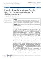
Figure 2 depicts the profile of these neural activations hav-
ing rectangular shapes, and shows the duration of the
entire voluntary task ranging in the interval 300 ms and 1
s.
The transfer function chosen for every unit is the well
known hyperbolic tangent ,
n
e
i
m
wn
j
m
j
N
m
j
m
=
+
∑
−
−⋅
−
=
−
2
1
1
1
0
1
Neural activations of the shoulder, the elbow and the biarticular muscle pairFigure 2
Neural activations of the shoulder, the elbow and the biarticular muscle pair. T
all
, total time of neural activations, is
the same for all the muscles; the three T
coact
represent the interval of co-activation of flexor and extensor muscle. The value of
1.5 s in the abscissa is the total observation time.
Journal of NeuroEngineering and Rehabilitation 2007, 4:33 />Page 5 of 17
(page number not for citation purposes)
where the output n
i
m
of the i
th
neuron at the m
th
layer is
obtained from the weighted outputs of the (m - 1)th level.
The values generated by the output layer, from now on
indicated as neural outputs p, are bounded between -1
and 1, and are used by the Pulse Generator.
The system, in the present version, allows having only
biphasic activation patterns for each muscle pair. Thus,
the interval delimited by the initial point of the pattern
and the TcoactShoulder, the TcoactElbow and the Tcoact-
Biarticular values correspond to the Action Pulse, i.e. the
time in which the neural activations of the agonist muscle
determine an activation in the EMG signal, while the one
going from this value till the end of the pattern, i.e. the
time in which the neural co-activations of the antagonist
muscle determine a braking burst in the EMG signal [21],
corresponds to the Braking Command. The range of these
intervals, including the co-activation time of the shoulder
and the elbow muscles, together with the whole duration
of the activations, establishes the direction, length and
curvature of the movements.
The neural outputs p need to be transformed in order to
be utilized as commands for the muscles like mechanical
actuators. Here the second module (i.e. the Pulse Genera-
tor) comes into play: its main purpose is to generate the
pulse train shape, by analyzing and elaborating p. This
pulse train should simulate the efferent commands given
to the motor neurons, and thus to the biomechanical
model of the arm. The third module in fig. 1 corresponds
to a biomechanical model of an upper limb, composed of
a skeletal structure together with a muscular structure. The
skeletal model has a plant structure composed of two seg-
ments (because the wrist joint is not considered), with
lengths l
1
and l
2
, which represent the forearm and the
upper arm respectively, connected through two rotoidal
joints (figure 3). The planar joints that connect the two
segments can assume values (q
1
and q
2
) in the angular
range [0,
π
]. These values can be put in correspondence
with the Cartesian coordinates of the free end in the work-
ing plane by means of direct kinematic transformation
(equation 2).
The muscular system is thus based on 6 muscle-like actu-
ators, and establishes the dynamic relationship between
the position of the arm and the torques acting on each sin-
gle joint.
Body segment anthropometrics and inertias of both upper
arm and forearm are obtained from the scientific literature
[22], taking into account the specific body height and
weight. Table 1 shows the values of the inertias adopted in
the muscular-skeletal system.
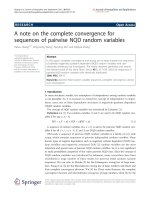
Following the work of Massone and Myers [1], each mus-
cle is synthesized with the non-linear Hill-type lump cir-
cuit [23] as depicted in figure 4.
According to the notation present in [9], the neural out-
puts serve as inputs for the actuator, resulting in a time
function called F
0
representing the muscle tension. The
Hill model is composed of a series elastic element (SE), a
parallel viscous element (PE) and a contractile element
(CE) which includes the non-linear viscosity B depending
on the shortening velocity ν, as in equation 3
where a, b and a' are constant parameters (whose meas-
urement units are respectively a = [m
-1
], b = [rad/s] and a'
= [a/b]) and T
0
is the value of the torque applied by the
single muscular unit as a percentage of the maximum iso-
metric force associated to that muscle (T
0
= Fmax*F
0
*d,
where d is the average moment arm, Fmax is the maxi-
mum isometric force associated to that muscle and F
0
is
the percentage coefficient), thus resulting in a different
behaviour of the contractile element when shortening or
lengthening. Table 2 shows the numerical values of the
parameters of the Hill's model.
The force difference between the muscles of each single
joint is implemented on the actuators by means of differ-
xl q l q q
yl q l q q
=⋅ +⋅ +
=⋅ +⋅ +
12
12
112
112
cos( ) cos( )
sin( ) sin( )
(1)
B
aT b v
aT
v
v
aa b=
⋅+
⋅
≤
>
== =
()/()
’
’,
0
0
0
0
41
(3)
Table 2: Numerical values of the Hill's parameters
Parameter Units
Kse 120 N/rad
Bpe 30 N.s/rad
Fmax(shoulder) 800 N
Fmax(elbow) 700 N
Fmax(double joint) 1000 N
Table 1: Numerical values of the parameters of the arm
Parameter Units
M – Mass of the subject 80 kg
M1 – mass of the upper arm 2.24 kg
M2 – mass of the lower arm 1.92 kg
L – height of he subject 1.70 m
l1 – length of the upper arm 0.297 cm
l2 – length of the lower arm 0.272 m
I1 – inertias of the upper arm M1*(0.322*L1)
2
I2 – inertias of the lower arm M2*(0.468*L2)
2
Journal of NeuroEngineering and Rehabilitation 2007, 4:33 />Page 6 of 17
(page number not for citation purposes)
ent maximal amplitudes of the corresponding forces. The
values of the forces are related to maximal values that are
represented in Table 2. Then the effects of the correspond-
ing torques thus obtained are then summed in order to
obtain the overall torques on each joint
τ
1
and
τ
2
, as in
Equation 4:
where Φ = 0.6 and
ϕ
= 0.4 are non dimensional units and
the F values in the equation are the values of the torque
applied by each muscle of the corresponding joint during
flexion or extension.
Finally, the trajectory in the working plane is obtained
from a double integration at each sampling time of the
acceleration of the end point of the effector due to the
changes in the overall torque applied to both joints.
The Learning Paradigm
One key point of the present work is the training para-
digm adopted for the neural controller with the aim of
defining a specific internal model during ballistic move-
ments of the arm, that is to establish a mapping between
the desired movements within the working plane and the
necessary neural outputs, so that the controller could
learn the inverse dynamics of the biomechanical arm
model. The algorithm will adapt the neural weights and
biases so that, if the 4 inputs of the network respectively
correspond to the coordinates of the starting point [q
1
,
q
2
], and of the desired target [q
1
d
, q
2
d
], then the output of
the net will approach the correct p.
More precisely, as shown in the scheme depicted in figure
5, the output p of a non-trained network (phase 1) can be
the input for the biomechanical arm model (phase 2): this
input leads to the execution of a reaching movement in
general different from the desired one, that is towards a
different target. These neural inputs p, together with the
starting and ending points coordinates, become the new
data for the training of the network (phase 3). In this way,
a mapping between muscular activations and points of
the working space can be attained.
The key feature of this approach is that the position error
in executing the movements is not used in the training.
The reason is that, following the studies of [20] a super-
vised training mechanism for the controller must be
excluded, thus meaning that the knowledge of the posi-
tion error made in carrying out the movement will not be
used to train the neural network. The exclusion of a feed-
back circuit both in the phases of learning and executing
the task, reflects the capacity of the motor control system
to explore the workspace either without basing itself on
pre-existent information (batch supervised training) or
elaborating the data coming from the environment (feed-
back error learning). In the learning phase of the network,
the association: "starting point – neural inputs generating
the movement from the starting point to an ending point"
is therefore used. This is the step-by-step procedure in
which the controller learns to make different movements.
τφφ
τϕ
11 1 3 3
22 2 3
=−+⋅−⋅
=−+⋅
−− − −
−−
FF F F
FF F
flex ext flex ext
flex ext −−−
−⋅
flex ext
F
ϕ
3
(4)
Hill's muscle modelFigure 4
Hill's muscle model. The force F applied on the joint
depends on SE, the series elastic element, PE, the parallel vis-
cous element, and CE, that is the contractile element, defined
by the neural input processor (NIP) and a viscous element
B(ν) where ν is the shortening velocity of the muscle.
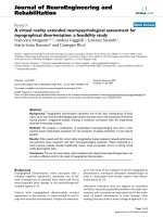
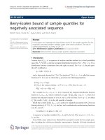
Biomechanical model of the upper limbFigure 3
Biomechanical model of the upper limb. The two seg-
ments L
1
and L
2
represent the arm and the forearm. From
the angular values q
1
and q
2
it is possible, by means of direct
kinematics, to obtain the Cartesian position of the wrist
within the working plane. The effect of gravity force is not
considered in the model.
Journal of NeuroEngineering and Rehabilitation 2007, 4:33 />Page 7 of 17
(page number not for citation purposes)
It is important to stress again that, unlike most of the
models proposed in the literature, this controller learns
the movement actually carried out, not the wanted one.
This training strategy recalls the big picture of the classical
Piagetian's concept of motor development. More in par-
ticular it can be considered as leading the way to the circu-
lar reaction learning model. Otherwise, in the proposed
scheme, the construction of the inverse dynamics of the
arm within a particular environment neglects the inter-
connection between the eye and the arm systems, but is
driven by a purely proprioceptive exploration phase out-
lining the development of an internal model. During the
training phase, the neural controller tends to achieve an
optimal behaviour in reaching a desired target point by
improving the correlation between the sensory map (start-
ing and ending point) and the motor map (muscular acti-
vations which generate the movement between these two
points) through the entire working plane. The reduction
of the error on the final position can be thus considered as
a consequence and not a cause of the learning procedure.
The proposed neural model, basing on the philosophy
architecture of Direct-Inverse Model (Jordan, 1995),
shows novel and innovative characteristics.
Simulating the Internal Model: the training phase
During the training, the system automatically and ran-
domly chooses the starting and ending points of the
movements, which in turn determine the parameters p to
be used in the Pulse Generator.
In addition, during the training a random noise generator
acts on the output of the neural network in order to pre-
vent convergence on local minima, which would imply a
limitation in direction or amplitude of upper limb move-
ments.
In fact, especially for the very first period of exploration, is
it possible to have small variations in the weights of the
neural controller. This could possibly bring the neural
network to converge to a local minimum state, where the
weights are not optimally calibrated to face the problem
of the arm control. For this reason, the noise generator
intervenes on the output parameters p of the neural con-
troller with a probability exponentially decreasing with
the number of overall movements (see figure 6).
In the initial phases of the training, the controller is not
trained, and there is no correspondence between the
desired target and the one actually reached by the move-
ment of the biomechanical model of the arm. At the end
of each task, a standard back-propagation algorithm with
momentum is used for the training and thus the variation
of the weights.
The training of the artificial neural network and the com-
plete coverage of the working plane, with respect to both
the possible starting and target points, can be reached
with about 200.000 random generations (epochs). The
decision about the end of the training is not based on a
prefixed number of movements/training steps but on the
monitoring of the convergence of the network.
Once the neural controlled is trained, the overall system is
tested and the behaviour is analyzed. In this second phase,
the noise generator is not active. Even if the inputs driving
Learning scheme of the proposed modelFigure 6
Learning scheme of the proposed model. The noise is
added to the neural input generated by the controller. The
new vector n
i
is thus used for the generation of the muscular
activities and for the controller training process.
Diagram of the exploration and the learning processFigure 5
Diagram of the exploration and the learning process.
(1) The arm starts in the position defined by the angle q
1
and
q
2
(Cartesian position x
s
, y
s
), while the desired target position
is defined by q
1
d
and q
2
d
(Cartesian position x
d
and y
d
). The
angles q
1
' and q
2
' univocally define the spatial configuration of
the arm in the arrival point (Cartesian position x
a
, y
a
) (2),
that in the early phases of the learning process is different
from the desired one: the ANN learns the association
between the starting point and the arrival point (3).
Journal of NeuroEngineering and Rehabilitation 2007, 4:33 />Page 8 of 17
(page number not for citation purposes)
the network are different from those used in the training
phase, the generalization capabilities of the connectionist
system enables it to operate correctly.
Simulating the Internal Model: Testing the performance of
the model
Tests, and comparisons with results available in literature
have been performed in order to evaluate the performance
of the model after the convergence of the network.
The neural controller has been tested by presenting a high
number of pairs of randomly chosen start-target points,
and the errors in reaching the target have been recorded.
Initially, in order to qualitatively test the behaviour of the
controller, a set of 1000 movements starting from the
same initial point have been considered. This set have
been used to analyze the capacity to cover the entire work-
space, to give a graphical representation of the correlation
of the error position with respect to the length of the
movements and to observe the distribution of the peak
velocity within the working plane.
Furthemore,1200 random movements ranging from 5 cm
to 60 cm, subdivided into groups spaced out by 5 cm (200
movements per group), have been generated, in order to
make a comparison with the kinematic analysis of ballis-
tic arm movements presented in literature (such as in
[8,14,24]), where movements with a maximum ampli-
tude of ± 30 cm have been examined. This subset has been
defined Physiological Subset (PS). The characteristics of
these tasks have been analyzed and compared to the data
obtained from experimental tests on human beings, car-
ried out in [8,24]. In the latter paper, indexes useful to
quantitatively determine some characteristics of the
movements have been calculated.
The accuracy of the neural network in implementing the
movements has been characterised by means of the fol-
lowing parameters:
• The absolute position error of the arrival position
reached by the end-effector with respect to the desired
final position (or target).
• The module error (the amplitude error).
• The phase error (the error pointing at the target).
• The curvature.
• The velocity curve.
The position and phase errors have been chosen in order
to reveal the presence of a biased behaviour. In particular,
the module error |e| has been defined as the difference
between the segment connecting the starting point and
the arrival point (x
a
, y
a
) and the straight line from the
starting point to the target (x
t
, y
t
).
The phase error ∠e (∆
ϕ
) has been defined as the difference
of the angles which identify the two lines connecting the
starting point with respectively the target and the arrival
point, and it has been used to determine if the neural con-
troller was able to correctly point at the target. The pair of
error parameters are graphically explained in figure 7.
For the curvature, there are various definitions in the liter-
ature. The index of curvature of a movement, C, is defined
in [24] as the ratio between the curvilinear abscissa and
the minimum Euclidean distance between the starting
and the arrival point.
C
dx dy
xx yy
ii
i
N
fs fs
=
+
−
()
+−
()
=
−
∑
22
1
1
22
(5)
Module and Phase ErrorFigure 7
Module and Phase Error. Considering the movement
directed from the starting point (x
p
, y
p
) to the arrival point
(x
a
, y
a
), the module error (or amplitude error) |e| is the dis-
tance between (x
tp
, y
tp
) and (x
a
, y
a
); the phase error (or the
direction error) is the angular difference between the seg-
ment connecting (x
p
, y
p
) and (x
t
, y
t
) and the segment con-
necting (x
p
, y
p
) and (x
a
, y
a
).
Journal of NeuroEngineering and Rehabilitation 2007, 4:33 />Page 9 of 17
(page number not for citation purposes)
where the numerator represents the amplitude of the
movement carried out, while the denominator is the min-
imum distance between the starting point and the arrival
point. This is defined as the Normal Curvature (NC). In
[25,26], two curvature indexes are used: the first is the
ratio between the distance from the medium point of the
straight line connecting the starting (A) and the arrival
point (B) and the trajectory performed by the subject
(medium curvature: MdC), while the second considers the
maximum value of all the distances from the points defin-
ing the trajectory and the straight line defining the mini-
mum distance from the two extremities of the path
(maximum curvature: MxC). In [27] the measure of curva-
ture is obtained from MxC, by replacing the maximum
value with the mean value (total curvature: TC). Figure 8
graphically describes these differences.
The coefficient of variation (CV), defined as the ratio
between the standard deviation and the mean error posi-
tion has also been evaluated. The distribution of the neu-
ral activation times with respect to the length of the
movements has been taken into account.
Finally, the performance of the model with respect its pos-
sibilities of adapting to modifications in the environment,
such as the presence of disturbing force fields, has been
taken into account. To this purpose, a force proportional
to the movement speed and directed along the horizontal
axis has been inserted in the model, after the training for
unobstructed movements in all the working plane. The
additional training necessary to the model to be able to
cope with this force and the performance as for the reach-
ing errors have been evaluated.
Results and Discussion
The proposed neural system is able to achieve a complete
coverage of the working plane, unlike other models [9]
which are limited to short amplitude motor tasks, usually
around 20–30 cm.
This feature can be appreciated in figure 9 where, for visu-
alization purposes, the same starting point and 1000 tar-
get points have been considered.
Curvature IndexesFigure 8
Curvature Indexes. The figure shows the 4 indexes taken into account: the Normal Curvature (NC) is the ratio between
the length of the trajectory executed (L) and the straight line connecting the starting point and the arrival point (h). The Maxi-
mum Curvature is the maximum distance (d) between L and h. The Medium Curvature is the distance (d) between L and h
evaluated in h/2. In the end the Total Curvature is the mean value of all the distances d between L and h.
Table 3: Mean values of the curvature indexes for the set of
movements
Normal Curvilinearity NC 1.09
Maximum Curvilinearity MxC 0.63 cm
Medium Curvilinearity MdC 0.61 cm
Total Curvilinearity TC 0.16 cm
Journal of NeuroEngineering and Rehabilitation 2007, 4:33 />Page 10 of 17
(page number not for citation purposes)
Figure 10 shows two different movements starting from
the same point, together with the neural outputs p and the
relevant velocity profiles.
The first movement of the set simulates the role of the Pec-
toralis Major, in the shoulder joint, for targets positioned
in a position west with respect to the starting point, while
the second one implies the use of the Deltoid for the target
allocated in a position east with respect to the starting
point. The velocity profile reflects the bell shaped behav-
iour typically found in literature (see e.g. [14]).
Figure 11 shows that even when changing the starting
point, the relations between the direction of the move-
ment and the neural inputs persist.
For the PS, the mean position error has been of about 4.8
cm with a standard deviation of about 4 cm. Figure 12
shows the histogram of the percentage of the absolute
position error with respect to the length of the movement.
The mean absolute error, normalised with respect to the
length of the movements, resulted always lower than
0.27. These findings show that the model is able to accu-
rately simulated ballistic (unobstructed) movements of
the arm.
The module error shows a value of 0.51 cm., as illustrated
by Figure 13. The mean value of the angular error, pre-
sented in figure 14, resulted almost negligible, thus show-
ing that the ANN gives unbiased results, that is it is able to
correctly point (in the average) at the target with limited
(in the average) errors.
Moreover, in figure 15 it is possible to see that the mean
absolute position error has a limited variation with the
increase of the movement length.
When analysing the CV of the movements in PS it is pos-
sible to observe that monotonically increases ranging
from 0.6 to 0.8. This behaviour can be explained by con-
sidering that when the movement becomes longer the pre-
cision in reaching the target decreases and the position
error distribution increases. A comparison between the
experimental data reported in [24,26] and the data
extracted from the simulated model of the present work is
interesting because it puts in evidence the behaviour of
the proposed neural model for as what concerns the cur-
vature.
To compare our results with the data in the literature, the
four values of curvature have been taken into account. The
table 3 shows the mean values of NC, MxC, MdC and TC).
The mean value of NC reported in [28] is about 1.02, for
movements with a maximum amplitude of 42 cm, while
in this system the mean value is 1.06.
Two main things must be stressed out:
• even if the biomechanical arm model is only an approx-
imation of a real upper limb structure, in which further
Distribution of the targets reached within the working planeFigure 9
Distribution of the targets reached within the working plane. The starting point is indicated with the circle mark. It is
possible to observe an almost complete coverage of the area.
Journal of NeuroEngineering and Rehabilitation 2007, 4:33 />Page 11 of 17
(page number not for citation purposes)
Example of two movements carried out by the arm model guided by the trained neural controller starting from the same initial positionFigure 10
Example of two movements carried out by the arm model guided by the trained neural controller starting
from the same initial position. The starting point is the same for the 2 tasks (coordinates: x = -0.2; y = 0.2); the arrival
points have been chosen in 2 different symmetric positions with respect to the starting point, at a distance of about 22.4 cm.
Each row represents a different movement. The left column of this image depicts the trajectory followed by the wrist. The cen-
tral column shows the neural inputs necessary for the motor commands of the flexor and extensor muscles acting on both the
shoulder and the elbow joint. The right column shows the wrist velocity profile.
Example of two movements carried out by the arm model guided by the trained neural controller starting from different initial positionsFigure 11
Example of two movements carried out by the arm model guided by the trained neural controller starting
from different initial positions. The two tasks start from different points, and point towards different directions within the
working plane. In the upper row, the central column shows the neural commands of the muscle pair of the shoulder and of the
elbow joint necessary for the trajectory presented in the left column. The movement starts at the point [-0.4; 0.35] while the
target point is at [-0.2; 0.2]. In the lower row, the right column shows the wrist velocity profile for the second movement
whose starting point is at [-0.2; 0.3] and whose target point is at [-0.2; 0.1].
Journal of NeuroEngineering and Rehabilitation 2007, 4:33 />Page 12 of 17
(page number not for citation purposes)
muscle activations have an influence, even if minor, on
the overall movement, the results are very interesting.
• all the experiments on human subjects from the litera-
ture are replications of the same set of movements in dif-
ferent direction or with different amplitude; this brings a
specialization of the tasks during the trials and therefore
to lower errors.
In [26,29] the normalized maximum curvature shows a
value of about 0.05 ± 0.02. This result has been estimated
as the ratio between the maximum distance from the
straight line connecting the starting and the arrival point
(that is the value MxC of the present system) and the
length of straight line connecting them; moreover the val-
ues reported are related to tasks performed on the sagittal
plane.
Figure 16 depicts a bi-dimensional projection of the error
for the wrist final position when implementing 1000 test
movements, with the same starting point. Taking off the
outliers (which are the movements that show a ratio
between final error position and length of the desired task
greater than 27%), the results considering only one start-
ing point and movements with a maximum amplitude of
60 cm show a mean error position value of about 2.4 cm
with a standard deviation of 1.8 cm (it is possible to see
that the behaviour is quite uniform, even if there are some
error peaks far from the starting point that can justify a
correlation different from zero).
Module ErrorFigure 13
Module Error. The figure shows the trend of the module error (or amplitude error) with respect to the movements included
in the subset analyzed. It is possible to observe that the mean value is close to zero, thus proving an unbiased behaviour.
Histogram of the percentage error positionFigure 12
Histogram of the percentage error position. Histo-
gram of the percentage error position (PE, that is the abso-
lute position error with respect to the length of the
movement carried out) of the end effector of the upper limb
with respect to the number of movements analyzed.
Journal of NeuroEngineering and Rehabilitation 2007, 4:33 />Page 13 of 17
(page number not for citation purposes)
Phase ErrorFigure 14
Phase Error. The figure shows the trend of the phase error (or direction error) with respect to the movements included in
the subset analyzed. Also in this case the mean value is negligible.
Dispersion of the error with respect to the length of the movementsFigure 15
Dispersion of the error with respect to the length of the movements. It is possible to observe a monotonic increase
of the mean position error value with respect to the length of the movement. The vertical bars represent the value 2*STD.
Journal of NeuroEngineering and Rehabilitation 2007, 4:33 />Page 14 of 17
(page number not for citation purposes)
Figure 17 shows the behaviour of the velocity profile
whose peak value, when considering the movements start-
ing from the same point, increases accordingly with the
length of the movements. From the model it has been
possible to evaluate the presence of the "scaling effect"
which explains the invariant property of the wrist velocity
profile: when the length of the movement increases, so
does the maximum velocity reached along the trajectory
while maintaining the same profile.
Figure 18 shows that the velocity curve maintains the
same profile for shorter and larger movements, and that
Comparison between wrist velocity profileFigure 18
Comparison between wrist velocity profile. The figure
shows the wrist velocity profiles of two different movements
starting from the same initial point, directed towards the
same direction but with different amplitudes. Shorter move-
ment is related to the slower velocity profile (the blue one).
Distribution of the absolute error position within the working planeFigure 16
Distribution of the absolute error position within the working plane. The figure shows that higher values are mostly
present along the borderline of the working plane.
Graph of the scale effectFigure 17
Graph of the scale effect. The figure shows the distribu-
tion of the wrist peak velocity with respect to the distance
from the starting point. It is possible to observe a uniform
increase of the peak velocity from the area near the starting
point to the borders of the working plane.
Journal of NeuroEngineering and Rehabilitation 2007, 4:33 />Page 15 of 17
(page number not for citation purposes)
the duration of the movements does not increase linearly
with their length. These findings are similar to those
present in [14,23].
Moreover, similar activations bursts are associated to sim-
ilar movements: i.e. it is possible to see that in movements
directed towards the same area inside the working plane,
not only the same muscles of the shoulder and the elbow
joint are activated first, but also the intervals of the neural
activations of these muscles show the same duration. This
finding can be correlated with a feature that could be
defined as a global isochrony of the movements. In Figure
19 the value of the total activation time of activation with
respect to length of the movement is shown. It emerges
that the time spent increases, though not proportionally,
to the length of the movement.
Finally, we simulated the insertion of the model in a force
field, proportional to the movement speed, with a peak
amplitude up to 15 N and directed along x axis, which acts
on the already trained controller. The additional training
needed by the model to be able to cope with this force
required only the 1% of the epochs necessary for the train-
ing all over the working plane for unobstructed move-
ments. It resulted that the model learned to deal with this
force by modifying the activation intervals of the muscles,
thus increasing the stiffness of the arm through co-con-
tractions of the muscles. After the additional training, in
the testing phase, the model showed errors similar to
those obtained with no force. In figure 20 it is possible to
observe the behaviour of the system in the force field and
after the short re-learning phase in the new environment.
Conclusion
A neural-network motor controller able to simulate the
ballistic movements of an arm has been presented. This
controller is implemented by means of a neural network
that simulates the internal model devoted to the manage-
ment of the feed-forward aspects of the movement. The
biomechanical model includes three pairs of muscles, and
two joints.
The results obtained are plausible from a biological stand-
point and might be interpreted taking into account some
features:
• the capability of the controller to solve the inverse
dynamics problem, that is to generate the proper muscu-
lar activations and then the muscular forces, exclusively
on the basis of kinematic information such as the starting
and ending point of the movements;
• the capacity of the neural controller to acquire the inter-
nal model of the plant with a learning process that
excludes the use of an online feedback on the position
error, thus showing a biologically plausible behaviour;
• the ability of the overall system to obtain realistic trajec-
tories and bell shaped profiles similar to the experimental
ones: the value of the parameters characterising the trajec-
Dispersion of the neural activation times with respect to the length of the movementsFigure 19
Dispersion of the neural activation times with respect to the length of the movements. From the figure it is possi-
ble to observe an increment of he neural activation time.
Journal of NeuroEngineering and Rehabilitation 2007, 4:33 />Page 16 of 17
(page number not for citation purposes)
tories are in good agreement with those obtained from
experiments on humans in similar tasks;
• the paradigm adopted for the on-line learning of the sys-
tem dynamics that includes the biomechanical character-
istics of the arm. In this way, both the adaptive
characteristics of the controller with respect to the plant,
and the simplicity of the control activations are empha-
sised.
Even if the model can be further complicated by optimiz-
ing the biomechanical model, to increase its capacity to
obtain realistic trajectories, the presented results open a
wide field of applications: from the cognitive ones to the
use of this model for the control of smart Functional Elec-
trical Stimulation (sFES) systems, to the rehabilitation.
For instance, the availability of such a controller, once
adapted to electrical stimulation systems, could enhance
the possibilities of paretic patients to control their arm
movements with more reduced effort during rehabilita-
tion sessions, thus stimulating cortical synaptic plasticity
and the recovery of correct muscular synergies.
The availability of such a controller, once adapted to elec-
trical stimulation systems, can greatly enhance the possi-
bilities of paretic patients to control their arm movements
with more reduced effort during rehabilitation sessions,
thus stimulating cortical synaptic plasticity and the recov-
ery of correct muscular synergies. Such an application is
quite new because most paretic patients have neural
implants for grasping, while better and more physiologi-
cal movements imply the involvement also of the entire
arm. This controller not necessarily must rely on
implanted cuff electrodes and could use surface and/or
minimally invasive stimulators. The system can be driven
by some HCI (for instance, a gaze tracker) which gives the
neural controller the intention of the movement (starting
and ending points) leaving the burden of activating the
stimulation to the neural net. Obviously, the system pro-
posed is able only to make ballistic planar movements,
which in any case constitute as a proof of concept.
Acknowledgements
This work has been partially supported by MIUR.
References
1. Myers JD, Massone LL: The role of the plant properties in point-
to-point arm movements: a robustness study. Biological cyber-
netics 1997, 76(3):173-180.
2. Shadmehr R, Mussa-Ivaldi FA: Adaptive representation of
dynamics during learning of a motor task. J Neurosci 1994, 14(5
Pt 2):3208-3224.
3. Kawato M: Internal models for motor control and trajectory
planning. Current opinion in neurobiology 1999, 9(6):718-727.
4. Wolpert DM, Miall RC: Forward Models for Physiological
Motor Control. Neural Netw 1996, 9(8):1265-1279.
5. Shadmehr R: Generalization as a behavioral window to the
neural mechanisms of learning internal models. Human move-
ment science 2004, 23(5):543-568.
6. Tee KP, Burdet E, Chew CM, Milner TE: A model of force and
impedance in human arm movements. Biological cybernetics
2004, 90(5):368-375.
7. Todorov E, Jordan MI: Optimal feedback control as a theory of
motor coordination. Nature neuroscience 2002, 5(11):1226-1235.
8. Berthier NE, Rosenstein MT, Barto AG: Approximate optimal
control as a model for motor learning. Psychological review 2005,
112(2):329-346.
9. Karniel A, Inbar GF: A model for learning human reaching
movements. Biological cybernetics 1997, 77(3):173-183.
10. Kawato M, Uno Y, Isobe M, Suzuki R: Hierarchical neural net-
work model for voluntary movement withapplication to
robotics. Control Systems Magazine, IEEE 1988, 8(2):8-15.
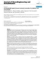
Adaptation of the neural controller to external forcesFigure 20
Adaptation of the neural controller to external
forces. The upper figure shows the effect of a force,
directed along the x-axis, applied on the end-point of the bio-
mechanical arm model and proportional to its velocity. The
shift from the arrival point induced by the disturbances is
clearly visible. The lower figure shows the behaviour of the
overall system after a training period of the neural controller
within he modified working space. The controller learns how
to take into account the effects of the external forces acting
on the dynamics of the arm model.
Publish with BioMed Central and every
scientist can read your work free of charge
"BioMed Central will be the most significant development for
disseminating the results of biomedical research in our lifetime."
Sir Paul Nurse, Cancer Research UK
Your research papers will be:
available free of charge to the entire biomedical community
peer reviewed and published immediately upon acceptance
cited in PubMed and archived on PubMed Central
yours — you keep the copyright
Submit your manuscript here:
/>BioMedcentral
Journal of NeuroEngineering and Rehabilitation 2007, 4:33 />Page 17 of 17
(page number not for citation purposes)
11. Hollerbach MJ, Flash T: Dynamic interactions between limb seg-
ments during planar arm movement. Biological cybernetics 1982,
44(1):67-77.
12. Lackner JR, Dizio P: Rapid adaptation to Coriolis force pertur-
bations of arm trajectory. Journal of neurophysiology 1994,
72(1):299-313.
13. Goodale MA, Pelisson D, Prablanc C: Large adjustments in visu-
ally guided reaching do not depend on vision of the hand or
perception of target displacement. Nature 1986,
320(6064):748-750.
14. Morasso P: Spatial control of arm movements. Experimental
brain research Experimentelle Hirnforschung 1981, 42(2):223-227.
15. Abend W, Bizzi E, Morasso P: Human arm trajectory formation.
Brain 1982, 105(Pt 2):331-348.
16. Harris CM, Wolpert DM: Signal-dependent noise determines
motor planning. Nature 1998, 394(6695):780-784.
17. Flash T, Hogan N: The coordination of arm movements: an
experimentally confirmed mathematical model. J Neurosci
1985, 5(7):1688-1703.
18. Uno Y, Kawato M, Suzuki R: Formation and control of optimal
trajectory in human multijoint arm movement. Minimum
torque-change model. Biological cybernetics 1989, 61(2):89-101.
19. Kawato M, Furukawa K, Suzuki R: A hierarchical neural-network
model for control and learning of voluntary movement. Bio-
logical cybernetics 1987, 57(3):169-185.
20. Accornero N, Capozza M: Controllo Motorio: Rete neurale
autoapprendente. Riv Neurobiol 1996, 42:206-207.
21. Hannaford B, Stark L: Roles of the elements of the triphasic
control signal. Experimental neurology 1985, 90(3):619-634.
22. Drillis R, Contini R, Bluestein M: Body Segment Parameters; a
Survey of Measurement Techniques. Artificial limbs 1964,
25:44-66.
23. Hill AV: The heat of shortening and the dynamic constants of
muscle. Proceedings of the Royal Society of London 1938, 126:136-195.
24. Caselli P, Conforto S, Schmid M, Accornero N, D'Alessio T: Differ-
ence in sensorimotor adaptation to horizontal and vertical
mirror distortions during ballistic arm movements. Human
movement science 2006, 25(3):310-325.
25. Wolpert DM, Ghahramani Z, Jordan MI: Perceptual distortion
contributes to the curvature of human reaching movements.
Exp Brain Res 1994, 98(1):153-156.
26. Atkeson CG, Hollerbach JM: Kinematic features of unrestrained
vertical arm movements. J Neurosci 1985, 5(9):2318-2330.
27. Boessenkool JJ, Nijhof EJ, Erkelens CJ: A comparison of curva-
tures of left and right hand movements in a simple pointing
task. Experimental brain research Experimentelle Hirnforschung 1998,
120(3):369-376.
28. Messier J, Kalaska JF: Comparison of variability of initial kine-
matics and endpoints of reaching movements. Experimental
brain research Experimentelle Hirnforschung 1999, 125(2):139-152.
29. Messier J, Kalaska JF: Differential effect of task conditions on
errors of direction and extent of reaching movements. Exper-
imental brain research Experimentelle Hirnforschung 1997,
115(3):469-478.