Sustainable Energy Harvesting Technologies Past Present and Future Part 4 docx
Bạn đang xem bản rút gọn của tài liệu. Xem và tải ngay bản đầy đủ của tài liệu tại đây (578.75 KB, 20 trang )
Vibration Energy Harvesting:
Machinery Vibration, Human Movement and Flow Induced Vibration
49
The electrical tuning method realizes resonant frequency tuning by adjusting electrical
loads. This method consumes little energy as it does not involve any change in mechanical
properties. In addition, it is much easier to implement than mechanical methods. However,
this method normally has a small tuning range.
The suitability of different tuning approaches depends on the application but in general
terms, the key factors for evaluating a tuning mechanism are:
• energy consumed by the tuning mechanism should be as small as possible and must not
exceed the energy produced by the energy harvester;
• the mechanism should achieve a sufficient operational frequency range;
• the tuning mechanism should achieve a suitable degree of frequency resolution;
• the strategy applied should not increase the damping over the entire operational
frequency range.
Energy harvesting from human movement is another important area in vibration energy
harvesting. As human movement is random, linear energy harvesters are not suitable for
this application. Broadband, non-linear or non-resonant devices are preferred. At the
moment, the most common locations on human body for the energy harvesters are feet and
upper body due to large displacement or force produced during movement. Up to date,
some reported energy harvesters successfully produced useful amount of electrical energy
for portable electronic devices. However, consideration needs to be taken to improve design
of the energy harvesters so that they will not cause discomfort for human body.
Furthermore, another potential solution to energy harvesting from human movement is to
print active materials on fabrics, such as jackets and trousers, so that electrical energy can be
generated while human body is moving.
Energy harvesters from flow-induced vibration, as an alternative to turbine generators, have
drawn more and more attention. Useful amount of energy has been generated by existing
devices and the start flow speed has been reduced to as low as 2.5m·s
-1
. However, most
reported devices that produce useful energy are too large in volume compared to other
vibration energy harvesters. Thus, it is difficult to integrate these devices into wireless
sensor nodes or other wireless electronic systems. Future work should focus on miniaturise
these energy harvesters while maintain current power level. In addition, researches should
be done to further reduce the start flow speed to allow this technology wider applications.
6. References
Allen, J. J. & Smits, A. J. (2001). Energy harvesting eel, In: Journal of Fluids and Structures,
Vol.15, pp. 629-640, ISSN 0889-9746
Anton, S. R. & Sodano, H. A. (2007). A review of power harvesting using piezoelectric
materials (2003-2006), In: Smart Materials and Structures, Vol.16, pp.1-21, ISSN 0964-
1726
Arakawa, Y.; Suzuki, Y. & Kasagi, N. (2004). Micro seismic power generator using electret
polymer film, Proceedings of PowerMEMS 2004, 187-190, Kyoto, Japan, November
28-30, 2004
Ayala-Garcia, I. N.; Zhu, D.; Tudor, M. J. & Beeby, S. P. (2009). Autonomous tunable energy
harvester, Proceedings PowerMEMS 2009, pp. 49-52, Washington DC, USA,
December 1-4, 2009
Sustainable Energy Harvesting Technologies – Past, Present and Future
50
Barrero-Gil, A.; Alonso, G. & Sanz-Andres, A. (2010). Energy harvesting from transverse
galloping, In: Journal of Sound and Vibration, Vol.329, pp. 2873-2883, ISSN 0022-460X
Beeby, S. P.; Tudor, M. J.; White, N. M. (2006) Energy harvesting vibration sources for
microsystems applications, In: Measurement Science and Technology, Vol.17, pp. 175-
195, ISSN 0957-0233
Beeby, S.; Tudor, M.; Torah, R.; Roberts, S.; O'Donnell, T. & Roy, S. (2007). Experimental
comparison of macro and micro scale electromagnetic vibration powered
generators, In: Microsystem Technologies, Vol.13, No.12-13, pp. 1647-1653, ISSN:
0946-7076
Beeby, S. P.; Torah, R. N.; Tudor, M. J.; Glynne-Jones, P.; O’Donnell, T.; Saha, C. R. & Roy, S.
(2007). A micro electromagnetic generator for vibration energy harvesting, In:
Journal of Micromechanics and Microengineering, Vol.17, pp. 1257-1265, ISSN 0960-
1317
Bernitsas, M. M.; Raghavan, K.; Ben-Simon, Y. & Garcia, E. M. H. (2006). VIVACE (Vortex
Induced Vibration for Aquatic Clean Energy): A new concept in generation of clean
and renewable energy from fluid flow, Proceedings of OMAE2006 25th International
OMAE Conference, Hamburg, Germany, 4-9 June, 2006
Blevins, R. D. (2001). Formulas for Natural Frequency and Mode Shape, Krieger, ISBN 1-57524-
184-6, Malabar, Forida, USA
Burrow, S. G. & Clare, L. R. (2007). A Resonant Generator with Non-Linear Compliance for
Energy Harvesting in High Vibrational Environments, IEEE International Electric
Machines and Drives Conference, pp. 715-720, Antalya, Turkey, May 3-5, 2007
Burrow, S. G.; Clare, L. R.; Carrella, A. & Barton, D. (2008). Vibration energy harvesters with
non-linear compliance, In: Active and Passive Smart Structures and Integrated Systems
2008, Proceedings of the SPIE, Vol.6928, 692807
Cammarano A.; Burrow S. G.; Barton D. A. W.; Carrella A. & Clare L. R. (2010). Tuning a
resonant energy harvester using a generalized electrical load, In: In: Smart Materials
and Structures, Vol.19, 055003(7pp), ISSN 0964-1726
Carroll, D. & Duffy, M. (2005). Demonstration of wearable power generator, Proceedings of
the 11
th
European Conference on Power Electronics and Applications, ISBN: 90-75815-09-
3, ISBN: 90-75815-09-3, Dresden, Germany, September 11-14, 2005
Charnegie, D. (2007). Frequency tuning concepts for piezoelectric cantilever beams and
plates for energy harvesting, MSc Dissertation, School of Engineering, University of
Pittsburgh, USA
Ching, N. N. H.; Wong, H. Y.; Li, W. J.; Leong, P. H. W. & Wen, Z. (2002). A laser-
micromachined vibrational to electrical power transducer for wireless sensing
systems, In: Sensors and Actuators A: Physical, Vol.97-98, pp. 685-90, ISSN 0924-4247
Despesse, G.; Jager, T.; Chaillout, J.; Leger, J.; Vassilev, A.; Basrour, S. & Chalot, B. (2005).
Fabrication and characterisation of high damping electrostatic micro devices for
vibration energy scavenging, Proceedings of Design, Test, Integration and Packaging of
MEMS and MOEMS, pp. 386–390, Montreux, Switzerland, June 1-3, 2005
Dunnmon, J. A.; Stanton, S. C.; Mann, B. P. & Dowell, E. H. (2011). Power extraction from
aeroelastic limit cycle oscillations, In: Journal of Fluids and Structures,
doi:10.1016/j.jfluidstructs.2011.02.003, ISSN 0889-9746
Eichhorn, C.; Tchagsim, R.; Wilhelm, N.; Goldschmidtboeing, F. & Woias, P. (2010). A
compact piezoelectric energy harvester with a large resonance frequency tuning
range, Proceedings PowerMEMS 2010, pp. 207-211, Leuven, Belgium, December 1-3,
2010
Vibration Energy Harvesting:
Machinery Vibration, Human Movement and Flow Induced Vibration
51
Elfrink, R.; Kamel, T. M.; Goedbloed, M.; Matova, S.; Hohlfeld, D.; van Andel,Y. & van
Schaijk, R. (2009). Vibration energy harvesting with aluminum nitride-based
piezoelectric devices, In: Journal of Micromechanics and Microengineering, Vol.19,
No.9, 094005, ISSN 0960-1317
Erturk, A.; Hoffmann, J. & Inman, D. J. (2009). A piezomagnetoelastic structure for
broadband vibration energy harvesting, In: Applied Physics Letters, Vol.94, 254102,
ISSN 0003-6951
Erturk, A.; Vieira, W. G. R.; De Marqui, C. Jr. & Inman, D. J. (2010). On the energy harvesting
potential of piezoaeroelastic systems, In: Journal of Applied Physics, Vol.96, 184103,
ISSN 0021-8979
Fang, H. B.; Liu, J. Q.; Xu, Z. Y.; Dong, L.; Wang, L.; Chen, D.; Cai, B. C. & Liu, Y. (2006).
Fabrication and performance of MEMS-based piezoelectric power generator for
vibration energy harvesting, In: Microelectronics Journal, Vol.37, No.11, pp. 1280-
1284, ISSN 0026-2692
Feenstra, J.; Granstrom, J.; and Sodano, H. A. (2008). Energy harvesting through a backpack
employing a mechanically amplified piezoelectric stack, In: Mechanical Systems and
Signal Processing, Vol.22, pp. 721–734, ISSN 0888-3270
Ferrari, M.; Ferrari, V.; Guizzetti, M.; Marioli, D. & Taroni, A. (2008). Piezoelectric
multifrequency energy converter for power harvesting in autonomous
Microsystems, In: Sensors Actuators A: Physical, Vol.142, pp. 329–335, ISSN 0924-
4247
Ferrari, M.; Ferrari, V.; Guizzetti, M.; Andò, B.; Baglio, S. and Trigona, C. (2009). Improved
Energy Harvesting from Wideband Vibrations by Nonlinear Piezoelectric
Converters, Proceedings of Eurosensors XXIII, Lausanne, Switzerland, September 6-9,
2009
Gieras, J. F.; Oh, J H.; Huzmezan, M. & Sane, H. S. (2007). Electromechanical energy harvesting
system, Patent Publication Number: WO2007070022(A2), WO2007070022(A3)
Glynne-Jones, P.; Tudor, M. J.; Beeby, S. P. & White, N. M. (2004). An electromagnetic,
vibration-powered generator for intelligent sensor systems, In: Sensors and
Actuators A: Physical, Vol.110, pp. 344-349, ISSN 0924-4247
Goldschmidtboeing, F. & Woias, P. (2008). Characterization of different beam shapes for
piezoelectric energy harvesting, In: Journal of Micromachining and Microengineering,
Vol.18, 104013, ISSN 0960-1317
Granstrom, J.; Feenstra, J.; Sodano, H. A. & Farinholt, K. (2007). Energy harvesting from a
backpack instrumented with piezoelectric shoulder straps, In: Smart Materials and
Structures, Vol.16, pp. 1810-1820, ISSN 0964-1726
Hoffmann, D.; Folkmer, B. & Yiannos, M. (2009). Fabrication, characterization and
modelling of electrostatic micro-generators, In: Journal of Micromechanics and
Microengineering, Vol.19, No.9, 094001, ISSN: 0960-1317
Huesgen, T.; Woias, P. & Kockmann, N. (2008). Design and fabrication of MEMS
thermoelectric generators with high temperature efficiency, In: Sensors and
Actuators A: Physical, Vol.145-146, pp. 423-429, ISSN 0924-4247
Humdinger Wind Energy, LLC, (accessable on 13 May
2011).
Jungm, H J. & Lee, S W. (2011). The experimental validation of a new energy harvesting
system based on the wake galloping phenomenon, In: Smart Materials and
Structures, Vol.20, 055022 (10pp), ISSN 0964-1726
Sustainable Energy Harvesting Technologies – Past, Present and Future
52
Kim, S H.; Ji, C H.; Galle, P.; Herrault, F.; Wu, X.; Lee, J H.; Choi, C A. & Allen, M. G.
(2009). An electromagnetic energy scavenger from direct airflow, In: Journal of
Micromechanics and Microengineering, Vol.19, 094010 (8pp), ISSN 0960-1317
Kok, S L.; White, N. M. & Harris, N.R. (2009). Fabrication and characterization of free-
standing thick-film piezoelectric cantilevers for energy harvesting, In:
Measurement Science and Technology, Vol.20, 124010, ISSN 0957-0233
Koukarenko, E.; Beeby, S. P.; Tudor, M. J.; White, N. M.; O’Donnell, T.; Saha, T.; Kulkani, S.
& Roy, S. (2006). Microelectromechanical systems vibration powered
electromagnetic generator for wireless sensor applications, In: Microsystem
Technologies, Vol.12, No.11, pp 1071-1077, ISSN 0946-7076
Kymissis, J.; Kendall, C.; Paradiso, J. & Gershenfeld, N. (1998). Parasitic power harvesting in
shoe, Digest of Papers. Second International Symposium on Wearable Computers,
PP. 132-139, ISBN 0-8186-9074-7, Pittsburgh, Pennsylvania, USA, October 19-20,
1998
Leland, E. S. & Wright, P. K. (2006). Resonance tuning of piezoelectric vibration energy
scavenging generators using compressive axial, In: Smart Materials and Structures,
Vol.15, pp.1413-1420, ISSN 0964-1726
Li, S. & Lipson, H. (2009). Vertical-stalk flapping-leaf generator for wind energy harvesting,
Proceedings of the ASME 2009 Conference on Smart Materials, Adaptive Structures and
Intelligent Systems, Oxnard, California, USA, September 21-23, 2009
Li, S.; Yuan, J. & Lipson, H. (2011). Ambient wind energy harvesting using cross-flow
fluttering, In: Journal of Applied Physics, Vol.109, 026104, ISSN 0021-8979
Liao, Y. & Sodano, H. A. (2008). Model of a Single Mode Energy Harvester and Properties
for Optimal Power Generation, In: Smart Materials and Structures, Vol.17, 065026,
ISSN 0964-1726
Liu, F.; Phipps, A.; Horowitz, S.; Ngo, K.; Cattafesta, L.; Nishida, T. & Sheplak, M. (2008).
Acoustic energy harvesting using an electromechanical Helmholtz resonator, In:
Journal of Acoustical Society of America, Vol.123, Vo.4, pp 1983-1990, ISSN: 0001-4966
Lo, H. & Tai, Y. C. (2008). Parylene-based electret power generators, In: Journal of
Micromachining and Microengineering, Vol.18, 104006, ISSN: 0960-1317
Marzencki, M.; Ammar, Y; & Basrour, S. (2008). Integrated power harvesting system
including a MEMS generator and a power management circuit, In: Sensors and
Actuators A: Physical, Vol.145-146, pp. 363-370, ISSN 0924-4247
Matova, S. P.; Elfrink, R.; Vullers, R. J. M. & van Schaijk, R. (2010). Harvesting energy from
airflow with micromachined piezoelectric harvester inside a Helmholtz resonator,
Proceedings of PowerMEMS 2010, Leuven, Belgium, November 30 - December 3,
2010
MicroBelt tech sheet,
(accessable on 13 May 2011)
Mitcheson, P.; Stark, B.; Miao, P.; Yeatman, E.; Holmes, A. & Green, T. (2003). Analysis and
optimisation of MEMS on-chip power supply for self powering of slow moving
sensors, Proceedings of Eurosensors XVII Conference, pp. 48-51, Guimaraes, Portugal,
September 21-24, 2003
Nguyen, D. S. & Halvorsen, E. (2010). Analysis of vibration energy harvesters utilizing a
variety of nonlinear springs, Proceedings of PowerMEMS 2010, Leuven, Belgium,
November 30 - December 3, 2010
Norman, B. C. (2007). Power options for wireless sensor networks, In: IEEE Aerospace and
Electronic Systems Magazine, Vol.22, No.4, pp. 14-17, ISSN 0885-8985
Vibration Energy Harvesting:
Machinery Vibration, Human Movement and Flow Induced Vibration
53
Peters, C.; Maurath, D.; Schock, W. & Manoli, Y. (2008). Novel electrically tunable
mechanical resonator for energy harvesting, Proceedings PowerMEMS 2008+
μ
EMS2008, pp. 253-256, Sendai, Japan, November 9-12, 2008
Ramlan, R. (2009). Effects of non-linear stiffness on performance of an energy harvesting
device, PhD Thesis, University of Southampton, UK
Renaud, M.; Karakaya, K.; Sterken T.; Fiorini P.; Vanhoof, C. & Puers R. (2008). Fabrication,
Fabrication, modelling and characterization of MEMS piezoelectric vibration
harvesters, In: Sensors and Actuators A: Physical, Vol.145-146, No.1, pp. 380-386,
ISSN: 09244247
Peters, C.; Maurath, D.; Schock, W.; Mezger, F. & Manoli, Y. (2008). A closed-loop wide-
range tunable mechanical resonator for energy harvesting systems, In: Journal of
Micromechanics and Microengineering, Vol.19, No.9, 094004(9pp), ISSN 0960-1317
Rome, L. C.; Flynn, L. & Yoo, T. D. (2005) Generating electricity while walking with loads,
Science, Vol.309, No.5741, (September 2005), pp. 1725-1728, ISSN 0036-8075
Romero, E.; Warrington, R. O. & Neuman, M. R. (2009). Energy scavenging sources for
biomedical sensors, In: Physiological Measurement, Vol.30, pp. 35-62, ISSN 0967-3334
Roundy, S.; Wright, P. K. & Rabaey, J. (2003). A study of low level vibrations as a power
source for wireless sensor nodes, In: Computer Communications, Vol.26, pp. 1131-
1144, ISSN 0140-3664
Roundy, S. & Wright, P. K. (2004). A piezoelectric vibration based generator for wireless
electronics, In: Smart Materials and Structures, Vol.13, pp. 1131-1142, ISSN 0964-1726
Roylance, L. & Angell, J. B. (1979). A batch fabricated silicon accelerometer, In: IEEE Trans.
Electron Devices, Vol.26, pp. 1911–1917, ISSN 0018-9383
Saha, C. R.; O’Donnell, T.; Loder, H.; Beeby, S. P. & Tudor, M. J. (2006). Optimization of an
electromagnetic energy harvesting device, In: IEEE Transactions on Magnetics,
Vol.42, No.10, pp. 3509-3511, ISSN 0018-9464
Saha, C. R.; O’Donnell, T.; Wang, N. & McCloskey P. (2008). Electromagnetic generator for
harvesting energy from human motion, In: Sensors and Actuators A: Physical,
Vol.147, pp. 248–253, ISSN 0924-4247
Sanchez-Sanz, M.; Fernandez, B. & Velazquez, A. (2009). Energy-harvesting microresonator
based on the forces generated by the Karman street around a rectangular prism, In:
Journal of Microelectromechanical Systems, Vol.18, No.2, pp. 449-457, ISSN 1057-7157
Sari, I.; Balkan, T. & Kulah, H. (2007). A wideband electromagnetic micro power generator
for wireless Microsystems, Proceedings of International Solid-State Sensors, Actuators
and Microsystems Conference 2007, pp 275-278, Lyon, France, June 10-14, 2007
Shen, D.; Park, J.; Ajitsaria, J.; Choe, S.; Wikle, H. C. & Kim, D. (2008). The design, fabrication
and evaluation of a MEMS PZT cantilever with an integrated Si proof mass for
vibration energy harvesting, In: Journal of Micromechanics and Microengineering,
Vol.18, No.5, 55017, ISSN 0960-1317
Spreemann, D.; Folkmer, B.; Maurath, D. & Manoli, Y. (2006). Tunable transducer for low
frequency vibrational energy scavenging, Proceedings of EurosensorsXX, Göteborg,
Sweden, September 17-20, 2006
St. Clair, D.; Bibo, A.; Sennakesavababu, V. R.; Daqaq, M. F. & Li, G. (2010). A scalable
concept for micropower generation using flow-induced self-excited oscillations, In:
Journal of Applied Physics, Vol.96, 144103, ISSN 0021-8979
Taylor, G. W.; Burns, J. R.; Kammann, S. M.; Powers, W. B. & Welsh, T. R. (2001). The energy
harvesting eel: a small subsurface ocean/river power generator, In: IEEE Journal of
Oceanic Engineering, Vol.26, No.4, pp. 539-547, ISSN 0364-9059
Sustainable Energy Harvesting Technologies – Past, Present and Future
54
Torah, R. N.; Glynne-Jones, P.; Tudor, M. J.; ODonnell, T.; Roy S. & Beeby S. P. (2008). Self-
powered autonomous wireless sensor node using vibration energy harvesting, In:
Measurement Science and Technology, Vol.19, 125202, ISSN 0957-0233
Mann, B. P. & Owens, B. A. (2010). Investigations of a nonlinear energy harvester with a
bistable potential well, In: Journal of Sound and Vibration, Vol.329, pp. 1215–1226,
ISSN 0022-460X
von Buren, T. (2006) Body-Worn Inertial Electromagnetic Micro-Generators, PhD Thesis,
Swiss Federal Institute of Technology Zurich, Zurich, Switzerland
Wang, D A. & Chang, K H. (2010). Electromagnetic energy harvesting from flow induced
vibration, In: Microelectronics Journal, Vol.41, pp. 356–364, ISSN 0026-2692
Wang, D A. & Ko, D A. (2010). Piezoelectric energy harvesting from flow-induced
vibration, In: Journal of Micromechanics and Microengineering, Vol.20, 025019 (9pp),
ISSN 0960-1317
Wang, D A. & Liu, N Z. (2011). A shear mode piezoelectric energy harvester based on a
pressurized water flow, In: Sensors and Actuators A: Physics, Vol.167, No.2, pp. 449-
458, ISSN 0924-4247
Wang, D A.; Pham, H T.; Chao, C W. & Chen, J. M. (2011). A piezoelectric energy
harvester based on pressure fluctuations in Kármán Vortex Street, Proceedings
World Renewable Energy Congress 2011, Linköping, Sweden, 8-11 May 2011
Wang, P.; Dai X.; Zhao X. & Ding G. (2009). A micro electromagnetic vibration energy
harvester with sandwiched structure and air channel for high energy conversion
efficiency, Proceedings PowerMEMS 2009, pp. 296-299, Washington DC, USA,
December 1-4, 2009
Williams, C. B. & Yates, R. B. (1996) Analysis of a micro-electric generator for microsystems,
In: Sensors and Actuators A, Vol.52, pp. 8-11, ISSN 0924-4247
Williams, C. B.; Shearwood, C.; Harradine, M. A.; Mellor, P. H.; Birch, T. S. & Yates, R. B.
(2001). Development of an electromagnetic micro-generator, In: IEE Proceedings of
Circuits Devices Systems, Vol.148, pp. 337-342, ISSN 1350 -2409
Wu, X.; Lin, J.; Kato, S.; Zhang, K.; Ren, T. & Liu, L. (2008). A frequency adjustable vibration
energy harvester, Proceedings of PowerMEMS 2008+
μ
EMS2008, pp. 245-248, Sendai,
Japan, November 9-12, 2008
Zhu, D.; Tudor, M. J. & Beeby, S. P. (2010). Strategies for increasing the operating frequency
range of vibration energy harvesters: a review, In: Measurement Science and
Technology, Vol.21, 022001(29pp), ISSN 0957-0233
Zhu, D.; Roberts, S.; Tudor, J. & Beeby, S. (2010). Design and experimental characterization
of a tunable vibration-based electromagnetic micro-generator, In: Sensors and
Actuators A: Physical, Vol.158, No.2, pp. 284-293, ISSN 0924-4247
Zhu, D.; Beeby, S.; Tudor, J.; White, N. & Harris, N. (2010). A novel miniature wind
generator for wireless sensing applications, Proceedings IEEE Sensors 2010, ISBN
978-1-4244-8170-5, Waikoloa, Hawaii, USA, November 1-4, 2010
Zhu, D.; Almusallam, A.; Beeby, S.; Tudor, J. & Harris, N. (2010). A Bimorph Multi-layer
Piezoelectric Vibration Energy Harvester, Proceedings of PowerMEMS 2010, Leuven,
Belgium, December 1-3, 2010
Zhu, D. & Beeby, S. (2011). Kinetic energy harvesting, In: Energy Harvesting Systems:
Principles, Modeling and Applications, pp. 1-78, Springer, ISBN 978-1-4419-7565-2,
New York Dordrecht Heidelberg London
Zhu, D.; Beeby S.; Tudor J. and Harris N. (2011) A credit card sized self powered smart
sensor node, In: Sensors and Actuators A: Physical, Vol.169, No.2 pp. 317-325, ISSN
0924-4247
3
Modelling Theory and Applications of the
Electromagnetic Vibrational Generator
Chitta Ranjan Saha
Score Project, School of Electrical & Electronic Engineering University of Nottingham,
Nottingham, NG7 2RD
UK
1. Introduction
There is rapidly growing interest over the last decade on the topics of energy harvesting
devices as a means to provide an alternative to batteries as a power source for medical
implants, embedded sensor applications such as buildings or in difficult to access or remote
places where wired power supplies would be difficult [1-13]. There are several possible
sources of ambient energy including vibrational, solar, thermal gradients, acoustic, RF, etc that
can be used to power the sensor modules or portable electronic devices. The most promising
ambient energy sources of these are solar, thermo-electric and vibrational. A significant
amount of research has already been done in this area over the past few years and several
energy scavenger products are already available in the market such as the solar calculator,
thermoelectric wristwatch and wireless push button switches etc. The Solar energy is a mature
technology and represents a very straight forward approach to generate energy from ambient
light. However, solar cell is not cost effective and devices using solar cell need larger areas
which would not be compatible with small MEMS powering. Furthermore sufficient sunlight
is necessary which also limits the application areas. In thermoelectric generators, large thermal
gradients are essential to generate practical levels of voltage and power. It would be very
difficult to get more than 10°C in a MEMS compatible device. On the other hand, vibrational
energy scavenger could be a reliable option for autonomous sensor modules or body-worn
sensor, in automotive, industrial machine monitoring or other applications where ambient
vibrational energy is available. This vibrational energy can be converted into electrical energy
using three different principles: electromagnetic, electrostatic and piezoelectric.
The modelling theory of the electromagnetic (EM) vibrational generator (energy scavenger)
and its applications are main objective in this chapter in order to understand the limitations
of the EM energy harvesting device and how to increase voltage and power level for a
specific application. Initially, this chapter gives the basic working principles of vibrational
energy harvester and electrical machines. Then it will provide the modelling and
optimization theory of the linear EM vibrational energy scavenger and discuss the analytical
equations of each modelling parameter. Thereafter, this chapter presents the few macro
scale cantilever prototypes which have been built and tested. Their measured results are
discussed and analysed with the theory in order to see the accuracy of the model. It will also
investigate the possible applications of the vibrational energy harvester. A prototype of the
Sustainable Energy Harvesting Technologies – Past, Present and Future
56
magnetic spring generator which has been built and tested for human body motion is
presented and discussed the advantages of this structure. Finally we will present a prototype
of optimized cantilever micro generator which has been built and integrated with the
autonomous sensor module for machine monitoring application. The measured results of the
real prototypes will provide the depth understanding of the readers what level of voltage and
power could be harvested from the macro and micro level EM energy harvester and whether
micro or macro device would be suitable for particular applications. The next section will give
the brief overview of the working principle of the vibrational energy harvesters.
1.1 Kinetic/vibrational energy harvesting
Kinetic energy is the energy associated with the motion of an object. This includes
vibrational motion, rotational motion and translational motion. The kinetic energy depends
on two variables, the mass of the moving object (m) and the speed (U) of the object and is
defined by [14];
2
1
.
2
KE mU=
(1)
Kinetic energy is a scalar quantity and it is directly proportional to the square of its speed. In
kinetic energy-harvesting, energy can be extracted from ambient mechanical vibrations
using either the movement of a mass object or the deformation of the harvesting device. The
basic operating principle of ac generator or alternator
or EM harvester can be expressed
using the energy flow diagram shown in Figure 1. When this external mechanical vibration
or force is sufficient enough to overcome the mechanical damping force then the mass
component of the energy harvesting devices to move or oscillate. This mechanical energy
can be converted into electrical energy by means of an electric field (electrostatic), magnetic
field (electromagnetic) or strain on a piezoelectric material, which are commonly known as
electromechanical energy conversion principles. There also exists magnetostrictive energy
harvesting devices which combine two principles: electromagnetic and piezoelectric.
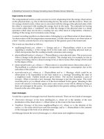
Fig. 1. Energy flow diagram of mechanical to electrical energy conversion principle.
Input mechanical
energy
Mechanical coupling
Generated mechanical
energy
Efficiency of
Energy conversion
Available electrical energy
Load energy
Mechanical loss in
coupling
Electrical loss
Modelling Theory and Applications of the Electromagnetic Vibrational Generator
57
Depending on the nature of the mechanical force, the generator can be classified in three
categories: rotational generators, linear generators and deformation structure generators.
The micro and macro scale linear or EM rotational generator, which is commonly known as
an inertia generator in energy harvesting areas, will be investigated. Before introducing the
EM energy harvester it is necessary to give a brief overview of the electrical machines such
as transformer, motor and generator. Also the study of magnetic circuits is important since
the operation of the EM energy harvester could be easily analyzed using the behavior of the
magnetic fields. The next section will present the basic concepts of the electrical machines in
order to understand the operating principle of the electromagnetic machines.
1.2 Concepts of electrical machine
An electrical machine is a electromechanical device that can convert either electrical energy
to mechanical energy (known as a motor) or mechanical energy to electrical energy (known
as generator). When such a device generates power in both directions it can be used as either
a generator or a motor. The process of the electromechanical energy conversion normally
involves the interaction of electric circuits and magnetic fields and the associated mechanical
movement. This movement could be either rotational or linear due to forces arising between
the fixed and the moving parts of the machine when we describe them as a rotational or
linear machine. Another closely- related device is the transformer, which converts ac
electrical energy at one voltage level to ac electrical energy at another voltage level. These
three types of devices are very important in our everyday lives and sometimes such energy
conversion devices are called transducer. One of the common factors between these
machines is that they make use of magnetic fields to convert one form of energy to another.
How these magnetic fields are used in such devices can be described by four basic principles
[15-17];
1. A magnetic field will be produced surrounding a current-carrying conductor.
2. A time-changing magnetic field induces a voltage in a coil when it passes through it,
which is called transformer action.
3. A current carrying conductor experiences a force in the presence of a magnetic field;
this is known as motor action.
4. When a conductor such as copper wire moves in the magnetic field, a voltage will be
induced between the conductor terminals; this is known as generator action.
The fourth principle is commonly known as Faraday’s electromagnetic induction principle
which has a wide range of applications, especially in power generation and power
transmission theory. The following section will highlight the key components of the
magnetic circuits since the magnetic field analysis is required to predict the performance of
the electromagnetic device.
1.3 Magnetic materials and permanent magnet circuit model
Magnets are made from the magnetic materials and magnetic substances which consist of
different metallic alloys. The magnetic materials are classified according to the nature of its
relative permeability (µ
r
) which is actually related to the internal atomic structure of the
material and how much magnetization occurs within material. There are three categories the
magnetic materials can be classified such as ferromagnetic materials, paramagnetic
Sustainable Energy Harvesting Technologies – Past, Present and Future
58
materials and diamagnetic materials. It is necessary to know the few quantities of the
magnetic material such as magnetic flux density, B ( T = wb/m
2
), the magnetizing force, H
(A/m) and the magnetic flux,
φ
(wb). The relation between the magnetic flux density and
the magnetizing force can be defined by;
HHB
r 0
μ
μ
μ
=
=
(2)
Where
μ
(H/m) is the material permeability,
r
μ
is the relative permeability and
0
μ
is the
permeability in free space 4
π
x 10
-7
H/m.
1.3.1 Ferromagnetic materials
The ferromagnetic materials have very large positive values of magnetic permeability and
they exhibit a strong attraction to magnetic fields and are able to retain their magnetic
properties after the external field has been removed. The relative permeability of
ferromagnetic material could be a few hundred to a few thousand and they are highly
nonlinear. Ferromagnetic materials those are easily magnetized called soft magnetic
materials such as soft iron, silicon steel, soft ferrites, nickel-iron alloys etc. Soft magnetic
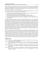
materials have a steeply rising magnetization curve, relatively small and narrow hysteresis
loop as shown in figure 2 (a). They are normally used in inductors, motors, actuators,
transformer, sonar equipments and radars. Those ferromagnetic materials have a gradually
rising magnetization curve, large hysteresis loop area and large energy loss for each cycle of
magnetization as shown in figure 2 (b) called hard magnet or permanent magnet. Alnico,
Ceramic, Rare-earth, Iron-chromium-Cobalt, Neodymium-Iron-boron etc are few examples
of permanent magnet materials. The more details of the Hysteresis loop (B-H curve) is
explained in different literatures [16-17].
1.3.2 Paramagnetic materials
The paramagnetic materials have small, positive values of magnetic permeability to
magnetic fields. These materials are weakly attracted by the magnets when placed in a
magnetic field and the materials could not retain the magnetic properties when the external
field is removed. Potassium, aluminum, palladium, molybdenum, lithium, copper sulphate
etc are common paramagnetic materials.
1.3.3 Diamagnetic materials
The diamagnetic materials have a weak, negative magnetic permeability to magnetic fields.
Diamagnetic materials are slightly repelled by the magnets when placed in a magnetic field
and the material does not retain the magnetic properties when the external field is removed.
The examples of diamagnetic materials are bismuth, copper, diamond, gold etc.
Since the permanent magnet will be used to build the prototype of the electromagnetic
vibrational power generator and it is necessary to understand the air gap flux density
between magnet and coil. The magnetic excitation is supplied by permanent magnets which
are used in all electromagnetic energy conversion devices and the air gap magnetic field
density provides valuable information in evaluating the performance of any permanent
Modelling Theory and Applications of the Electromagnetic Vibrational Generator
59
magnet machine. Most designers use simplified analytical models of magnetic fields in the
early stage design and then use FEA in the second stage of the design for better performance
evaluation. For this work, rectangular- shaped magnets are assumed. A method for
calculating the field at any point due to a rectangular magnet has been presented in [18].
Each magnet has eight corners and each corner flux density is equal to the remanent (B
r
) of
the magnet.
(a) (b)
Fig. 2. Hysteresis loop (a) Soft magnetic materials (b) Hard magnetic materials.
Since the magnet has two opposite polarities, the remanent would be positive and negative
consecutively as shown in figure 3. Suppose one corner co-ordinate is (x
k
,y
k
,z
k
) with
remanent (-B
r
) and the flux density at a point M(x,y,z) outside the magnet can be calculated
[18] from the following equation,
)arctan(
222
rrrr
rr
rzk
zyxz
yx
BB
++
−=
(3)
Where B
zk
is the flux density in the magnetization direction and
kr
xxx −=
,
yyy
kr
−=
and
zzz
kr
−=
. The total flux density M(x,y,z) would be the summation of the eight
corner flux densities.
Now we will discuss the magnetic circuit model of the permanent magnet. The second
quadrant of the hysteresis loop is very valuable to describe the demagnetization
characteristic of the permanent magnet. Figure 4 shows the linear demagnetization curve of
the different permanent magnets [17-19]. Let consider the uniform cross sectional area and
B : Magnetic flux density (T)
H : Ampere per meter/Magnetizing force
Sustainable Energy Harvesting Technologies – Past, Present and Future
60
length of permanent magnet are A
p
and l
p
respectively as shown in figure 5. The intersection
of the loop with the horizontal axis (H) is known as the coercive force, H
c
and the vertical
axis (B) is known as the remanent flux density (Br) or residual flux density. The linear
demagnetization curve can be defined by;
)()(
cppcp
c
r
p
HHHH
H
B
B +=+=
μ
(4)
Fig. 3. Magnet flux density calculation
Where
c
r
p
H
B
=
μ
is the permanent magnet permeability. The electrical analogy of the
magnetic components for flux linkage (
φ
) as current (I), the magnetomotive force (F
p
) as a
voltage source (E) and the magnetic reluctance as the resistance. The voltage drop across the
magnet can be defined as [19];
ppppcp
pp
p
pp
FlH
A
l
lH −ℜ=−=
φφ
μ
(5)
Where
p
ℜ
is the magnetic reluctance of the permanent magnet,
p
φ
is the flux linkage and
F
p
is the magnetomotive force of the permanent magnet.
There is non linear demagnetization curve of the permanent magnet, linear magnetic circuit
is still valid however the magnetic permeability would be;
cp
p
p
HH
B
+
=
μ
(6)
The non linear magnetic circuit model of the permanent magnet can be represented in the
figure 6. It can be seen from figure 7 that if the external magnetic field (H
ex
) applied, the
magnet operating point (H
p
,B
p
) would not move along the non-linear demagnetization
curve, it simply moves along the centre line of the minor loop.
M(x,y,z)
N
S
+B
r
-
+B
r
-B
r
y
k
,z
k
)
N
S
+B
r
-
+B
r
-B
r
k
,
k
)
( x
k,
B
r
Modelling Theory and Applications of the Electromagnetic Vibrational Generator
61
Fig. 4. Demagnetization curve of the permanent magnet [19]
Fig. 5. Linear magnet circuit model of the permanent magnet.
NdFeB
SmCo
B
(
T
)
H
(
A/m
)
B
p
l
p
Ap
H
p
B
p
H
p
l
p
p
φ
pp
p
p
A
l
μ
=ℜ
pcp
lHF =
Sustainable Energy Harvesting Technologies – Past, Present and Future
62
Fig. 6. Magnetic circuit model of a magnet using non-linear demagnetization curve.
Fig. 7. Movement of the operating point of the magnet due to external magnetic field
In the next section, we will give a brief overview of Faraday’s electromagnetic induction law
and its fundamental equations.
1.4 Faraday’s electromagnetic generator
Faraday discovered the electromagnetic induction which can be seen as a flux cutting
phenomenon. If an electric conductor is moved through perpendicular to a magnetic field so
as to cut the flux lines, a potential difference is induced between the ends of the conductor
[16-17]. He also first developed the homopolar type electromagnetic generator which used a
copper disc rotating between the poles of a horseshoe magnet; this is known as a Faraday
disc. The principle of Faraday’s law is applicable to the case where the time variation of
voltage is created from the variation of the flux linkage of a stationary coil or a coil moves
through a static magnetic flux or combination of both situations. Suppose the change in flux
linkage in the circuit occurs within a small time interval Δt, then the induced emf can be
defined by:
dt
d
t
V
φ
φ
=
Δ
Δ
=
(7)
H
c
+ H
p
H
p
H
p
+ H
c
Modelling Theory and Applications of the Electromagnetic Vibrational Generator
63
where V is the generated voltage/induced emf and
φ
is the flux linkage.
If we consider the case where a coil moves in the x direction through a magnetic field or flux
density B where B field varies along the coil movement, then the voltage can be expressed
as:
dt
dx
dx
d
V
φ
=
(8)
The flux linkage depends on the magnet and coil parameters and the air gap flux density
between the magnet and coil. The shape of the air gap flux density could vary with the
magnetic structure of the generator. The situation for vibrational generators can be
approximated by a coil moving in a single direction through a magnetic field which varies
in the direction of movement, as depicted in Figure 8. The flux linkage through a single turn
conductor which encircles a surface area (dA=dxdy), and which is positioned in a B field
which varies with x but not y, can be expressed as;
∫∫∫ ∫∫
Δ
Δ===
x
dxxBydxdyBdAB
0
)(
φ
and the flux linkage gradient is therefore;
)]0()([ BxBy
dx
d
−ΔΔ=
φ
(9)
where B(0) and B(Δx) are the flux density at the x=0 position and the x=Δx position.
The expression for the generated voltage as the product of the flux linkage gradient and the
velocity is important for understanding the operation of the vibrational generator.
X
Y
Z
(0, 0, 0)
(Δx, Δy, 0)
(Δx, 0, 0)
(0, Δy, 0)
U
B
Fig. 8. Movement of a conductor in a position varying magnetic field.
Sustainable Energy Harvesting Technologies – Past, Present and Future
64
1.4.1 Loudspeaker type vibrational generator
Figure 9 shows the schematic of a typical moving coil loudspeaker type linear generator. The
loudspeaker type generator consists of a moving coil inside a static magnetic field where the
voice coil is connected to the cone and its suspension [20]. Normally the cone is made from
carbon fibre, plasticized cloth or paper. The magnet assembly consists of front plate, back
plate, yoke pole pitch which are mainly made from low cost iron material and a large ferrite
magnet. In the majority of loudspeaker designs the magnet height is longer than the coil height
and the coil movement within the magnet height for full excursion. The flux density over the
coil movement is constant for this kind of structure. The generated voltage would be;
BlUV
=
(10)
Since the loudspeaker suspension is made from plastic, fibre or papers etc which are high
loss material. Normally it is designed for small movement and will be flat response over the
frequency range. The electromagnetic vibrational generator requires a particular frequency
response with high efficiency.
Fig. 9. Typical loudspeaker structure
Cone
Voice Coil
Yoke pole piece
Front
suspension
Rear
suspension
Ferrite
magnet
Vent holes
Front
plate
Back plate
Modelling Theory and Applications of the Electromagnetic Vibrational Generator
65
Magnet
Coil
-0.8
-0.6
-0.4
-0.2
0
0.2
0.4
0.6
0.8
0123
Distance(mm)
Flux density(T)
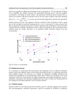
Fig. 10. Air gap flux density along the coil axis of the four magnets and single coil generator
structure.
D=Coil outer diameter
L =magnet length
H = magnet
height
G= Gap between
magnet and coil
Magnetization
angle
Sustainable Energy Harvesting Technologies – Past, Present and Future
66
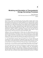
1.4.2 Four magnets vibrational generators
In this chapter rectangular shape four magnets and single coil generator structure is used for
macro and micro scale prototype to verify the modeling theory. Figure 10 shows finite
element simulation results of the air gap flux density (B) of the four magnet generator
structure along the coil axis. This four magnet generator has several advantages. Since the
coil is placed in the gap between upper and lower magnets, the field experienced by this coil
is relatively large. In addition, the field is mostly perpendicular to the coil so that it
contributes efficiently to the generated voltage. A four-magnets arrangement is used so as to
produce two pole pairs. In its resting position, the coil is positioned mid-way between these
pole pairs, i.e. half of the coil rests under one pole and half under the other. This is
important as it means that the coil is subjected to a high flux gradient which should thus
give rise to a relatively high voltage. It can be seen from this figure that the flux density is
maximum at the mid position in each magnet and the flux density is zero between the mid
points of the pole pairs.
It is fundamental to know the application before designing the generator. Need to consider
the issues what level of acceleration or force and frequency are available and whether macro
or micro size magnet and coil would generate sufficient power. Also what kind of generator
structure such as magnet, coil and suspension would be suitable for the specific application?
Finally how magnet and coil could be optimized to reduce cost and size for the specific
application to deliver maximum power.
In the following section, we discuss the details of the model and the optimum condition for
the generator.
1.5 Model of the electromagnetic vibrational generator
The basic vibrational energy harvester can be modeled as a second order mass damper and
spring system [1-6]. It consists of a mass (m) mounted on a spring or a beam (k) which
vibrates relative to a housing when subjected to an external vibrational force. For an
electromagnetic generator mass may consist of the magnet itself or the coil. Figure 11 shows
the typical structure of a generator as described by P.Glynne-Jones [21]. In this generator,
two opposite polarity magnets were fixed in a gap at the free end of the cantilever and a
wire-wound coil was placed in the gap between the magnets. When the external force is
applied to the generator housing, the voltage would be generated in the coil terminal due to
the relative displacement between magnets and coil. In order to have a model, it is
important to develop the equations for the various generator parts such as the magnet
parameters, the coil parameters, beam parameters and damping (D) parameters.
Figure 12 shows the schematic diagram of the electromagnetic generator. Variables z and y
are the displacements of the generator mass and housing, respectively. It is assumed that
movement of the housing is unaffected by the movement of the generator, since the moving
mass (m) is much smaller than the mass of the generator housing. For a sinusoidal
excitation,
)sin(
0
tYy
ω
=
, where Y
o
is the vibration amplitude and ω is the frequency of
vibration. The equation of motion for the mass relative to the housing at no load condition
(no electromagnetic forces considered) can be defined [4-5] by the following equation,
Modelling Theory and Applications of the Electromagnetic Vibrational Generator
67
Fig. 11. Typical generator structure
tFtmakx
dt
dx
D
dt
xd
m
p
ω
sin)(
0
2
2
=−=++
(11)
where m is the moving mass of the generator, x is the relative movement between the mass
and the housing, D
p
is the parasitic damping, and F
o
= mω
2
a . The parasitic damping of the
generator is commonly known as mechanical loss and can consist of air resistance loss,
surface friction loss, material hysteresis loss, etc. It depends on material properties, the size
and shape of the generator, external force, frequency, and vibrational displacement. k
is the
beam spring constant where the natural resonant frequency
ω
n
is given by,
mk
n
/=
ω
. The
steady state solution of equation (4) is the displacement for the no-load condition and is
given by the following equation [4]:
222
0
)()(
)sin(
ωω
φω
p
loadno
Dmk
tF
x
+−
−
=
−
where,
)(tan
2
1
ω
ω
φ
mk
D
p
−
=
−
(12)
This parasitic damping can be calculated from the open circuit quality factor and the
damping ratio of the system, which can be expressed by;
p
n
oc
D
m
Q
ω
=
,
n
p
c
m
D
ω
ξ
2
0
=
The damping ratio (ξ
oc
) determines the qualitative behaviour of the system and it compares
the time constant for decay of an oscillating system’s amplitude to its oscillating period. The
details of this parasitic damping and quality factor will be given later in this chapter.
It is well known that any mechanical, electrical or acoustic system always generates the
maximum vibration amplitude at the resonance condition. Any system can have more than
one resonance frequencies and resonance occurs when the system’s natural frequency
matches the frequency of oscillation of the external force.
Sustainable Energy Harvesting Technologies – Past, Present and Future
68
m
x
(t)
y(t)
z
(
t)
D
p
D
e
k
Fig. 12. Schematic representation of the vibrational generator.
The displacement at resonance (ω=ω
n
) is given by;
np
n
loadno
D
tF
x
ω
ω
)cos(
0
−
=
−
(13)
and the phase angle,
φ
between displacement and the forcing signal is 90
0
.
When a load is connected to the generator coil terminal, an electromagnetic force will be
generated between the magnet and the coil due to the current flow through the load; this
opposes the movement of the generator [5]. Thus, the equation of motion of the generator
mass includes an extra term due to the magnetic force and becomes;
emp
FtFkx
dt
dx
D
dt
xd
m −=++
ω
sin
0
2
2
(14)
where the F
em
is the electromagnetic force.
The conductor moves along the X axis at velocity U in magnetic field B that varies with the
position x as shown in Figure 2. In this case, the force experienced on the current-carrying
conductors in the loop is;
].[.
)0,0,(
)0,0,0(
)0,,(
)0,0,(
)0,,0(
)0,,(
)0,0,0(
)0,,0(
∫∫ ∫ ∫ ∫ ∫
ΔΔΔ
Δ
Δ
ΔΔΔ
+++===
xyx
x
y
yxy
em
BdxBdxBdxdxBIdxIBIBdlF
{
}
{
}
[()(0) () (0)()
()] ((0) ())
em
FIxBxB yBxxB Bx
yB x I y B B x
=
ΔΔ− +ΔΔ+Δ −Δ−
−Δ Δ = Δ − Δ
Using equation (3).
dx
d
IF
em
φ
=