Adaptive Filtering Part 8 docx
Bạn đang xem bản rút gọn của tài liệu. Xem và tải ngay bản đầy đủ của tài liệu tại đây (696.75 KB, 30 trang )
A Stereo Acoustic Echo Canceller Using Cross-Channel Correlation
199
() () () ()
() () () ()
URi Si Ri URi
ULi Si Li ULi
kkk k
kkk k
xXgx
xXgx
. (7)
In (6), if there are no un-correlated noises, we call the situation as strict single talking.
In this chapter, sound source signal(
()
Si
xk), uncorrelated noises ( ()
URi
xk
and ()
ULi
xk
) are
assumed as independent white Gaussian noise with variance
xi
and
Ni
, respectively.
2.3 Stereo acoustic echo canceller problem
For simplification, only one stereo audio echo canceller for the right side microphone’s
output signal
()
i
yk
, is explained. This is because the echo canceller for left microphone
output is apparently treated as the same way as the right microphone case. As shown in
Fig.2, the echo canceller cancels the acoustic echo
()
i
y
k
as
ˆ
() () () ()
iiii
ek yk yk nk
(8)
where
()
i
ek is acoustic echo canceller’s residual error, ()
i
nkis a independent background
noise,
ˆ
()
i
yk is an FIR adaptive filter output in the stereo echo canceller, which is given by
ˆˆ
ˆ
() () () () ()
TT
iRiRiLiLi
y
kkkkkhx hx (9)
where
ˆ
()
Ri
kh
and
ˆ
()
Li
kh
are N tap FIR adaptive filter coefficient arrays.
Error power of the echo canceller for the right channel microphone output,
2
()
ei
k
, is given
as:
=( - +
22
ˆ
() () () () ())
T
ei Ri STi i i
k
y
kkknk
hx
(10)
where
ˆ
()
STi
kh
is a stereo echo path model defined as
=
ˆˆˆ
() () ()
T
TT
STi Ri Li
kkk
hhh
. (11)
Optimum echo path estimation
ˆ
OPT
h which minimizes the error power
2
()
e
k
is given by
solving the linier programming problem as
1
2
0
()
LS
N
ei
k
Minimize k
(12)
where
LS
N is a number of samples used for optimization. Then the optimum echo path
estimation for the ith LTI period
ˆ
OPTi
h is easily obtained by well known normal equation
as
=( ))
1
1
0
ˆ
(()()
LS
N
OPTi i i NLSi
k
yk k
hxX
(13)
Adaptive Filtering
200
where
NLSi
X is an auto-correlation matrix of the adaptive filter input signal and is given
by
(k) (k)) (k) (k))
)= =
(k) (k)) (k) (k))
11
1
00
11
0
00
((
(()()
((
LS LS
LS
LS LS
NN
TT
Ri Ri Ri Li
N
ii
kk
T
NLSi i i
NN
ii
k
TT
Li Ri Li Li
kk
kk
xx xx
AB
Xxx
CD
xx xx
. (14)
By (14), determinant of
NLSi
X is given by
1
NLSi i i i i i
XADCAB . (15)
In the case of the stereo generation model which is defined by(2), the sub-matrixes in (14)
are given by
)
)
1
0
1
0
(() ()2 ()(()) () ()
( ( ) ( ) ( )( ( ) ) ( )( ( ) ) ( ) ( )
(() () ()(())
LS
LS
N
TTT
i Si RRi Si URi Si Ri URi URi
k
N
TTTT
i Si RLi Si URi Si Ri ULi Si Ri URi ULi
k
TT
iSiLRiSiULiSiRiUR
kkkk kk
k k kk kk kk
kkkk
AXGXxXgxx
BXGXxXgxXgxx
CXGXxXgx )
)
1
0
1
0
()( () ) () ()
(() ()2 ()(()) () ()
LS
LS
N
TT
iSiLiULiURi
k
N
TTT
i Si LLi Si ULi Si Li ULi ULi
k
kk kk
kkkk kk
Xg x x
DXGXxXgxx
.(16)
where
,,,
TTTT
RRi Ri Ri RLi Ri Li LRi Li Ri LLi Li Li
GggGggGggGgg
. (17)
In the cease of strict single talking where
()
URi
kx
and
()
ULi
kx
do not exist, (16) becomes very
simple as
)
)
)
)
1
0
1
0
1
0
1
0
(() ()
(() ()
(() ()
(() ()
LS
LS
LS
LS
N
T
iSiRRiSi
k
N
T
iSiRLiSi
k
N
T
iSiLRiSi
k
N
T
iSiLLiSi
k
kk
kk
kk
kk
AXGX
BXGX
CXGX
DXGX
. (18)
To check the determinant
NLSi
X , we calculate
NLSi i
XCconsidering
T
ii
BC as
A Stereo Acoustic Echo Canceller Using Cross-Channel Correlation
201
1
1
(
(
NLSi i i ii ii ii
iiiiiii
XCADCCABC
ADCCBCA
. (19)
Then
1
ii iiii
DC CBCA becomes zero as
)
1
1
1
0
1
21
0
( ( )( ) ( ) ( ) ( ))
(()( ( ( ) )())
0
LS
LS
ii i i ii
N
TT
Si LLi LRi RRi RLi Si Si LRi Si
k
N
TTTTTT
xi Si Li Li Li Ri Li Ri Ri Ri Ri Ri Si
k
kkkk
Nk k
DC CA BC
XGGGGXXGX
XggggggggggX
. (20)
Hence no unique solution can be found by solving the normal equation in the case of strict
single talking where un-correlated components do not exist. This is a well known stereo
adaptive filter cross-channel correlation problem.
3. Stereo acoustic echo canceller methods
To improve problems addressed above, many approaches have been proposed. One widely
accepted approach is de-correlation of stereo sound. To avoid the rank drop of the normal
equation(13), small distortion such as non-linear processing or modification of phase is
added to stereo sound. This approach is simple and effective to endorse convergence of the
multi-channel adaptive filter, however it may degrade the stereo sound by the distortion. In
the case of entertainment applications, such as conversational DTV, the problem may be
serious because customer’s requirement for sound quality is usually very high and therefore
even small modification to the speaker output sound cannot be accepted. From this view
point, approaches which do not need to add any modification or artifacts to the speaker
output sound are desirable for the entertainment use. In this section, least square (LS), stereo
affine projection (AP), stereo normalized least mean square (NLMS) and WARP methods
are reviewed as methods which do not need to change stereo sound itself.
3.1 Gradient method
Gradient method is widely used for solving the quadratic problem iteratively. As a
generalized gradient method, let denote
M
sample orthogonalized error array
(k)
Mi
ε
based on original error array
(k)
Mi
e as
(k) (k)()
Mi i Mi
kε Re (21)
where
(k)
Mi
e is an
M
sample error array which is defined as
(k) [ ( ), ( 1), ( 1)]
T
Mi i i i
ekek ek Me
(22)
Adaptive Filtering
202
and ( )
i
kR is a
M
M
matrix which orthogonalizes the auto-correlation matrix (k) (k)
T
Mi Mi
ee .
The orthogonalized error array is expressed using difference between adaptive filter coefficient
array
(k)
ˆ
STi
h and target stereo echo path 2N sample response
ST
h as
(k) ( - (k)
2
ˆ
() () )
T
Mi i M Ni ST STi
kkε RX hh (23)
where
2
()
MNi
kX is a Mx2N matrix which is composed of adaptive filter stereo input array as
defined by
2
( ) [ ( ), ( 1), ( 1)]
MNi i i i
kkk kMXxxx . (24)
By defining an echo path estimation error array ( )
STi
kd which is defined as
=- (k)
ˆ
()
STi ST STi
kdhh (25)
estimation error power
(k)
2
i
is obtained by
(k) (k) (k)= (k) (k)
2
22
()
TT
iMiMiSTiNNiSTi
k
εε dQ d (26)
where
22 2 2
() () () () ()
TT
NNi MNi i i MNi
kkkkkQXRRX. (27)
Then, (26) is regarded as a quadratic function of
ˆ
()
STi
kh as
(k) (k) (k)
22 22
1
ˆˆ ˆˆ
(()) ()
2
TTT
STi STi N Ni STi STi N Ni ST
fk khhQhhQh
. (28)
For the quadratic function, gradient
()
i
kΔ is given by
=- (k)
22
() ()
iNNiSTi
kkΔ Qd. (29)
Iteration of
ˆ
()
STi
kh
which minimizes
(k)
2
i
is given by
=
(k)
=(k)
22
2
ˆˆ
(1) () ()
ˆ
() ()
ˆ
() () () ()
STi STi i
STi N Ni STi
T
STi M Ni i i Mi
kkk
kk
kkkk
hhΔ
hQd
hXRRe
(30)
where
is a constant to determine step size.
Above equation is very generic expression of the gradient method and following approaches
are regarded as deviations of this iteration.
3.2 Least Square (LS) method (M=2N)
From(30), the estimation error power between estimated adaptive filter coefficients and
stereo echo path response , ( ) ( )
T
ii
kkddis given by
A Stereo Acoustic Echo Canceller Using Cross-Channel Correlation
203
=))
222222
( 1) ( 1) ()( ()( () ()
TT T
ii iNNNiNNNii
kk k k kk
dd dIQ IQ d
(31)
where
2N
I
is a 2 2NN
identity matrix. Then the fastest convergence is obtained by
finding ( )
i
kR which orthogonalizes and minimizes eigenvalue variance in
22
()
NNi
kQ .
If M=2N,
22
()
MNi
kX is symmetric square matrix as
=
22
() ()
T
MNi MNi
kkXX
(32)
and if
(= )
22 22
() () () ()
TT
MNiMNi MNiMNi
kk kkXX XX is a regular matrix so that inverse matrix
exists,
() ()
T
ii
kkRR
which orthogonalizes
22
()
NNi
kQ
is given by
)
1
22 22
() () ( () ()
TT
ii NNi NNi
kk k k
RR X X (33)
By substituting (33) for (30)
=)(k)
1
22 22 22
ˆˆ
(1) () ()( () ()
T
STi STi NNi NNi NNi Ni
kk kkk
hhXXX e (34)
Assuming initial tap coefficient array as zero vector and 0
during 0 to 2N-1th samples
and 1
at 2Nth sample , (34) can be re-written as
= (2N-1) (2N-1) (2N-1)) (2N-1)
1
22 22 22
ˆ
(2 ) (
T
STi N Ni N Ni N Ni i
N
hX X X y (35)
where
(k)
i
y is 2 N sample echo path output array and is defined as
(k)=[ ( ), ( 1), ( 2 1)]
T
iii i
ykyk yk Ny
(36)
This iteration is done only once at 2 1Nth
sample. If 2
LS
NN , inverse matrix term in (35)
is written as
=)=
1
22 22
0
() () ( () ()
LS
N
TT
N Ni N Ni i i NLSi
k
kk kk
XX xxX
(37)
Comparing (13) and (35) with
(37), it is found that LS method is a special case of gradient
method when M equals to 2N.
3.3 Stereo Affine Projection (AP) method (M=P
N)
Stereo affine projection method is assumed as a case when M is chosen as FIR response length P
in the LTI system. This approach is very effective to reduce 2Nx2N inverse matrix operations in
LS method to PxP operations when the stereo generation model is assumed to be LTI system
outputs from single WGN signal source with right and left channel independent noises as
shown in Fig.2. For the sake of explanation, we define stereo sound signal matrix
2
()
PNi
kX
which is composed of right and left signal matrix ( )
Ri
kX and ( )
Li
kX for P samples as
2
2
2
() ()
() () ()
() ()
T
T
Si Ri URi
TT
PNi Ri Li
T
Si Li ULi
kk
kkk
kk
XGX
XXX
XGX
(38)
Adaptive Filtering
204
where
2
( ) [ ( ), ( 1), ( 2 2)]
Si Si Si Si
kkk kP
Xxx x (39)
()
URi
kX and ()
ULi
kX are un-correlated signal matrix defined as
( ) [ ( ), ( 1), ( 1)]
( ) [ ( ), ( 1), ( 1)]
URi URi URi URi
ULi ULi ULi ULi
kkk kP
kkk kP
Xxx x
Xxx x
(40)
Ri
G and
Li
G are source to microphones response (2P-1)xP matrixes and are defined as
2 ,0, 2 ,0,
2 ,1, 2 ,1,
2, 1, 2, 1,
00 00
00 00
,
00 0 00 0
00 00
TT
TT
Ri RLi
Ri Li
TT
TT
Ri Li
Ri Li
Ri Li
TT
TT
RP i LP i
Ri Li
gg
gg
gg
gg
GG
gg
gg
. (41)
As explained by(31),
22
()
NNi
kQ determines convergence speed of the gradient method. In
this section, we derive affine projection method by minimizing the max-min eigenvalue
variance in
22
()
NNi
kQ . Firstly, the auto-correlation matrix is expressed by sub-matrixes for
each stereo channel as
=
2
() ()
()
() ()
ANNi BNNi
NNi
CNNi DNNi
kk
k
kk
Q
(42)
where ( )
ANNi
kQ and ( )
DNNi
kQ are right and left channel auto-correlation matrixes,
()
BNNi
kQ
and
()
CNNi
kQ
are cross channel-correlation matrixes. These sub-matrixes are
given by
+2
+2
22
2
22
() () () () () () () () ()
() () () ()
() () () () () () () () ()
() () () ()
(
TT T T T
ANNi Si Ri i i Ri Si URi i i URi
TT
Si i i URi
TT T T T
BNNi Si Ri i i Li Si URi i i ULi
TT
URi i i ULi
CNNi
kkkk kkkkk
kkk k
kkkk kkkkk
kkk k
QXGRRGXXRRX
XRRX
QXGRRGXXRRX
XRRX
Q
+2
+2
22
22
2
)()()() ()()()()()
() () () ()
() () () () () () () () ()
() () () ()
TT T T T
Si Li i i Ri Si ULi i i URi
TT
ULi i i UTi
TT T T T
DNNi Si Li i i Li Si ULi i i ULi
TT
Si i i ULi
kkkk kkkkk
kkk k
kkkk kkkkk
kkk k
XGRRGX XRRX
XRRX
QXGRRGXXRRX
XRRX
(43)
Since the iteration process in (30) is an averaging process, the auto-correlation matrix
22
()
NNi
kQ is approximated by using expectation value of it,
22 22
() ()
NNi NNi
kkQQ
. Then
expectation values for sub-matrixes in (42) are simplified applying statistical independency
between sound source signal and noises and Tlz function defined in Appendix as
A Stereo Acoustic Echo Canceller Using Cross-Channel Correlation
205
22
22
22
2
( () ()() ()) ( ()()() ())
(() ()() ())
(() ()() ())
(()
TT T T
ANNi Si Ri i i Ri Si URi i i URi
TT T
BNNi Si Ri i i Li Si
TT T
CNNi Si Li i i Ri Si
TT
DNNi Si Li i
Tlz k k k k Tlz k k k k
Tlz k k k k
Tlz k k k k
Tlz k
QXGRRGX XRRX
QXGRRGX
QXGRRGX
QXGR
2
() () ()) ( () () () ())
T
iLiSi ULiiiULi
kk kTlz kkk kRGX X R RX
(44)
where
=
=
=
222 2
( ) [ ( ), ( 1), ( 1)]
( ) [ ( ), ( 1), ( 1)]
( ) [ ( ), ( 1), ( 1)]
T
Si Si Si Si
URi URi URi URi
ULi ULi ULi ULi
kkk kP
kkk kP
kkk kP
Xxx x
Xxx x
Xxx x
(45)
with
2
( ) [ ( ), ( 1), ( 2 2)]
( ) [ ( ), ( 1), ( 1)]
( ) [ ( ), ( 1), ( 1)]
T
Si Si Si Si
T
URi URi URi URi
T
ULi ULi ULi ULi
kxkxk xkp
kxkxk xkp
kxkxk xkp
x
x
x
. (46)
Applying matrix operations to
22NNi
Q
, a new matrix
22NNi
Q
which has same determinant
as
22NNi
Q is given by
=
22
()
()
()
ANNi
NNi
DNNi
k
k
k
Q0
Q
0Q
(47)
where
(), ()
A
NNi ANNi DNNi DNNi
Tlz Tlz
QQQQ. (48)
Since both
2
()
T
Si Ri
kXG
and
2
()
T
Si Li
kXG
are symmetric PxP square matrixes,
A
NNi
Q and
BNNi
Q
are re-written as
(
2222
22
2
() () () () () () () ()
() () () ()
() )()()() () ()()()
((
TT T TT T
ANNi Si Ri i i Ri Si Si Li i i Li Si
TT
URi i i URi
TTTT TT
Si Ri Ri Li Li Si i i URi URi i i
T
Xi Ri Ri
kkk kkkk k
kkk k
k k kk k k kk
N
Q X GR RGX X GRRGX
XRRX
X GGGGX RR X X RR
GG G
2
2
))()()
() ()
TT
Li Li Ni P i i
T
DNNi Ni P i i
Nkk
Nkk
GIRR
QIRR
. (49)
As evident by(47), (48) and(49),
22
()
NNi
k
Q is composed of major matrix ( )
ANNi
k
Q and noise
matrix ( )
DNNi
k
Q . In the case of single talking where sound source signal power
2
X
is much
Adaptive Filtering
206
larger than un-correlated signal power
2
Ni
, ( ) ( )
T
ii
kkRR which minimizes eigenvalue
spread in
22
()
NNi
kQ so as to attain the fastest convergence is given by making
A
NNi
Q as a
identity matrix by setting ( ) ( )
T
ii
kkRR as
21
() () ( ( ))
TTT
i i Xi Ri Ri Li Li
kkN
RR GGGG
(50)
In other cases such as double talking or no talk situations, where we assume
2
X
is almost
zero, () ()
T
ii
kkRR which orthogonalizes
A
NNi
Q is given by
21
() () ( )
T
ii NiP
kkN
RR I
(51)
Summarizing the above discussions, the fastest convergence is attained by setting
() ()
T
ii
kkRR as
1
22
() () () ()
TT
ii PNiPNi
kk k k
RR X X . (52)
Since
22
2
22
2
22 22
2
() ()
() ()
() () () ()
() ()
() () () () () () () ()
(
T
PNi PNi
T
Si Ri URi
TT TT
Ri Si URi Li Si ULi
T
Si Li ULi
TTTTT T
Ri Si Si Ri Li Si Si Li URi URi ULi ULi
T
Xi Ri Ri
kk
kk
kk kk
kk
kk kk k k kk
N
XX
XGX
GX X GX X
XGX
GXXGGXXGX X X X
GG
)+2
2T
Li Li Ni P
N
GG I
. (53)
By substituting (52) for (30), we obtain following affine projection iteration :
=(k)
1
22
ˆˆ
(1) () ()( () ())
T
STi STi i P Ni P Ni Pi
kkkkk
hhXXXe
. (54)
In an actual implementation
is replaced by μ for forgetting factor and I
is added to the
inverse matrix to avoid zero division as shown bellow.
1
222
ˆˆ
( 1) ( )+ (k)[ (k) (k) I] ( )
T
ST ST P Ni P Ni P Ni Pi
kk k
hhXXX μe (55)
where
(1)
is very small positive value and
1
[1,(1 ), ,(1 ) ]
p
diag
μ . (56)
The method can be intuitively understood using geometrical explanation in Fig. 3. As seen
here, from a estimated coefficients in a k-1th plane a new direction is created by finding the
nearest point on the i th plane in the case of traditional NLMS approach. On the other hand,
affine projection creates the best direction which targets a location included in the both i-1
and i th plane.
A Stereo Acoustic Echo Canceller Using Cross-Channel Correlation
207
(1),(1)
RL
kkxx
Space
(1),(1)
RL
kk
xx
() , ()
RL
kkxx
() , ()
RL
kkxx
Space
NLMS Iteration
Affine Projection
Goal
Fig. 3. Very Simple Example for Affine Method
3.4 Stereo Normalized Least Mean Square (NLMS) method (M=1)
Stereo NLMS method is a case when M=1 of the gradient method.
Equation (54) is re-written when M =1 as
=(k)
1
ˆˆ
( 1) () ()( () () () ())
TT
STi STi i Ri Ri Li Li i
kkkkkkke
hhxxxxx
(57)
It is well known that convergence speed of (57) depends on the smallest and largest eigen-
value of the matrix
22NNi
Q . In the case of the stereo generation model in Fig.2 for single
talking with small right and left noises, we obtain following determinant of
22NNi
Q for
M=1 as
((
1
22
12
() ()( () ()) ()
))
TT
NNi i i i i
TT TT
Ri Ri Li Li Ri Ri Li Li N N
kkkkk
Qxxxx
gg gg gg gg I
(58)
If eigenvalue of
TT
Ri Ri Li Li
gg gg are given as
(
22
min max
)
TT
Ri Ri Li Li i i
gg gg (59)
where
2
mini
and
2
maxi
are the smallest and largest eigenvalues, respectively.
Adaptive Filtering
208
22
()
NNi
kQ is given by assuming un-correlated noise power
2
Ni
is very small
(
22
minNi i
) as
12 2 2 2
22 min max
() ( )
TT
NNi Ri Ri Li Li Ni Ni i i
k
Qgggg (60)
Hence, it is shown that stereo NLMS echo-canceller’s convergence speed is largely affected
by the ratio between the largest eigenvalue of
TT
Ri Ri Li Li
gg gg and non-correlated signal
power
2
Ni
. If the un-correlated sound power is very small in single talking, the stereo
NLMS echo canceller’s convergence speed becomes very slow.
3.5 Double adaptive filters for Rapid Projection (WARP) method
Naming of the WARP is that this algorithm projects the optimum solution between
monaural space and stereo space. Since this algorithm dynamically changes the types of
adaptive filters between monaural and stereo observing sound source characteristics, we do
not need to suffer from rank drop problem caused by strong cross-channel correlation in
stereo sound. The algorithm was originally developed for the acoustic echo canceller in a
pseudo-stereo system which creates artificial stereo effect by adding delay and/or loss to a
monaural sound. The algorithm has been extended to real stereo sound by introducing
residual signal after removing the cross-channel correlation.
In this section, it is shown that WARP method is derived as an extension of affine projection
which has been shown in 3.3.
By introducing error matrix ( )
i
kE which is defined by
)()() () ( -1 - 1
iPiPi Pi
kkk kp
Eee e
(61)
iteration of the stereo affine projection method in (54) is re-written as
=
1
222
ˆˆ
(1) () ()( () ()) ()
T
STi STi P Ni P Ni P Ni i
kkkkkk
HHXXXE
(62)
where
)()
ˆˆ ˆ
ˆ
() () ( -1 - 1
STi STi STi STi
kkk kp
Hhh h
(63)
In the case of strict single talking, following assumption is possible in the ith LTI period by
(53)
() ()
T
PNi PNi RRLLi
kkXX G
(64)
where
RRLLi
G is a PxP symmetric matrix as
)
2
(
TT
RRLLi Xi Ri Ri Li Li
N
GGGGG
(65)
By assuming
RRLLi
G
as a regular matrix, (62) can be re-written as
=
2
ˆˆ
(1) () ()()
STi RRLLi STi RRLLi P Ni i
kkkk
HGHGXE (66)
A Stereo Acoustic Echo Canceller Using Cross-Channel Correlation
209
Re-defining echo path estimation matrix
ˆ
()
STi
kH by a new matrix
ˆ
()
STi
k
H which is defined by
=
ˆˆ
() ()
STi STi RRLLi
kk
HHG (67)
(66) is re-written as
=
2
ˆˆ
(1) () ()()
STi STi P Ni i
kkkk
HHXE (68)
Then the iteration is expressed using signal matrix
2
()
Si
kX as
=
2
2
() ()
ˆˆ
(1) () ()
() ()
T
Si Ri URi
STi STi i
T
Si Li ULi
kk
kk k
kk
XGX
HH E
XGX
(69)
In the case of strict single talking where no un-correlated signals exist, and if we can assume
Li
G is assumed to be an output of a LTI system
RLi
G which is PxP symmetric regular matrix
with input
Ri
G
, then (69) is given by
=
=
2
2
2
11
2
ˆˆ
(1) () () ()
ˆˆ
(1) ()
() ()
ˆˆ
(1) ()
() ()
ˆˆ
(1) () ()
STRi STRi Si Ri i
STLi STLi
Si Ri i i
STRi STRi
Si Ri i
STLi RLi STLi RLi Si
kkkk
kk
kk
kk
kk
kkk
HHXGE
HH
XGGE
HH
XGE
HGHGX ()
Ri i
k
GE
(70)
It is evident that rank of the equation in (70) is N not 2N, therefore the equation becomes
monaural one by subtracting the first law after multiplying
1
()
RLi
G from the second low as
ˆˆ
( 1) () 2 () ()
MONRLi MONRLi Ri i
kkkk
HHXE (71)
where
1
ˆˆˆ
() () ()
M
ONRLi STRi STLi RLi
kkk
HHHG
(72)
or assuming
Ri Li LRi
GGG
ˆˆ
( 1) () 2 () ()
MONLRi MONLRi Li i
kkkk
HHXE (73)
where
1
ˆˆˆ
() () ()
M
ONRLi STLi STRi LRi
kkk
HHHG (74)
Selection of the iteration depends on existence of the inverse matrix
1
RLi
G or
1
LRi
G and the
detail is explained in the next section.
By substituting (67) to (72) and (74), we obtain following equations;
1
ˆˆ ˆ
() () ()
M
ONRLi STRi RRLLi STLi RRLLi RLi
kk k
HHGHGG (75)
Adaptive Filtering
210
or
1
ˆˆ ˆ
() () ()
M
ONLRi STRi RRLLi LRi STLi RRLLi
kk k
HHGGHG (76)
From the stereo echo path estimation view point, we can obtain
ˆ
()
MONRLi
kH or
ˆ
()
MONLRi
kH ,
however we can’t identify right and left echo path estimation from the monaural one. To
cope with this problem, we use two LTI periods for separating the right and left estimation
results as
1
1
1
1111
ˆ
ˆ
and
ˆ
ˆ
TT
T
MONLRi RRLLi RRLLi RLi
STRi
RLi RLi
TT
STLiMONLRi RRLLii RRLLi RLi
HGGG
H
GG
HHGGG
1
1
1
1111
are re
g
ular matrix
ˆ
ˆ
and
ˆ
ˆ
TT
T
MONLRi RLRLi LRi RRLLi
STRi
LRi LRi
TT
STLiMONLRi RRLLi LRi RRLLi
HGGG
H
GG
HHGGG
1
1
1
1111
are re
g
ular matrix
ˆ
ˆ
and
ˆˆ
TT
T
MONLRi RRLLi RRLLi RLi
STRi
RLi LRi
TT
STLiMONLRi RRLLi LRi RRLLi
HGGG
H
GG
HHGGG
1
1
1111
are re
g
ular matrix
ˆ
ˆ
ˆˆ
TT
T
MONLRi RRLLi LRi RRLLi
STRi
TT
STLiMONLRi RRLLi RRLLi RLi
HGGG
H
HHGGG
1
and
are re
g
ular matrix
LRi RLi
GG
.(77)
where
ˆ
M
ONLRi
H and
1
ˆ
M
ONLRi
H are monaural echo canceller estimation results at the end of
each LTI period,
ˆ
STRi
H and
ˆ
STLi
H are right and left estimated stereo echo paths based on the
1ith and ith LTI period’s estimation results.
Equation (77) is written simply as
1
,1
ˆˆ
M
ONi i i STi
HWH (78)
where
ˆ
T
M
ONRLi
j
H is estimation result matrix for the 1ith
and ith LTI period’s as
,1
1
ˆ
ˆ
ˆ
T
M
ONRLi
MONi i
T
M
ONRLi
H
H
H
(79)
ˆ
T
STi
H is stereo echo path estimation result as
ˆ
ˆ
ˆ
T
STRi
STi
T
STLi
H
H
H
(80)
1
i
W
is a matrix which projects stereo estimation results to two monaural estimation results
and is defined by
A Stereo Acoustic Echo Canceller Using Cross-Channel Correlation
211
1
1
1
111
1
1
1
11 1
1
1
and are re
g
ular matrix
and are re
g
ular matrix
T
RRLLi RRLLi RLi
RLi RLi
T
RRLLi RRLLi RLi
T
RRLLi LRi RRLLi
LRi LRi
T
RRLLi RLRi RRLLi
i
T
RRLLi RRLLi RLi
GGG
GG
GGG
GG G
GG
GG G
W
GGG
G
1
1
11 1
1
1
1
111
and are re
g
ular matrix
and are re
g
ular matrix
RLi LRi
T
RLi LRi RRLLi
T
RRLLi LRi RRLLi
LRi RLi
T
RRLLi RRLLi RLi
GG
GG
GG G
GG
GGG
(81)
By swapping right side hand and left side hand in(78), we obtain right and left stereo echo
path estimation using two monaural echo path estimation results as
,1
ˆˆ
STi i MONi i
HWH . (82)
Since
1
i
W
and
i
W
are used to project optimum solutions in two monaural spaces to
corresponding optimum solution in a stereo space and vice-versa, we call the matrixes as
WARP functions. Above procedure is depicted in Fig. 4. As shown here, the WARP system
is regarded as an acoustic echo canceller which transforms stereo signal to correlated
component and un-correlated component and monaural acoustic echo canceller is applied to
the correlated signal. To re-construct stereo signal, cross-channel correlation recovery matrix
is inserted to echo path side. Therefore, WARP operation is needed at a LTI system change.
Multi-Channel
Adaptive Filter
+
()
i
yk
Cross
Channel
Correlation
Cancellatio
n
Matrix
Cross
Channel
Correlation
Recovery
Matrix
Cross
Channel
Correlation
Generation
Matrix
i
W
()
Si
x
k
()
ULi
x
k
Multi-Channel
Echo Path Model
T
TT
RL
hhh
+
()
i
nk
()
i
ek
WA RP O p era tio n
()
Ri
x
k
()
Li
x
k
()
Si
kx
()
Ui
kx
()
Ri
kx
()
Li
kx
()
URi
x
k
1
i
W
i
W
,1
ˆ
()
T
MONi i
k
H
()
i
kE
,1
ˆˆ
STi i MONi i
HWH
Fig. 4. Basic Principle for WARP method
Adaptive Filtering
212
In an actual application such as speech communication, the auto-correlation
characteristics
RRLLi
G varies frequently corresponding speech characteristics change, on
the other hand the cross-channel characteristics
RLi
G or
LRi
G changes mainly at a far-end
talker change. So, in the following discussions, we apply NLMS method as the simplest
affine projection (P=1).
The mechanism is also intuitively understood by using simple vector planes depicted in
Fig. 5.
(1)
i
kx
1
ˆ
(1)
STi
kh
1
ˆ
()
STi
kh
ˆ
(1)
STi
kh
ˆ
()
STi
kh
()
i
kx
1
(1)
i
kx
1
()
i
kx
Fig. 5. Very Simple Example for WARP method
As shown here, using two optimum solutions in monaural spaces (in this case on the lines)
the optimum solution located in the two dimensional (stereo) space is calculated directly.
4. Realization of WARP
4.1 Simplification by assuming direct-wave stereo sound
Both stereo affine projection and WARP methods require P x P inverse matrix operation
which needs to consider its high computation load and stability problem. Even though the
WARP operation is required only when the LTI system changes such as far-end talker
change and it is much smaller computation than inverse matrix operations for affine
projection which requires calculations in each sample, simplification of the WARP operation
A Stereo Acoustic Echo Canceller Using Cross-Channel Correlation
213
is still important. This is possible by assuming that target stereo sound is composed of only
direct wave sound from a talker (single talker) as shown in Fig. 6.
()
Si
x
()
Ri
x
()
Li
x
()
Ri
j
SRi R i
gle
()
L
i
j
SLi Li
gle
()
URi
x
()
ULi
x
Fig. 6. Stereo Sound Generation System for Single Talking
In figure 6, a single sound source signal at an angular frequency
in the ith LTI
period,
()
Si
x
, becomes a stereo sound composed of right and left signals, ()
Ri
x
and
()
Li
x
, through out right and left LTI systems, ()
SRi
g
and ()
SLi
g
with additional un-
correlated noise
()
URi
x
and
()
ULi
x
as
() () () ()
() () () ()
Ri SRi Si URi
Li SLi Si ULi
xgxx
xgxx
. (83)
In the case of simple direct-wave systems, (83) can be re-written as
() () ()
() () ()
Ri
Li
j
Ri Ri Si URi
j
Li Li Si ULi
xlexx
xlexx
(84)
where
Ri
l
and
Li
l
are attenuation of the transfer functions and
Ri
and
Li
are analog delay
values.
Since the right and left sounds are sampled by ( /2 )
SS
f
Hz and treated as digital
signals, we use z- domain notation instead of
-domain as
exp[2 / ]
s
zj
. (85)
In z-domain, the system in Fig.4 is expressed as shown in Fig. 7.
Adaptive Filtering
214
Multi-Channel
Adaptive Filter
+
()
i
zy
Cross
Channel
Correlation
Cancellation
Matrix
Cross
Channel
Correlation
Recovery
Matrix
Cross
Channel
Correlation
Generation
Matrix
()
i
zW
()
Si
zx
()
()
0
URi
ULi
z
z
x
x
1
ˆ
ˆˆ
() () ()
T
Monoi i i
zzzHhh
Multi-Channel
Echo Path Model
() () ()
T
RL
zzzHhh
+
()
i
zn
()
i
ze
WARP M atrix
1
i
ˆˆ
H() ()H()
ˆˆ
H() ()H ()
Monoi i ST
STi Monoi
zzz
zzz
W
W
x()
Ri
z
x()
Li
z
()
Si
zx
x()
Ri
z
x()
Li
z
1
()
i
zW
()
i
zW
-
Fig. 7. WARP Method using Z-Function
As shown in Fig.7, the stereo sound generation model for ( )
i
zx is expressed as
() () () ()
()
() () () ()
Ri SRi Si URi
i
Li SLi Si ULi
zzzz
z
zzzz
xgxx
x
xgxx
(86)
where ( )
Ri
zx , ( )
Li
zx , ()
SRi
zg , ()
SLi
zg , ( )
Si
zx , ( )
URi
zx and ( )
ULi
zx are z-domain expression
of the band-limited sampled signals corresponding to ( )
Ri
x
, ( )
Li
x
, ( )
SRi
g
, ( )
SLi
g
,
()
URi
x
and ( )
ULi
x
, respectively. Adaptive filer output
ˆ
()
i
zy and microphone output
()
i
zy
at the end of ith LTI period is defined as
ˆ
ˆ
() () ()
() () () ()
T
iii
T
iii
zzz
zzzz
yhx
yhxn
(87)
where ( )
i
zn is a room noise,
ˆ
()
i
zh and
ˆ
()
i
zh are stereo adaptive filter and stereo echo path
characteristics at the end of ith LTI period respectively and which are defined as
ˆ
() ()
ˆ
() , ()
ˆ
()
()
Ri R
STi ST
L
Li
zz
zz
z
z
hh
HH
h
h
. (88)
Then cancellation error is given neglecting near end noise by
ˆ
() () () ()
T
iiSTii
zz zzeyHx (89)
A Stereo Acoustic Echo Canceller Using Cross-Channel Correlation
215
In the case of single talking, we can assume both ( )
URi
zx and ( )
ULi
zx are almost zero, and
(89) can be re-written as
ˆˆ
() () ( () () () ()) ()
i i SRi Ri SLi Li Si
zz zz zzz ey gh ghx
(90)
Since the acoustic echo can also be assumed to be driven by single sound source
()
Si
zx
, we
can assume a monaural echo path ( )
Monoi
zh as
() () () () ()
Monoi SRi R SLi L
zzzzzhghgh
. (91)
Then (90) is re-written as
ˆˆ
() ( () ( () () () ())) ()
i Monoi SRi Ri SLi Li Si
zzzzzzz eh ghghx
. (92)
This equation implies we can adopt monaural adaptive filter by using a new monaural
quasi-echo path
ˆ
()
Monoi
zh as
ˆˆˆ
() () () () ()
Monoi SRi Ri SLi Li
zzzzzhghgh
. (93)
However, it is also evident that if LTI system changes both echo and quasi-echo paths
should be up-dated to meet new LTI system. This is the same reason for the stereo echo
canceller in the case of pure single talk stereo sound input. If we can assume the acoustic
echo paths is time invariant for two adjacent LTI periods, this problem is easily solved by
satisfying require rank for solving the equation as
1
1
ˆˆ
() ()
()
ˆˆ
() ()
Monoi Ri
i
Monoi Li
zz
z
zz
hh
W
hh
. (94)
where
1
11
() ()
()
() ()
SRi SLi
i
SRi SLi
zz
z
zz
gg
W
gg
(95)
In other words, using two echo path estimation results for corresponding two LTI periods,
we can project monaural domain quasi-echo path to stereo domain quasi echo path or vice -
versa using WARP operations as
1
ˆˆ
() () ()
ˆˆ
() () ()
STi i Monoi
Monoi i STi
zz z
zzz
HWH
HWH
. (96)
where
1
ˆˆ
() ()
ˆˆ
() , ()
ˆˆ
() ()
Monoi Ri
Monoi STi
Monoi Li
zz
zz
zz
hh
HH
hh
. (97)
Adaptive Filtering
216
In actual implementation, it is impossible to obtain real W ( )
i
z , which is composed of
unknown transfer functions between a sound source and right and left microphones, so use
one of the stereo sounds as a single talk sound source instead of a sound source. Usually,
higher level sound is chosen as a pseudo-sound source because higher level sound is usually
closer to one of the microphones. Then, the approximated WARP function
()
i
zW
is defined
as
1()
1()
1()
() 1
()
() 1
1()
() 1
() 1
i
z
RR Transition
z
z
RL Transition
z
z
z
LR Transition
z
z
LL Transition
z
RLi
RLi-1
RLi
LRi-1
LRi
RLi-1
LRi
LRi-1
g
g
g
g
W
g
g
g
g
(98)
where
()
RLi
zg and ()
LRi
zg are cross-channel transfer functions between right and left stereo
sounds and are defined as
() ()/ (), () ()/ ()
RLi SLi SRi LRi SRi SLi
zzzzzzgggggg
. (99)
The RR, RL, LR and LL transitions in (98) mean a single talker’s location changes. If a talker’
location change is within right microphone side (right microphone is the closest
microphone) we call RR-transition and if it is within left-microphone side (left microphone
is the closest microphone) we call LL-transition. If the location change is from right-
microphone side to left microphone side, we call RL-transition and if the change is opposite
we call LR-transition. Let’s assume ideal direct-wave single talk case. Then the
domain
transfer functions,
g
()
RLi
and
g
()
LRi
are expressed in z-domain as
,,
() ( ) , () ( )
RLi LRi
dd
RLi RLi RLi LRi LRi LRi
zl zz zl zz
gg
(100)
where
,RLi
, and
,LRi
are fractional delays and
RLi
d
and
LRi
d
are integer delays for the direct-
wave to realize analog delays
RLi
and
LRi
, these parameters are defined as
,,
[]. [],
[], []
RLi RLi S LRi LRi S
RLi RLi S LRi LRi S
dINTfdINTf
Mod f Mod f
(101)
(,)z
is a “Sinc Interpolation” function to interpolate a value at a timing between adjacent
two samples and is given by
sin( )
(,)
()
zz
φ
. (102)
A Stereo Acoustic Echo Canceller Using Cross-Channel Correlation
217
4.2 Digital filter realization of WARP functions
Since LL-transition and LR transition are symmetrical to RR-transition and RL-transition
respectively, Only RR and RL transition cases are explained in the following discussions. By
solving (96) applying WARP function in(98), we obtain right and left stereo echo path
estimation functions as
1
1
11
1
ˆˆ
() ()
ˆ
()
() ()
ˆˆ
() () () ()
ˆ
()
() ()
Monoi Monoi
Ri
RLi RLi
RLi Monoi RLi Monoi
Li
RLi RLi
zz
z
zz
RR Transition
zz z z
z
zz
hh
h
gg
gh gh
h
gg
(103)
or
11
1
1
1
ˆˆ
() () ()
ˆ
()
1()()
ˆˆ
() () ()
ˆ
()
1()()
Monoi RLi Monoi
Ri
LRi RLi
Monoi LRi Monoi
Li
LRi RLi
zzz
z
zz
RL Transition
zzz
z
zz
hgh
h
gg
hgh
h
gg
(104)
By substituting (100) for (104), we obtain
1
1
1
1
11, ,
11, , 1
11, ,
ˆˆ
() ()
ˆ
()
() ()
ˆˆ
()h()()h()
ˆ
()
() ()
RLi RLi
RLi RLi
RLi RLi
Monoi Monoi
Ri
dd
RLi RLi RLi RLi
dd
RLi RLi Monoi RLi RLi Monoi
Li
dd
RLi RLi RLi RLi
zz
z
lzzlzz
RR
lzzzlzzz
z
lzzlzz
hh
h
φφ
φφ
h
φφ
Transition
(105)
and
1
1
1
11, 1
()
,1 1,
1,
()
,1 1,
ˆˆ
() ( ) ()
ˆ
()
1()( )
ˆˆ
() ( ) ()
ˆ
()
1()( )
RLi
RLi LRi
LRi
RLi LRi
d
Monoi RLi RLi Monoi
Ri
dd
LRi LRi RLi RLi
d
Monoi LRi LRi Monoi
Li
dd
LRi LRi RLi RLi
zl zz z
z
lzl zz
zl zz z
z
lzl zz
hh
h
hh
h
RL Transition
(106)
Since
,
()z
φ is an interpolation function for a delay
, the delay is compensated by
,
()z
φ
as
,,
()()1.zz
φφ (107)
From(107), (105) is re-written as
1
1
1
1
11 1,
()
1
11,,
1
1, 1, 1
ˆˆ
(() ()) ( )
ˆ
()
1 ( )( )( )
ˆˆ
() ( ) ( ) ()
ˆ
()
1(
RLi
RLi RLi
RLi RLi
d
Monoi Monoi RLi RLi
Ri
dd
RLi RLi RLi RLi
dd
Monoi RLi RLi RLi RLi Monoi
Li
RLi RLi
zzl zz
z
ll z zz
zll z zz z
z
ll
hh φ
h
φφ
h φφ h
h
1
()
1
11,,
)( )( )
RLi RLi
dd
RLi RLi
RR Transition
zzz
φφ
(108)
Adaptive Filtering
218
These functions are assumed to be digital filters for the echo path estimation results as
shown in Fig.8.
ˆ
H( )
i
z
1
ˆ
H()
i
z
+
+
ˆ
H()
LRi
z
1
ˆ
H()
i
z
+
+
ˆ
H()
RRi
z
ˆ
H( )
i
z
1
1
ˆ
ˆ
() ( )
d
R
LRLi
RLRLi RLi RLi
lzzz
1
1
ˆˆ
() ( )
d
R
LRLi
RLRLi RLi RLi
lzzz
1
1
ˆˆ
() ( )
d
R
LRLi
RLRL i RLi RLi
lzzz
1
11
11
ˆ
()
dd
R
Li
RLi RLi
lzz
Fig. 8. Digital Filter Realization for WARP Functions
4.3 Causality and stability of WARP functions
Stability conditions are obtained by checking denominator of (108) and(106)
()
RRi
zD
and
()
RLi
zD which are defined as
() 1
() 1
RRi
RLi
z RR Transition
z RL Transition
D
D
(109)
where
1
1
()
1
11,,
()
1, 1,
() ( )( )
() ( )( )
RLi RLi
RLi LRi
dd
RRi RLi RLi RLi RLi
dd
RLi LRi RLi LRi RLi
z l l z z z RR Transition
zll z zz RLTransition
D φφ
D φφ
(110)
From(109),
1, , 1, ,
,1, , 1,
()()()()
()( )()( )
RLi RLi RLi RLi
LRi RLi LRi RLi
zz z zRRTransition
z z z z RR Transition
φφφ φ
φφ φ φ
(111)
By using numerical calculations,
,
()1.2z
φ (112)
Substituting (112) for (109),
1
1
1
1 /1.44
1 /1.44
RLi RLi
LRi RLi
l l RR Transition
ll RLTransition
(113)
A Stereo Acoustic Echo Canceller Using Cross-Channel Correlation
219
Secondly, conditions for causality are given by checking the delay of the feedback
component of the denominators
()
RRi
zD and ()
RLi
zD . Since convolution of a “Sinc
Interpolation” function is also a “Sinc Interpolation” function as
,, ,
()()( ).
AB AB
zz z
φφ φ
(114)
Equation (110) is re-written as
1
1
()
1
1, 1,
()
11,
() ( )
() ( )
RLi RLi
RLi LRi
dd
RRi RLi RLi RLi RLi
dd
RLi LRi RLi LRi RLi
zll zz RRTransition
z l l z z RL Transition
D φ
D φ
(115)
The “Sinc Interpolation” function is an infinite sum toward both positive and negative
delays. Therefore it is essentially impossible to endorse causality. However, by permitting
some errors, we can find conditions to maintain causality with errors. To do so, we use a
“Quasi-Sinc Interpolation” function which is defined as
1
sin( )
(,)
()
F
F
N
N
zz
φ
. (116)
where
2
F
N is a finite impulse response range of the “Quasi-Sinc Interpolation” (,)z
. Then
the error power by the approximation is given as
22
22
1
sin ( ) sin ( )
(,) (,)
() ()
F
F
N
N
zzdz z z
*
φφ
. (117)
Equation (116) is re-written as
21
1
0
sin( )
(,)
()
F
F
N
N
zz
φ
. (118)
By substituting (118) for (115),
1
1
(1)
1
1, 1,
(1)
11,
() ( )
() ( )
RLi RLi F
RLi LRi F
dd N
RRi RLi RLi RLi RLi
ddN
RLi LRi RLi LRi RLi
z l l z z RR Transition
z l l z z RL Transition
D φ
D φ
(119)
Then conditions for causality are
1
1
1
1
RLi RLi F
RLi LRi F
d d N RR Transition
d d N RL Transition
(120)
The physical meaning of the conditions are the delay difference due to talker’s location
change should be equal or less than cover range of the “Quasi-Sinc Interpolation”
(,)z
φ
in
the case of staying in the same microphone zone and the delay sun due to talker’s location
change should be equal or less than cover range of the “Quasi-Sinc Interpolation”
(,)z
φ
in
the case of changing the microphone zone.
Adaptive Filtering
220
4.4 Stereo echo canceller using WARP
Total system using WARP method is presented in Fig. 9, where the system composed of five
components, far-end stereo sound generation model, cross-channel transfer function (CCTF)
estimation block, stereo echo path model, monaural acoustic echo canceller (AEC-I) block,
stereo acoustic echo canceller (AEC-II) block and WARP block.
By the WARP method, monaural estimated echo paths and stereo estimated echo paths are
transformed each other.
AEC-I block (NLMS)
AEC-II block (MC-NLMS)
Stereo echo
path
()
Si
zx
E()
Ri
z
ˆ
()
RLi
z
g
+
+
h()
L
z
h()
R
z
1
ˆ
ˆ
h( ),h ( )
ii
zz
y( )
i
z
+
d
z
Far-end stereo sound
generation model
CCTF Estimation block
n( )
i
z
d
z
ˆ
h()
LRi z
ˆ
h()
RRi z
+
+
HCAL/HSYN
WARP block
SRi
() zg
ˆ
()
LRi
z
g
e( )
i
z
()
URi
zx
()
ULi
zx
SLi
() zg
Fig. 9. System Configuration for WARP based Stereo Acoustic Echo Canceller
As shown in Fig.9, actual echo cancellation is done by stereo acoustic echo canceller (AEC-
II), however, a monaural acoustic echo canceller (AEC-I) is used for the far-end single
talking. The WARP block is active only when the cross-channel transfer function changes
and it projects monaural echo chancellor echo path estimation results for two LTI periods to
one stereo echo path estimation or vice-versa.
5. Computer simulations
5.1 Stereo sound generation model
Computer simulations are carried out using the stereo generation model shown in Fig.10 for
both white Gaussian noise (WGN) and an actual voice. The system is composed of cross-
channel transfer function estimation blocks (CCTF), where all signals are assumed to be
sampled at
8KHz
S
f after 3.4kHz cut-off low-pass filtering. Frame length is set to 100
samples. Since the stereo sound generation model is essentially a continuous time signal
system, over-sampling (x6,
48KHz
A
f
) is applied to simulate it. In the stereo sound
A Stereo Acoustic Echo Canceller Using Cross-Channel Correlation
221
generation model, three far-end talker’s locations, A Loc(1)=(-0.8,1.0), B Loc(2)=(-0.8,0.5), C
Loc(3)=(-0.8,0.0), D Loc(4)=(-0.8,-0.5) and D Loc(5)=(-0.8,-1.0) are used and R/L microphone
locations are set to R-Mic=(0,0.5) and L-Mic=(0,-0.5), respectively. Delay is calculated
assuming voice wave speed as 300m/sec. In this set-up, talker’s position change for WGN is
assumed to be from location A to location B and finally to location D, in which each talker
stable period is set to 80 frames. The position change for voice is from C->A and the period
is set to 133 frames. Both room noise and reverberation components in the far-end terminals
is assumed, the S/N is set to 20dB ~ 40dB.
0.8
0.5
0.5
A
B
C
y
,
X()
MicRi j
z
x
LPF
LPF
d
+
AF1
128 tap
N-LMS
AF
AF2
8 tap
N-LMS
AF
D2
CL(dB) Calculation
Simulation set-up for Stereo
Sound Generation
F()
AR
z
F()
AL
z
F()
BR
z
F()
BL
z
N( )
R
z
N( )
L
z
,
X()
MicLi j
z
,
X()
Ri j
z
,
X()
Li j
z
Over-sampling (x6) area to simulate
analog delay
Left microphone side
D
E
+
-
-
Right microphone side
Fig. 10. Stereo Sound Generation Model and Cross-Channel Transfer Function Detector
5.2 Cross-channel transfer function estimation
In WARP method, it is easily imagine that the estimation performance of the cross-channel
transfer function largely affects the echo canceller cancellation performances. To clarify the
transfer function estimation performance, simulations are carried out using the cross-
channel transfer function estimators (CCTF). The estimators are prepared for right
microphone side sound source case and left microphone side sound source case,
respectively. Each estimator has two NLMS adaptive filters, longer (128) tap one and shorter
(8) tap one. The longer tap adaptive filter (AF1) is used to find a main tap and shorter one
(AF2) is used to estimate the transfer function precisely as an impulse response.
Figure 11 shows CCTF estimation results as the AF1 tap coefficients after convergence
setting single male voice sound source to the locations C, B and A in Fig. 11. Detail
responses obtained by AF2 are shown in Fig. 12.As shown the results, the CCTF estimation
works correctly in the simulations.
Adaptive Filtering
222
0 20 40 60 80 100 120 140
-0.4
-0.2
0.0
0.2
0.4
0.6
0.8
1.0
CCTF Responce
Sam
p
le
Response (AF1 Coefficinets)
0 1 2 3 4 5 6 7 8
-0.4
-0.2
0.0
0.2
0.4
0.6
0.8
1.0
Gsub1
sample
response
(b) Short tap adaptive filter(AF2))
(a) Long tap adaptive filter(AF1))
Fig. 11. Impulse Response Estimation Results in CCTF Block
Fig. 12. Estimated Tap Coefficients by Short Tap Adaptive Filter in CCTF Estimation Block
A Stereo Acoustic Echo Canceller Using Cross-Channel Correlation
223
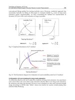
Fig. 13. Cross-Channel Correlation Cancellation Performances
Cancellation performances of the cross-channel correlation under room noise (WGN) are
obtained using the adaptive filter (AF2) and are shown is Fig. 13, where S/N is assumed to
be 20dB, 30dB and 40dB. In the figure
()
RL
CL dB is power reduction in dB which is observed
by the signal power before and after cancellation of the cross-channel correlation by AF2.
As shown here, more than 17dB cross-channel correlation cancellation is attained.
5.3 Echo canceller performances
To evaluate echo cancellation performances of the WARP acoustic echo canceller which
system is shown in Fig. 10, computer simulations are carried out assuming 1000tap NLMS
adaptive filters for both stereo and monaural echo cancellers. The performances of the
acoustic echo canceller are evaluated by two measurements. The first one is the echo return
loss enhancement ( )
ij
ERLE dB , which is applied to the WGN source case and is defined as
11
22
10 ,, ,,
00
(1) 1
11
22
10 ,, ,,
00
10log ( / )
ERLE
10log ( / )
FF
FF
NN
ijk MONijk
kk
Li j
NN
ijk STijk
kk
y
e MonauralEchoCanceller
y
e StereoEchoCanceller
(121)