Electric Vehicles The Benefits and Barriers Part 5 pdf
Bạn đang xem bản rút gọn của tài liệu. Xem và tải ngay bản đầy đủ của tài liệu tại đây (1.29 MB, 20 trang )
What is the Role of Electric Vehicles in a Low Carbon Transport in China?
69
3.1 Well-to-tank results
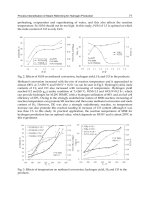
WTT fossil fuel consumption of each pathway was shown expect the 2 on-board hydrogen
generation pathways (Figure 1). No pathway consumed less WTT fossil fuel than the
conventional gasoline pathway when 1 MJ vehicle fuel was generated. The reason was that
present overall energy efficiencies of hydrogen production or electricity generation from
either coal or natural gas were between 40%~60%, which was much lower than the energy
efficiency of petroleum refining process (over 90%). Large central plant of hydrogen
production using natural gas as feedstock had the advantage of energy consumption by
350%~540% over other methods, indicating that this kind of central plant was likely a better
choice to make hydrogen than refill station production or on-board generation ways. Fossil
fuel required to produce grid electricity was about 6.3 times more than that required by the
conventional gasoline due to numerous coal utilization in power plant.
Fig. 1. Comparison of WTT fossil fuel consumptions
WTT greenhouse gas emissions resulting from fossil fuel consumption of each pathway was
presented expect 2 on-board hydrogen generation pathways (Figure 2). Greenhouse gas
emitted during hydrogen and electricity generation was 5~35 times higher than gasoline
production.
Fig. 2. Comparison of WTT greenhouse gas emissions
Electric Vehicles – The Benefits and Barriers
70
3.2 Well-to-wheel results
WTW fossil fuel consumption (Figure 3) and petroleum consumption (Figure 4) of total 12
pathways were described as how much MJ energy was required for the car to travel 1 km.
WTW energy consumptions of fuel cell vehicle pathways were very different due to
feedstock and process variety. The pathway of fuel cell vehicle using gaseous hydrogen
generated either from natural gas in large central plant or by on-board generator had a
comparable WTW fossil fuel consumption to the gasoline pathway, because the fuel
efficiency of fuel cell vehicles was higher the conventional gasoline vehicles. Electric vehicle
pathway using grid power consumed 10% less WTW fossil fuel than gasoline pathway,
because electric vehicles was more efficient than the conventional gasoline vehicles which
made great contributions to decrease WTW energy consumption.
Fig. 3. Comparison of WTW fossil fuel consumptions
Fig. 4. Comparison of WTW petroleum consumptions
Alternative fuels were able to largely substitute petroleum, and therefore import volume of
petroleum would be reduced and energy security of the country would be strengthened.
WTW petroleum consumption of fuel cell vehicle and electric vehicle pathways proved the
above theory (Figure 4). All 11 alternative fuel pathways used less than 1/3 petroleum of
the conventional gasoline pathway.
What is the Role of Electric Vehicles in a Low Carbon Transport in China?
71
WTW greenhouse gas emissions of different pathways were described as how much grams
of equivalent carbon dioxide (g eq. CO
2
) emission was emitted when the car travelled 1 km
(Figure 5). There were 2 fuel cell vehicle pathways that had lower WTW greenhouse gas
emissions than the conventional gasoline pathway. One was fuel cell vehicle with hydrogen
generated from natural gas by on-board generator (9% lower); the other one was fuel cell
vehicle with gaseous hydrogen produced from natural gas in large central plant (23%
lower). Besides, greenhouse gas emitted from electric vehicles using grid power was 12%
less than that from the conventional gasoline vehicle.
Fig. 5. Comparison of WTW greenhouse gas emissions
4. Conclusion
From the well-to-wheel study, we found that 1) the pathway of battery electric vehicle using
grid electricity had some advantage of both fossil fuel and petroleum consumptions and
greenhouse gas emissions. It could be concluded that plug-in hybrid electric vehicle that
was the combination of conventional gasoline vehicle and battery electric vehicle probably
held the same advantage; 2) for fuel cell vehicle, there were few pathways whose WTW
energy consumption and greenhouse gas emissions were comparable to the conventional
gasoline. So fuel cell vehicle pathways now had little advantage over both the conventional
gasoline vehicle and the battery electric vehicle.
Battery electric vehicle and plug-in electric vehicle should be given high priority when
China builds the low carbon transport system. Fuel cell vehicle would probably become a
promising way in the future. However, electric vehicles in China presently have to face
several key problems, such as the high cost of purchase, the absence of infrastructure
network, the disposal and recovery issues of batteries, and so forth. Hence, special follow-
up policies should be addressed to push the commercialization of electric vehicles in
China.
5. Acknowledgment
This work was supported by Ford Motor Company and BP Company.
Electric Vehicles – The Benefits and Barriers
72
6. References
Alternative Energy Program by National Development and Reform Commission.
(November 2006). Chinese Alternative Energy Research Report, National Energy
Administration, Beijing, China
Ministry of Science and Technology. (December 2010). 12000 New Energy Vehicles Been Put
into Operation in 13 Demonstrating Chinese Cities, January 2011, Available from:
National High Technology Research and Development Program (863 Program). (October
2010). Application Guideline for Key Technology and System Integration of Electric
Vehicle Program (Phase 1) in Modern Transportation Techonology Field, March 2011,
Available from:
Shen, W. (April 2007). Well-to-Wheel Analysis on Energy Use, GHG Emissions and Cost of Vehicle
Fuels in Future China [Doctoral dissertation], Tsinghua University, Beijing, China
Shen, W.; Zhang, A.; Han, W. & Chai, Q. (Octorber 2008). Life Cycle Assessment of Vehicle
Fuels, Tsinghua University Press, ISBN 978-7-302-18281-8, Beijing, China
Wallington, T.; Sullivan, J. & Hurley, M. (2008). Emissions of CO
2
, CO, NO
x
, HC, PM, HFC-
134a, N
2
O and CH
4
from the global light duty vehicle fleet. Meteorologische
Zeitschrift, vol. 17, No.2, (April 2008), pp. 109-116, ISBN 0941-2948
Xiao, B.; Chen, G. & Zhang, A. (2005). Life cycle assessment report of clean coal power technology,
Tsinghua University & China Coal Industry Clean Coal Technology Engineering
Research Center, Beijing, China
Yang, J. (April 2011). CO
2
reduction pathways of China transportation sectors under global
stabilization target [Doctoral dissertation], Tsinghua University, Beijing, China
5
Plug-in Hybrid Vehicles
Vít Bršlica
University of Defence in Brno
Czech Republic
1. Introduction
The plug-in hybrid vehicle (PHEV) represents the reaction of automotive industry on the
green policy, to reduce the pollutions and the fossil fuels consumption in transport. The oil
price is permanently rising and the oil import makes unpleasant dependence of the national
economy on the non-stabile countries, because the road transport is nowadays completely
dependent on the oil fuels. The electric drive is ready for use in the vehicles many years, it is
optimal for control and it offers the maximal efficiency, but there is no suitable battery
available in this time for all the day vehicle energy supply. But most of cars in household are
typically used in common commutation cycle, with average daily portion under 50km and
they are only occasionally used for longer trips in weekends or holidays. For such range is
the battery available with acceptable weight and price. If users do not like to hold and care
two cars, the electric one for commutation and the second one with petrol engine for longer
trips, the PHEV is an optimal solution, combining both drives and the suitable cooperation
between both power sources can give additional profit; also many materials and
components for the second car - body, wheels and suspension - are saved. However it must
be said that having better battery (or similar electrical energy storage device), the presence
of generator and internal combustion engine (ICE) is not necessary and the PHEV would be
reduced to the much simpler battery operated vehicle (BEV), although the running engine
produces some “free” heat which can be with advantage used for air-conditioning. The
green energy production from renewable power sources or from nuclear power plants
grows up and the night charging can solve the oil fuels reduction in the road transport.
2. History of EV and HEV
In the beginning of auto-mobility the electric drive was more successful, than engines with
internal combustion. The previous steam engines, very famous from railway locomotives,
were also not suitable for mobile lightweight applications, due to their big mass and the
need of water, which was permanently wasted in open system without condensation.
In the road passenger transport for very limited distance (due to low speed on roads for
horses) and for the sport activities was electric motor (EM) with a cheap lead acid battery
and simple speed control very reliable and easy operable. Looking in the historical records,
the first vehicle over 100km/h speed limit was electric vehicle and also the number of
registered vehicles with EM was equal to other kinds of drive. Only after the Ford’s mass
production of cheap vehicles with engine the ratio of electric vehicles decreases. Then with
Electric Vehicles – The Benefits and Barriers
74
better roads, growing speed and operating range consequently, the low battery capacity and
the slow long-lasting charging process beat in competition the electric vehicle in the road
transport. Only the cable supply was suitable to compete in the city transport (trolleybus)
and the battery supply remained only in low speed local transport, like door to door milk
and mail delivery, shipping in the production halls or in the railway stations, and in the last
decade also some golf carts and neighbourhood electric cars can be find in the market offer.
Fig. 1. Typical configuration of common hybrid vehicle with parallel power flow
Hybrid vehicles (HEV) with combination of engine and EM bring back the electric drive into
vehicle traction. They are on the market over ten years and their second generation is
offered now. First HEV were only from the Japanese production, but in last few years every
automotive production group presents at least one car with electric hybrid drive. Such
vehicle is certainly more expensive in manufacturing, but the advantage of HEV is its
reduced fuel consumption, primarily in the city cycle with low average speed, in which the
standard ICE vehicle has higher consumption (lower mileage), comparing with land
transport at much higher speed. Out of city the fuel savings are not detectable.
3. Hybrid vehicles
The typical HEV (Fig.1) has only low power EM, which assists in the phase of vehicle
acceleration and again in the braking, when it can recuperate the part of kinetic energy into
battery for the next acceleration. The efficiency of this cycle (braking – acceleration) is not
very good and about 50% of energy is lost, but in often repeating of this cycle at each traffic
lights, the fuel saving is important. The energy in one cycle is not big; therefore only small
battery can be used. The battery life in the number of cycles is very important, because it is
not acceptable to change this battery each month. Fortunately, the reduced depth of
discharge (DOD) extends the length of lifetime very much and this low ratio between the
energy of one cycle and the energy of the battery is the way, how to use one battery pack up
to five years with total number of cycles over 100 000.
The HEV principal scheme can be followed in Fig.1, where it can be observed the parallel
power ways from both torque sources to the wheel. The EM can work not only in motor run,
when it produces the torque and mechanical power from electric energy, but it can be easily
switched into generator run, when the mechanical power from kinetic energy of vehicle is
Fuel tank
ICE
Gearbox
Battery
EM
Red + Dif
Gearbox
Braking
Tor
q
ue
Recuperation
Plug-in Hybrid Vehicles
75
changed into electric energy, recuperated back to battery. The advantage of EM presence is
not only the energy recuperation, but also the torque production at any speed, like it was at
old steam engines. No kind of ICE is able to produce the torque at zero speed and moreover
there is some minimal value of crankshaft speed, called idle run, under which the ICE stops.
To keep the ICE in the idle run needs also some fuel and in city transport the standing at the
crossroads is very often and very long lasting. The engine stopping at any occasion and its
automatic starting connected with touch of clutch pedal, known as STOP-START system is
also effective, but it does not eliminate the energy wasting in brakes and the fuel
consumption for acceleration. Also the clutch wear is much higher than in the case of vehicle
accelerating by EM torque.
0
100
200
300
400
500
600
700
800
900
0 4000 8000 12000
Spe ed [RPM]
Torque [Nm]
TESLA
Lotus V
Lotus III
Lotus I
Fig. 2. Mechanical characteristics of EM vs. ICE with gearbox (r
III
=2, r
V
=4)
3.1 EM advantages
The comparison of EM and ICE mechanical characteristics is in Fig.2 and it can be said here,
that any EM can have the same characteristic if it is supplied from suitable inverter. Each
EM can be for short time overloaded, when increased current gives increased torque and the
torque is to disposal from zero speed. Also each kind of EM can recuperate the energy
working in generating mode, the negative (braking) torque reverses the current back to the
source. The speed gap between the zero and idle run speed of ICE can be reduced using the
variable-ratio gearbox. In the gearbox, when the speed is reduced, the torque grows up
inversely. The higher is the gear ratio, the lower is the speed and the higher is the torque
keeping the same power (neglecting losses). The mechanical power is given by:
P = T ω (1)
where T is the torque in Newton-meters and ω is angular speed in radians per second. The
common technical unit of speed n is revolve per minute, the transformation formula is:
ω = (2 π /60) n ≈ n/10
(2)
The gear ratio, according to (1) gives:
Electric Vehicles – The Benefits and Barriers
76
r = n
2
/n
1
= T
1
/T
2
(3)
From this mathematics and from Fig.2 there is evident, that at high speed the ICE has
always enough power, therefore it needs the help from EM2 primarily in the area of low
speeds, where the power is also small as results from (1). Low power EM and low power
battery are not able to drive the vehicle at speed over 10km/h. For fully electric drive the
concept must be modified.
4. Why plug-in hybrid?
Many car owner do not use the car for business travel, and they do not drive daily more
than 50km. for such distance it is not necessary to spend any petrol, because this distance
can be easily realized by energy from battery, but great disadvantage of electric drive is, that
the “empty” battery cannot be recharged in minutes and in the case of longer trip, the safety
return is not sure. Also in some rare trips during holidays etc. cannot be realized by electric
vehicle that means you must have or purchase another car. All these problems are solved by
serial hybrid with greater battery, which can be driven first 50km from battery only and in
the case of longer trip; the engine is started and operated in the optimal efficiency work
point with constant power and speed. The generated electricity is either used for motors
supply or in case of low load is simultaneously stored in empty battery.
The PHEV must be able to work in electric mode only at any speed, during the short trips
under the daily limit. Therefore it must have strong enough electric motor EM and this
condition results in serial concept hybrid, when the ICE is not mechanically connected with
wheels, because its help is not necessary (Fig.3).
Fig. 3. Typical configuration of PHEV with serial power flow
Omitting the generating unit in Fig.3, the PHEV is reduced into the simple BEV and only the
parameters of battery determine the operating range of this vehicle. The idea of hybrid
concept wants to eliminate the danger of empty battery in case of some complication in
traffic like detour, lost way, waiting, etc. Because the battery charging is supposed from
home plug during many hours and there are no charging stations in streets, the best way
how to be mobile permanently is to have the energy source for charging on the board. The
GEN
Inverter –
EM control
Battery
EM
Red + Dif
Gearbox
Fuel tank
ICE
Sw1
Plug-in Hybrid Vehicles
77
power of the charger does not have to be as big as is the EM power, because in the periods
with full power both sources, generator and battery, work together.
All the mechanical energy output from ICE is converted by generator into electricity, which
is typically divided between EM and battery, when EM does not work with full power. If
the EM is loaded more than is the maximal power from the generator can be, then the
battery must deliver the difference. It is typical in acceleration and in uphill slope, both lasts
only very short time in second or minutes. The ICE has not to be so strong (maximal power)
as it is in a petrol car and it can work here always near the optimal operating point (Fig.11)
with maximal efficiency and minimal emissions.
It is not the new idea to have the Engine-Generator unit on board, but to develop and realise
the mass production of PHEV it is a merit of American company Chevrolet (Fig.4). However
their vehicle is about three or four years in prototype and they solve intensively the problem
of optimal battery. The development and new inventions in this area are very fast and it is a
problem to start the production of any battery, if tomorrow some principally better
technology would appear.
Fig. 4. Chevrolet Volt Chassis Version 2008
But it is not only the batteries production technology, also the electric motor for traction
manufacturing needs new knowhow in the automotive industry. Also the manufacturers of
auxiliary components must prepare new products and some problem can create the
dangerous voltage in the vehicle, because the battery voltage can reach up to 300V and the
motor supply voltage AC up to 400V phase to phase or DC up to 600V. It is not the same
situation as is in traditional 12 or 24V and the isolation check in metallic body must be
perfect. But such systems are already developed and verified in trolleybuses e.g.
5. How to dimension the PHEV components
The problem of this PHEV concept (Fig. 3) is how to reach high efficiency of all the drive
train (ICE, Generator, Battery, Inverter, EM, Gear) for low power light vehicle with total
Electric Vehicles – The Benefits and Barriers
78
mass about 1500kg. Its average power out of highway at 80 or 90km/h limit is only 5 - 10kW
and the peaks are up to 100kW for dynamic drive in modern traffic. The situation in ICE
cars is more dependent on the engine volume. The same model can be sold with three or
more engines and each of them offers other dynamics. The power and the torque peaks are
in case of ICE fix and they can only decrease due the wear, not optimal intake parameters or
control, the EM is oppositely easily overload capable, of course for short time only, because
the overload brings higher losses and the temperature rise consequently. Big traction
machines have on their labels not only rated power but also one-hour power, which is 20 –
30% higher depending on the EM size. For vehicle acceleration in seconds the overload can
be easily 100% or more, because after this period the torque and current falls down and the
winding temperature also decreases back fast (with effective ventilation). From simulation
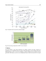
in Fig.5 it can be seen, the differences between the power in acceleration and in constant
speed drive for flat surface.
Fig. 5. Time dependence of Power, Speed and Distance for exemplar cycle
TESLA Roadster
0
10
20
30
40
50
60
70
80
90
0 50 100 150 200
Speed [km/h]
Power [kW]
Fig. 6. Power vs. speed for EV Tesla Roadster on the plane
Plug-in Hybrid Vehicles
79
The dependence of the power on the vehicle speed in steady state is in the Fig. 6 for strong
sport car Lotus, which is professionally remade by TESLA Cars Company for the electric
drive. Because at higher speed the aerodynamic drag represent the highest force, the power
grow with the speed is nearly quadratic Tesla Roadster has no generator, but it can be
interesting to compare it with two PHEV. The selected data of two typical PHEV are in
Table 1 briefly compared with top power BEV Tesla.
Mark Tesla Chevrolet Mitsubishi
Model Roadster Volt iMiEV
AC Motor 185kW 120kW 47kW
Maximal torque 375Nm 320Nm 180Nm
Asynchronous Asynchronous Permanent Magnets
Maximal speed 14.000rpm 7500rpm
Voltage 370V 320V 330V
Battery 56kWh 16kWh 16kWh
Mass 180kg
Generator NO 53kW
Maximal speed 200km/h 80/140km/h 130km/h
Maximal cruise 450km 64+960km 160 km
Vehicle mass 1080kg
80% SOC 30min
Table 1. BEV and PHEV parameters comparison
Fig. 7. Mitsubishi iMiEV through view
Electric Vehicles – The Benefits and Barriers
80
Chevrolet's Volt is the first series hybrid concept car shown by a major manufacturer. Its 1,0-
liter (1000ccm), 3-cylinder turbocharged engine runs an on-board 53kW generator that
recharges a 16kWh lithium-ion battery made of 80 four-volt cells. Main components
distribution on the chassis is in Fig.4. The engine-generator has typical handwrite of car
engineers and not only its size, but also its location under front hood with long exhaust
pipe. Guessingly 200kg mass can be replaced by another battery with more than twice
longer range. The small generator for occasional long trips could be situated in backside
trunk, or in tender, which could be hired. The fix mounting of ICE needs all the servicing as
standard ICE vehicle, oppositely to BEV, which needs no regular service. Because of rapid
evolution in battery technology GM newly opened advanced battery laboratories (3 000
square meters).
Opel Ampera is a Twin sister car to the Chevy Volt for European market. The other leading
European producers are preparing their program in EV. New producers like Fiskers,
Aptera, Th!nk and many other are only the small companies involved in EV development
and they can bring some revolutionary solutions, because there are strong restrictions, in big
companies, based on tradition.
Mitsubishi is leading Japan Company in preparing EV with lithium batteries. Its small car
iMi with ICE has its twin with electric drive, which is presently (2010) long-term tested over
all Japan. The main parts arrangement can be seen on Fig.7.
5.1 Motors
The EM choice is the most important part of PHEV design. As was mentioned above the EM
is easily overloadable, its power P depends on the voltage U and current I from the battery:
P = η U I
(4)
where η describes the motor efficiency. This power is equal to that one from (1). Very
simplified, it can be said, that the torque is given by the EM current and the EM speed is
given by voltage:
T = K Φ I
a
(5)
U
i
= K Φ ω (6)
These equation are exact for DC motor, where Φ is magnetic flux and I
a
is the armature
(or rotor) current and U
i
is induced voltage in the armature, which is slightly different
from the terminal voltage because of the voltage drop on the internal resistances. The AC
motors are more complicated, they have more phases, in case of induction (or
asynchronous) motor (AM) there is no separation of field circuit and armature circuit, but
it is not the main goal of this book and more can be find in any electric machines textbook.
The important for motor control is how to change the voltage, and in the case of AC
motors the frequency must be also changed (together with voltage), because instead of
mechanical current commutation in DC rotor, the switching technology must be used to
create the three phase system in converter. The output frequency f gives the speed of AC
rotor:
n
s
= 2 π f / p
(7)
Plug-in Hybrid Vehicles
81
where p is the number of pole pairs. The rotor of AM is slightly slower, that difference
between the speed of the rotating field n
s
and the real rotor speed n is called slip and its
value is typically 3 – 5%, changing with the load.
DC motors are the first kind of traction motors, and in the period before power electronics
their control was only by resistance controllers and serial-parallel switching. DC/DC
inverters improved the efficiency of DC motor in controlled drive, it is cheaper than the
DC/AC converter, but DC motor is not so robust and it needs often maintenance due to
carbon brushes.
Brushless DC is in principle the DC with permanent magnets (PM) for field creation on the
rotor and static electronic inverter, instead of collector with 3 segments on the rotor; it has 3
winding terminals on the stator, supplied from the 3-legs bridge, working as a commutator.
Because the rare earth PM (REPM) are very expensive and very sensitive, namely to
temperature and corrosion, they find place mostly in low power (0,2 – 2kW) EM for bikes,
where they are in low volume only.
In the power range 20 – 200kW for passenger cars the induction machine offers its perfect
robustness at low price and also the standard inverter supply, which widely used in
industry and also in new trams.
The switched reluctance machine (SRM) has also very robust and simple construction with
no rotor winding and it can be very prospective, but it is not yet widely used. It needs
special inverter, which supposes some larger volume production for a good price.
DC Brush Type
Brushless DC
(Permanent Ma
g
net)
AC
(Induction)
Peak efficienc
y
85 - 89 95 - 97 94 - 95
Efficienc
y
at 10% Load 80 - 87 73 - 82 93 - 94
Max. RPM 4 000 - 6 000 4 000 - 10 000 9 000 – 15 000
Cost per shaft kW $120 - 200 $120 - 180 $60 - 100
Relative Cost o
f
Controller 1 3 - 5 6 - 8
Table 2. Typical Electric Motors 20 – 200kW Parameters
The survey of EM basic properties is in Table 2. It must be said here, that all parameters in
this Table are valid for power range from 20 to 200kW and with growing power grows up
also the efficiency and oppositely the maximal speed falls down.
AC Motor DC Motor
Single-speed transmission Multi-speed transmission
Light weight Heavier at equivalent power
Less expensive More expensive
95% Efficiency at full load 85-95% Efficiency at full load
More expensive controller Simple controller
Motor/controller/inverter more expensive Motor/controller less expensive
Table 3. Electric Motors Properties Comparison
Electric Vehicles – The Benefits and Barriers
82
Another EM properties comparison can be read in Table 3 from the drivetrain design point
of view.
5.1.1 Motor volume
The volume and mass of EM is given by its torque and not by the power. Because the
vehicle mass should be minimized, the EM must be designed on maximal possible speed
and minimal torque consequently (1), of course with respect to efficiency and cooling ability.
Therefore no direct drive without gear is optimal and there is in Fig.3 the reduction and
differential gearbox between EM and wheel. Increasing the speed increases the frequency,
which should not exceed 400Hz. It is better to keep the frequency under 200Hz and for two
pole AM it can give the speed from (7) n
s
= 12 000rpm. For the vehicle speed 144km/h =
40m/s and the wheel circumference 2m its rotation speed n
W
is:
n
W
= 60 * 40 / 2 = 120rpm
(8)
Then the total ratio between the AM and the wheel must be from (3):
r
Total
= 120 / 12 000 = 1/100
(9)
which can be realised by 3 pairs of cogwheels minimally.
5.1.2 Motor losses
Beside of typical mechanical losses due to friction and ventilation losses, which both are
speed dependent, there are in the EM specific electrical losses and these can be divided into
two groups. The current depend losses, or Joule losses grow up with the square of current:
ΔP
J
= R
a
I
a
2
(10)
and looking in (5), they grow up with square of torque.
The other group of losses has origin in the magnetic circuit (iron) due its alternating flux.
These losses can be described by formula:
ΔP
Fe
= k m
Fe
Φ
2
f
1,6
(11)
where m
Fe
is the AC iron mass. The grow up with speed is more than linear, but if the EM
has not PM field, the flux can be reduced when there is no need of full torque (5) to reduce
the iron losses, but increased current results in the Joule losses grow up. The optimal flux at
any speed and power can be estimated. The greatest advantage of controlled flux is at high
speed and no torque run (by inertia or downhill), when the PM machine has high iron losses
and they are supplied from kinetic energy of vehicle, which means they are braking the
vehicle undesirably.
5.2 Battery and electrical energy storage
First EV has been built in the 1835 and 1836 respectively; the speed record 105km/h was
also reached with EV in 1899 with lead acid battery. Edison tried to build EV with his Ni-
Fe batteries, but without commercial success. From the year 1903 when Ford established
146km/h speed record, the petrol ruled the vehicles power supply, because of its very
high energy density, which is about 36MJ/L = 10kWh/L, because the petrol density is
only 0.72kg/L the mass density value is over 14kWh/kg. Also the charging power is
Plug-in Hybrid Vehicles
83
enormous, if filling the tank by speed 2L/s the 60L tank can be full in 30s and “supplying
power” is 72MW.
Comparing with liquid hydrocarbons, the best available batteries have only 0,2kWh in one
kilogram. There are some projects of better electric storage devices based on electrostatic
principle, but they are only in patents and no sample has been presented. In the
electrochemical batteries, the most promising are lithium-air, which can change completely
the electric vehicles during next ten years. Special problem of batteries with numerous cells
is their cooling (and heating) system keeping optimal temperature in all the battery pack
and the voltage distribution control (charge management) for in series cells avoiding
overcharging which can damage the cells with danger of explosion and fire.
Two parameters must be watched if looking for optimal battery, the energy density and the
power density. Survey of suitable batteries for EV is in Table 4.
Nearly all the 20th century there was no new chemistry in secondary cells (rechargeable)
introduced and only the technologies were improved in two basic batteries.
Lead-acid is wide spread battery for engines starting and for emergency power supply, the
Edison alkaline battery nickel – iron Ni-Fe was slightly improved by cadmium Ni-Cd. This
kind of batteries was mostly used for railway vehicles and communication technologies. The
silver based chemistry Ag-Zn was able to supply electric vehicle, but the silver is not widely
available (precious metal) and such batteries can be used only in very special purposes for
military or space technologies.
Lead-Acid (Ni-MH) Lithium-Ion
First Use
(Commercial)
1859 1989 1991
Current Use
(Automotive)
Traditional 12-volt
batteries
For today’s generation
of HEV
Under development
for PHEV and BEV
Strengths Long proven in
automotive use;
Price
Twice the energy/
weight as lead-acid
About twice the energy
content of Ni-MH
Weaknesses Heavy; low energy/
weight ratio for EV
High cost (four times
the cost of lead-acid)
Expensive until
production volume
Energy density 30 - 40Wh/kg 65 - 70Wh/kg 100 - 150Wh/kg
Recyclability Excellent Good Very Good
Table 4. Electrochemical Batteries Evaluation
Only the last decade of the 20th century and the new electronics devices, connected with
communication and information technologies, bring the progress in the cell chemistry.
The lithium ion and lithium polymer batteries replaced in few years the Ni-Mh in cellular
mobile phones, notebooks and other audio and video portable players. The Ni-Cd has
been also replaced in its last important area of use, which was hand-tools supply. This
new batteries generation has, up to three times, higher energy density, then old
chemistries, which give new possibilities for electric vehicle construction. Lithium is very
promising and many new prospective chemistries with lithium are invented and
developed, the survey is in Table 5.
Electric Vehicles – The Benefits and Barriers
84
Chemistry Company
Doped Lithium Nanophosphate A123
Manganese Spinel LG / NEC
Lithium Nickel Cobalt Aluminium
Oxide
Panasonic
Lithium Manganese Oxide Hitachi
Lithium Cobalt Oxide Commercial
offer
Lithium Titanate Spinel Altair Nano
Lithium Iron Phosphate Lishen
Lithium Manganese Titanate EnerDel
Table 5. Lithium Battery Chemistry Survey
The greatest problem of any battery for electric vehicle is beside its lifetime in cycles, but
also its low internal electric resistance, thermal stability between -40 to +60
◦
C, shock
resistance, non toxicity, fire safety, but mostly its charging properties and its price, which
can create important part of the vehicle price. For the car construction there is important also
the volume and mass energy density. The cheapest chemistry is the lead acid, which his
used in all cars for engine starting, but in electric vehicles only in old neighbourhood
vehicles and golf cars. The modern hybrids use Nickel – Metal Hydride chemistry or
Lithium, which is in strong development connected with communications and information
technology produced therefore only in small cells about 2Wh. Tesla Car Company started
the production of their BEV, which was designed few years ago with old technology lithium
battery consisting from 6 831 small cells a little bigger than AA size (8Wh each).
5.2.1 Charging
The big problem for EV is the long time for charging the battery, which is not comfortable
for permanent transport in business, comparing this time with gasoline filling, where the
entire tank can be filled in the time under one minute. The calculation of the power of such
filling results in megawatts. The fast charging brings not only the problems with battery
cooling, but also problem with power peaks in grid, because there are no reservoirs for
electrical energy (EE) similar to tanks for petrol and rapid charging results in high power
peaks:
P
Charge
[kW] = 60 Ek [kWh] / t [min] (12)
To charge 10kWh (which is equivalent energy of one litre petrol) in one minute, from this
formula, gives the charger power 600kW (!). Because the charging is not very efficient, and
more than 100kW are the losses – the heat, such rapid charging connected with energy
conversion is impossible. The only hope is here the storage of EE in electrostatic field, which
is not connected with energy conversion.
The rapid charging can be more effective if there is not required full charging. The partial
charging is described by SOC (state of charge) in percent of full capacity. Similarly is
defined the DOD (depth of discharge), which define the percent of full charge, which was
taken from battery and partial discharging extends the lifetime significantly.
Plug-in Hybrid Vehicles
85
The energy for charging is due to chemical processes much higher, than is the energy
received during discharge. It can be demonstrated on the lead acid cell, which is discharged
at 2V and for each 1Ah must be recharged 1,2Ah at voltage 2,4V. From this can be easily
calculated the efficiency:
η = 2 * 1 / (2,4 * 1,2) = 0,70 = 70% (12)
and similar value is valid also for the other chemistries.
5.2.2 Electrochemistry
Lead acid: The first in history secondary battery (1859), mass produced for ICE starting in all
vehicles, for emergency power supply and UPS (uninterruptible power supply), it is very
cheap, with number of full cycles about 400, but special construction for traction has
increased number of cycles to 2000. The sulphuric acid electrolyte is very corrosive and the
lead is only metal, which resists in this medium. The sealed construction and gel electrolyte
allow using this battery in any position without danger of stain or effusion. Its energy
density is up to 40Wh/kg, due its price it is very popular for EV drives, but the operating
range is very limited and the lifetime less than 5 or 10 years respectively. Another
disadvantage is the danger of sulphatizing, which can be prevented by immediate charging
after run that means the battery cannot be left discharged.
Nickel or Alkaline battery: The alkalic electrolyte with NaOH or KOH is less aggressive and
Edison realized the first alkaline secondary cell with Nickel and Iron electrodes so called Ni-
Fe battery. Nickel cadmium Ni-Cd is an improved chemistry with higher power density.
The voltage of cell is only 1.2V, but the lifetime of such battery with minimal maintenance is
about 20 years. It is mostly used in railway wagons and in hand tools. The toxic cadmium
was about 20 years ago (1989) successfully substituted by metal hydrides in so-called Ni-
MH cells, with better energy density. This chemistry is used in Japan HEV.
Fig. 8. Energy density in various battery chemistries
Na-MCl2 chemistry has similar parameters with Ni-MH and also Ni-Zn is from the same
family with similar gravimetric density but weaker volumetric density.
Lithium battery: Very reactive lithium has highest potential, but the technology was
mastered only in 1991 (by Sony). The lithium ion cells LiCoO2 with rated voltage 3.75V are
widely used in cellular phones and notebooks; the battery with serial connected cells must
Electric Vehicles – The Benefits and Barriers
86
have electronic balancing system to avoid the overcharge at any cell. In last few years the
big cells for traction are produced, with capacity up to 2 000Ah and new chemistry LiFePO4
(lithium iron phosphate) Table 5. Comparing to lead acid the fast discharge of lithium
battery does not decrease the capacity, but the energy is lower due to joule losses in internal
resistance.
The theoretical specific energy of lithium thionyl battery is 1 420Wh/L (explosive TNT has 1
920Wh/L) and the theoretical specific energy of lithium-oxygen is over 5 000Wh/kg, which
gives more traction energy than the petrol of the same volume or weight, if the ICE
efficiency is taken into account (Fig.8).
A lithium-titanate battery is a modified lithium-ion battery that uses lithium-titanate nano-
crystals on the surface of its anode instead of carbon. This applied nanotechnology gives the
anode a surface area of about 100 square meters per gram, compared with 3 square meters
per gram for carbon, allowing electrons to enter and leave the anode quickly. This makes
fast recharging possible and provides high currents when needed
Other chemistries: In last forty years after the renaissance of EV many new electrochemical
batteries have been studied, but they did not convince. High temperature NaS has good
parameters, but bad maintenance, Zn-Br needs two tanks for pumping electrolyte, which
stores the energy similarly as the vanadium battery, suitable more for stationary
applications. Special category is Ag-Zn chemistry with super performance, but due to
limited silver cannot be widespread system and it is used only in the very special military or
space applications.
5.2.3 Electrostatic storage
The super-capacitors (SC) are the first revolutionary technology, which can be compared to
electrochemical batteries in energy density and have much better power density, suitable for
the power peaks in short time.
Quantum Battery (QB) promises the surprising energy density, it is based on the discovery
of quantum effect on TiO
2
sample, measured by Swiss inventor and described in patent
application. The rutile crystals, 15nm long, absorb at 180V the energy with density 8 –
12MJ/kg. It is very optimistic, but without working prototype and with the theory of
photon resonance only. Author describes cheap technology with possible market price
15USD/kWh. The predicted low self-discharge (about 6,3 % per month) and long durability
would be optimal for EV.
EEStore from Cedar Park, TX, also announces the promising technology of high voltage
solid dielectrics super-capacitor based on thin layer (nanometers) with high permittivity
barium titanate composite. In the last period the power density 1200kJ/kg is referred, which
is four times more than electrochemical battery, moreover without looses and with short
recharging time less than one minute. But nanotechnologies in batteries with lithium
chemistry can be also competitive, as is mentioned above.
5.3 PHEV auxiliary components
As it is mentioned above, the absence of running ICE in PHEV means, there is no source of
thermal energy suitable for cabin heating. The heating as well as cooling, simply all the
cabin air condition can be realised by heat pump with electric drive, which must be
developed for next PHEV. The heat pump usage can save significantly the spending of
limited battery energy for non traction purposes.
Plug-in Hybrid Vehicles
87
There is also no mechanical drive of powered steering pump, powered braking without
running ICE and the modern car is supposed to have all these facilities, which must be
realised by local electric drives.
The lighting, dashboard and cabin electronics need low voltage supply, which must be also
realized by power electronics DC/DC inverter, instead of rotating generator.
All here listed components that must be developed for PHEV can later serve also for BEV,
when better battery will be available, but these components design, technology and
manufacturing must be realized and tested before starting the PHEV mass production.
6. Efficiency
The liquid hydrocarbons are optimal for transport due their extremely high energy density
when in 50kg tank can be stored 500kWh, it is of course the thermal energy, but if the total
efficiency (of all the energy conversion from fuel to heat, mechanical force on piston, torque
from crankshaft, via gearbox and axis to the wheels) is only 16 - 24%, as is calculated in
Table 6. Taking the middle value 20% there is the traction energy 100kWh to disposal. The
common passenger car with such petrol can run between 500 and 1000km. It is about
0,2kWh/km and for 60km must be in the battery more than 12kWh.
In the Table 6 is the survey of all components of drive train with typical efficiencies and for
more vehicles and operating modes is the total efficiency calculated. From first two rows is
evident, that the classical petrol car in city transport has 50% increased fuel consumption,
because its engine works with lower efficiency at low power (Fig.11). The new symbols in
Table 6 are MGB for manual gearbox, REC for AC/DC inverter (rectifier), INV for DC/AC
inverter and RDG for reduction and differential gearbox.
The PHEV without ICE has efficiency 77% if calculated from the battery energy, but only
54% if calculated from the plug. If the PHEV charges its battery from running ICE, its total
efficiency can fall under the classic vehicle in the city traffic and if its ICE will be used only
for EM supply its efficiency is still under the classic vehicle. Last example in the table is for
Diesel – electric drive on big locomotive (Fig.9), where due better efficiencies of big power
components is also the total efficiency satisfactory.
ICE GEN MGB REC BAT INV EM RDG TOTAL
Classic Car 0,30 0,85 1,00 0,95
0,24
Classic Car - City 0,20 0,85 1,00 0,95
0,16
PHEV - Electric 0,95 0,85 0,95
0,77
PHEV - Electric 0,70 0,95 0,85 0,95
0,54
PHEV – Charging BAT 0,30 0,85 0,95 0,70 0,95 0,85 0,95
0,13
PHEV – No Charging 0,30 0,85 0,95 1,00 0,95 0,85 0,95
0,19
Loco D-E - 1MW 0,38 0,90 0,95 1,00 0,95 0,90 0,95
0,26
Table 8. Efficiency of Drive Train for Various Vehicles
6.1 Diesel-electric transmission
Diesel electric transmission is effectively used in locomotives for rail transport, but there is
no energy accumulator in the power train and the generator – inverter – motor (Fig.9) works
Electric Vehicles – The Benefits and Barriers
88
here as an alternative to mechanical shafts and gearboxes, with better flexibility and high
efficiency. It is also the rated power of components, which gives the nice efficiency, because
the motors are in the power 100 – 1000kW. The greater rated power the higher efficiency is
standard property of every machine.
Fig. 9. Typical configuration of Diesel – Electric Locomotive (serial power flow)
If the PHEV would be, after spending the energy accumulated in battery from the grid,
operated similar way as this diesel – electric loco without charging the battery from engine
and the battery would be used only in the same mode as is in actual HEV, that means for
accumulating of kinetic energy during recuperative braking, the electric power train
efficiency has not be so bad.
From this locomotive can be also copied the multi-motor scheme when each axis has one
EM. For road vehicle it can be the advantage if any wheel has its motor, but small motors
are again less efficient. Possible solution can be the drive management with switching-off
the motors at constant speed, when the individual EM for each wheel allows the optimal
regenerative braking with ABS control, preventing the wheel blocking, because every wheel
torque and speed can be controlled separately. The storage system can return the energy
from braking into next acceleration and reduce the energy consumption, but it is similar as
in standard hybrid, when greater battery capacity allows to store not only the energy from
one acceleration - deceleration cycle, but also (in mountainous countries) to exploit the
potential energy from downhill drive for next uphill climb.
6.2 HEV efficiency
What is the fuel savings composition in HEV is briefly explained in Fig.10, where the
negative influence of increased vehicle mass (battery + EM) represents the first column. The
next three columns are contributions from HEV technology given by no ICE idle run, ICE
speed control and EE recuperation by electric braking.
The standard HEV as is in Fig.1 saves the fuel only in the city traffic. The ICE specific fuel
consumption is in Fig.11 and it is evident, that for the torque under 15% of rated value, the
fuel consumption grows more than twice.
EM 1
GEN
Reduction
Gearbox
ICE
EM 2