Ferroelectrics Applications Part 10 pot
Bạn đang xem bản rút gọn của tài liệu. Xem và tải ngay bản đầy đủ của tài liệu tại đây (2.96 MB, 23 trang )
2 Ferroelectrics
the organic films (Ma et al., 2004). The bending characteristics of the resistive-type
nonvolatile polymer memory device fabricated on the poly(ethylene terephthalate) were well
demonstrated (Ji Y. et al., 2010). In place of organic layers, binary oxide thin-films which
can be deposited at low temperature were also employed for the resistance change operation
(Lee S. et al., 2009; Seo J. W. et al., 2009). The feasibility for the three-dimensional stacked
memory concept was also introduced by implementing one-diode (CuO/InZnO)-one-resistor
(NiO) storage node with InGaZnO (IGZO) thin-film transistors (Lee M. J. et al., 2009).
Charge-injection has also been utilized for the nonvolatile memory operation, for which
specified device structures such as organic bilayers (Ma et al., 2002) or nanoparticle-embedded
organic layers (Leong W. L. et al., 2009) have been proposed. Organic thin-film transistor
having a floating-gate for charge storing is one of the most typical memory transistors
fabricated on the plastic substrates (Baeg K. J., 2010; Wang W. et al., 2009). On the other hand,
the ferroelectric-based field effect transistor (FeFET) have features that remnant polarization
of ferroelectric gate insulator can be employed for the nonvolatile memory actions (Kang S.
J. et al., 2009a; Lim S. H. et al., 2004). Although each device configuration has pros and cons,
the practical memory array embeddable into the flexible electronic systems have not been yet
commercialized.
Tracing the nonvolatile memory technologies in Si-based electronics back to 1990s, the FeFET
was one of the most promising devices replacing the conventional flash memory facing
physical scaling limitations at those times. However, the crosstalk for random accessibility
and short data retention time of the FeFET were concluded to be fatal drawbacks for the
mass-production, although it successfully claimed the ultimate scalability and nondestructive
readout characteristics. Unlike these situations in the Si-based electronics demanding an
ultra-high specifications and an aggressive device scaling, the requirements for the nonvolatile
memory devices integrated into the large-area electronics including the flexible systems are
considerably different. In these fields, low-cost and stable operation would be more important
factors than the high performances. From this viewpoint, the ferroelectric field-effect thin-film
transistor employing a polymeric ferroelectric material, instead of oxide ferroelectrics, can be
a very promising candidate because it can be operated in a very reproducible way with a
definitely designable operation principle and be fabricated by a very simple process. In this
chapter, we propose the organic/inorganic hybrid-type plastic memory transistor exploiting
the ferroelectric field effect with the gate stack structures of ferroelectric copolymer gate
insulator and oxide semiconducting active channel. Our device concept and features of
ferroelectric copolymer-based memory transistor will be proposed in Section 2. The device
characteristics and nonvolatile memory behaviors of the proposed plastic memory transistors
are demonstrated and the remaining technical issues to solve for future practical applications
are picked up. This approach will provide a special meaning to expand the ferroelectric nature
to the next-generation large-area electronics.
2. Flexible ferroelectric memory
As mentioned above, the single-transistor-cell-type memory transistors composed of a
ferroelectric gate insulator (GI) have been extensively investigated for the conventional Si
electronics so far, in which various oxide ferroelectric materials such as Pb(Zr,Ti)O
3
(Shih W.
C. et al., 2007; Tokumitsu et al., 1997), SrBi
2
Ta
2
O
9
(Horiuchi et al., 2010; Tokumitsu et al.,
1999; Yoon S. M. et al., 1999), (Bi,La)
4
Ti
3
O
12
(Aizawa K. et al., 2004; Lee N. Y. et al., 2003),
196
Ferroelectrics - Applications
Ferroelectric Copolymer-Based Plastic
Memory Transistos 3
PbGeO
3
(Li T. et al., 2003), YMnO
3
(Ito D. et al., 2003), LiNbO
3
(Kim K. H., 1998), and BiFeO
3
(Lin C. et al., 2009) have been chosen as the ferroelectric GI. However, in realizing the plastic
nonvolatile memory array, the use of oxide ferroelectric GI is absolutely unfavorable owing
to the high crystallization temperature which is typically higher than 650
C. The overall
process temperature should be suppressed below 200
C. Although some encouraging reports
on the novel transfer technique (Roh J. et al., 2010) and ultra-low temperature process (Li J.
et al., 2010) for the oxide ferroelectric thin films have recently been published, to secure the
high-quality oxide ferroelectric GI for the memory transistor with low temperature process is
still very challenging. From this background, the employment of polymeric ferroelectric thin
film can offer an attractive solution to this problem because its crystallization temperature is
much lower than those of the oxide ferroelectrics. Poly(vinylidene fluoride-trifluoroethylene)
[P(VDF-TrFE)] is the most typical ferroelectric copolymer material (Furukawa T., 1989; Nalwa
H. S., 1995). It shows superior properties of a relatively large remnant polarization, a
short switching time, and a good thermal stability when it is compared with other organic
ferroelectric materials such as odd-nylon, cynopolymer derivatives, polyurea, ferroelectric
liquid crystal polymers (Nalwa H. S., 1995). The melting temperature, Curie temperature,
and crystallization temperature are changed with the composition of PVDF and TrFE. For the
composition of 70/30 mol% for the P(VDF-TrFE), those properties are known as 155
C, 106
C, and 129
C, respectively. The remnant polarization (P
r
) and dielectric constant are in the
ranges from 8 to 12 C/cm
2
and from 12 to 25 , respectively, depending on the composition
(Nalwa H. S., 1995). P(VDF-TrFE) thin film can be simply formed by a solution-based
spin-coating method and be crystallized at a lower temperature around 140
C, which is one
of the beneficial merits in realizing the memory device on the plastic substrate.
So far, most works on the fabrication and characterization for the nonvolatile memory
transistors using the P(VDF-TrFE) have been mainly investigated for realizing the all-organic
memory transistors with organic semiconducting channel layers. Various organic active layers
such as the evaporated pentacene (Kang S. J. et al., 2008; Nguyen C. A. et al., 2008; Schroeder
R. et al., 2004), soluble pentacene (Kang S. J. et al., 2009a;b), and solution-processed polymeric
semiconductors (Naber R. C. G. et al., 2005a;b) were chosen and the memory thin-film
transistors were demonstrated. Actually, it is the case that the employment of organic channel
can be very suitable for low-cost disposable applications with a lower specification. However,
the weaknesses of a low field-effect mobility, a unsatisfactory ambient stability, and a difficult
device integration with the organic-based transistors seriously restrict the real application of
this kind of memory TFT within narrow limits. A powerful alternative for enhancing and
stabilizing the device performance is to utilize the oxide semiconductor such as ZnO and
IGZO, which is one of the most important features of our proposed plastic memory transistor.
The oxide semiconductor-based TFTs present such beneficial features as high field-effect
mobility, excellent uniformity, and robust device stability (Hoshino K. et al., 2009; Jeong J. K.
et al., 2008; Nomura et al., 2004). As results, the oxide TFTs have attracted huge interest as one
of the most promising backplane device technologies for the next-generation liquid-crystal
display (LCD) (Osada T. et al., 2010) or organic light-emitting diode display (OLED) (Ohara H.
et al., 2010; Park J. S. et al., 2009) with a large size and a high resolution. A transparency of the
oxide semiconductor to the visible light can be another benefit of expanding the applications
to the transparent electronic devices (Park S. H. et al., 2009). These features can be similarly
applied for the ferroelectric-based plastic memory transistors. Because the oxide channels
are patterned into only small gate areas on the substrate, a relatively brittle nature of oxide
197
Ferroelectric Copolymer-Based Plastic Memory Transistos
4 Ferroelectrics
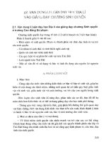
Fig. 1. Typical example of a schematic cross-section diagram for the proposed plastic
memory TFT.
Fig. 2. Schematic views on the operating origin for the nonvolatile memory behaviors of the
ferroelectric field-effect-driven memory TFT. When the oxide semiconductor is considered to
be n-type, positive and negative programming voltage are initially applied to the gate
terminal for (a) on and (b) off operations, respectively.
thin-film will be no longer a fatal problem for the flexible electronic devices. The use of oxide
channel for the plastic memory TFT is also preferable in the viewpoint of integrating the
full-scale memory array with memory cells and peripheral driving circuit. Because the oxide
TFTs are very suitable devices composing the circuit components, we can design the process
using common oxide channels for both the memory and driving TFTs. On the basis of the
considerations discussed above, the combination of an organic ferroelectric gate insulator and
an oxide semiconducting channel will be the best choice for the high performance nonvolatile
memory transistors embeddable into the various electronic systems implemented on the
large-area flexible plastic substrate.
Figure 1 shows a typical schematic cross-sectional view of our proposed plastic memory TFT,
which was designed to be a top-gate bottom-contact configuration. Because the P(VDF-TrFE)
is vulnerable to the plasma-induced deposition process for the oxide channel layer, the
bottom-gate configuration is very difficult to be fabricated with an excellent interface between
the P(VDF-TrFE) and oxide semiconductor. Furthermore, in order to enhance the device
performances, the post-annealing process is sometimes performed at a temperature higher
than 200
C after the deposition of oxide channel. However, the available thermal budget
after the formation of P(VDF-TrFE) is restricted to below 150
C for the bottom gate structure
owing to the low melting temperature of the P(VDF-TrFE). The interface controlling layer in
the top-gate structure, as shown in the figure, is very desirable to be introduced between the
P(VDF-TrFE) and oxide channel layer. In this work, a very thin Al
2
O
3
layer deposited by
198
Ferroelectrics - Applications
Ferroelectric Copolymer-Based Plastic
Memory Transistos 5
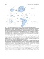
Fig. 3. Flowchart of fabrication procedures for the proposed plastic memory TFT, in which
the process steps were designed to use four photomasks. All processes were performed
below 150
C.
atomic-layer deposition (ALD) method was prepared for the device fabrication. This interface
controlling layer is very effective for protecting the channel surface during the coating and
etching processes of the P(VDF-TrFE) GI layer. Chemical solvents of the P(VDF-TrFE) solution
and/or oxygen plasma environment employed for the P(VDF-TrFE) patterning process might
degrade the electrical natures of the oxide channel layers. The operating origin for the
nonvolatile memory behaviors of the proposed memory TFT can be explained by simple
schematics shown in Fig. 2. When the positive gate voltage is applied, the ferroelectric
polarization of the P(VDF-TrFE) aligns downward and hence the large drain current flow in
the n-type oxide channel layer between the source and drain terminals. Because the aligned
polarization remained even after the removal of the gate voltage, the programmed drain
current can be detected when the drain is biased. This is the memory on state. On the other
hand, after the negative gate voltage is applied, the polarization aligns upward, and hence
the device doesn’t flow the current through the channel. This is the memory off state. The
programmed data can be nondestructively readout in the shape of drain current, because
the read-out signals are so chosen as not to reverse the direction of pre-aligned ferroelectric
polarization. In order to guarantee the good memory operations of the proposed memory
TFT, it is very important to carefully design and optimize some parameters of thicknesses in
the interface controlling and oxide channel layers. The detailed strategies can be referred
in our previous investigation (Yoon S. M. et al., 2009a). We previously demonstrated the
feasibility of our proposed memory TFTs fabricated on the glass substrate. The excellent
device characteristics of the memory TFT using P(VDF-TrFE) GI and IGZO active channel
was successfully confirmed, in which a thermal budget for overall process was 250
C (Yoon
S. M. et al., 2010a). The fully-transparent memory TFT using Al-Zn-Sn-O active channel was
fabricated to have the transmittance of approximately 90% at a wavelength of 550 nm (Yoon
S. M. et al., 2010b). Write and read-out operations of the two-transistor-type memory cell
composed of one-memory and one-access oxide TFTs, which was integrated onto the same
substrate, were also demonstrated (Yoon S. M. et al., 2010c). In this work, we will focus on
the fabrication and characterization of the flexible nonvolatile memory TFT prepared on the
plastic substrate.
199
Ferroelectric Copolymer-Based Plastic Memory Transistos
6 Ferroelectrics
3. Experimetal details
Poly(ethylene naphthalate) (PEN, Teijin DuPont) was selected as a substrate owing to
its low coefficient of thermal expansion, strong chemical resistance, and low-cost for the
device fabrication. Firstly, barrier against the out-gassing and surface planarization layer of
ALD-grown Al
2
O
3
was prepared onto the bare PEN substrate. Ti/Au/Ti film was deposited
by electron-beam (e-beam) evaporation and patterned into the source/drain electrodes on
the 200-m-thick PEN by lift-off process. Top and bottom layers of Ti worked as good
ohmic contact with oxide channel layer and good adhesion with the substrate, respectively.
10-nm-thick ZnO film was chosen as an oxide semiconducting channel for the plastic
memory TFT, which was deposited by plasma-enhanced ALD method at 150
C using
diethylzinc and O
2
plasma as the Zn and oxygen sources, respectively. Then, 6-nm-thick
Al
2
O
3
interface controlling layer was successively deposited by ALD method at 150
C
using trimethylaluminium and water vapor as the Al and oxygen sources, respectively.
After the Al
2
O
3
and ZnO were patterned into the channel areas using dilute hydrofluoric
acid solution, thermal treatment was performed at 150
C to enhance the ZnO channel
properties. P(VDF-TrFE) layer was formed by spin-coating method using a 2.5 wt% dilute
solution of P(VDF-TrFE) (70/30 mol%) in methyl-ethyl-ketone. A solution was spun on the
substrate at a spin rate of 2000 rpm and then dried at 70
C for 5 min on a hot plate. The
prepared film was crystallized at 140
C for 1 h in an air ambient. The film thickness of
P(VDF-TrFE) was measured to be approximately 150 nm. Via-holes were formed by O
2
plasma
etching of the given areas of P(VDF-TrFE) layer using a dry etching system, in which the
lithography processes including the developing and stripping of photoresists coated on the
P(VDF-TrFE) layer were so carefully designed as not to make undesirable chemical damage
to the P(VDF-TrFE) (Yoon S. M. et al., 2009b). Finally, Au film was deposited by e-beam
evaporation and patterned as gate electrode and pads via lift-off process. The process flow and
the detailed conditions were summarized in Fig. 3. Figures 4(a) and (b) show a photograph
of the process-terminated PEN substrate and a typical photo-image of the substrate under a
bending situation, respectively. The size of the test-vehicle processed on the PEN substrate
was 2
2cm
2
. The microscopic top view of the memory TFT fabricated on the PEN substrate
was shown in Fig. 4(c). All the electrical characteristics including programming and retention
behaviors of the fabricated plastic memory TFT were evaluated in a dark box at room
temperature using a semiconductor parameter analyzer (Agilent B1500A). The variations
in their characteristics under the bending situation with a given curvature radius (R ) were
measured by setting the configuration, as shown in Fig. 4(d).
4. Device evaluations
4.1 Bending characteristics of ferroelectric P(VDF-TrFE) capacitors
In advance, the basic ferroelectric behaviors were investigated for the P(VDF-TrFE)
capacitors which were fabricated with the TFTs on the same substrate. Figure 5(a) and
(b) show a schematic cross-sectional diagram and a top-view of optical microscope for
the Au/P(VDF-TrFE)/Au capacitors. Patterned P(VDF-TrFE) film was accurately defined
between the top and bottom electrodes with the capacitor size of 25
25 m
2
. The
polarization-electric field (P-E) characteristics of the ferroelectric capacitor were measured as
shown in Fig. 5(c), in which the E was modulated from 0.45 to 1.80 MV/cm. Typical values
200
Ferroelectrics - Applications
Ferroelectric Copolymer-Based Plastic
Memory Transistos 7
Fig. 4. (a) A Photograph of the PEN substrate on which the test devices were fabricated. (b) A
typical photo image of the PEN substrate under a bending situation. The substrate size is
2
2cm
2
. (c) Microscopic top view of the fabricated memory TFT with the structure of
Au/P(VDF-TrFE)/Al
2
O
3
/ZnO/Ti/Au/Ti/Al
2
O
3
/PEN. The channel width and length are
40 and 20 m, respectively. (d) A photo image of electrical evaluation for the fabricated
device when the PEN substrate was bent with R of 0.65 cm.
Fig. 5. (a) A Schematic cross-sectional diagram and (b) a microscopic image of the evaluated
P(VDF-TrFE) capacitors fabricated on the PEN substrate. The patterned capacitor size was
25
25 m
2
. (c) A typical P-E characteristics of the P(VDF-TrFE) capacitors fabricated on the
PEN substrate at the frequency of 1 kHz. (d) Polarization saturation behavior with the
increase in the E applied across the capacitor at various signal frequencies from 10 Hz to 100
kHz.
201
Ferroelectric Copolymer-Based Plastic Memory Transistos
8 Ferroelectrics
of the remnant polarization (P
r
) and coercive field (E
c
) were obtained to be approximately
9.1 C/cm
2
and 522 kV/cm, respectively, at the measuring signal frequency of 1 kHz. The
polarization saturation behaviors with the increase of the E applied across the ferroelectric
film were also examined at various signal frequencies from 10 Hz to 100 kHz, as shown in
Fig. 5(d). The E required to obtain the full saturation in the ferroelectric polarization was
observed to decrease with the decrease in signal frequency, which is related to the fact that the
memory operations of the proposed plastic memory TFT may be influenced by the duration of
programming voltage signals as well as the signal amplitudes (Furukawa T. et al., 2006; 2009;
Yoon S. M. et al., 2010d). It can be said that these obtained characteristics were almost similar
to those for the P(VDF-TrFE) capacitors fabricated on the Si or glass substrate, even they were
prepared on the flexible PEN substrate.
It is very important to investigate the variations in electrical properties of the fabricated
capacitors when the substrate was bent with a given curvature radius (R). In these
measurements, the R was set to be two values of 0.97 and 0.65 cm, as shown in Figs. 6(a)
and (b), respectively, which visually show the bending situations of the substrate. Figures 6(c)
and (d) show the P-E ferroelectric hysteresis curves of the same device examined in Fig. 5
when the R’s were 0.97 and 0.65 cm, respectively. There was no problem in obtaining the
ferroelectric polarization for the P(VDF-TrFE) capacitors even under the bending situations.
The detailed variations with the changes in R can be confirmed in Fig. 7(a), in which P- E
curves obtained at the same field for the bending situations with different R’s were compared.
The P
r
was varied to approximately 9.6 C/cm
2
when the R decreased to 0.65cm, which
correspond to the increase by 5% compared with the case when R was infinite (). However,
this small increase in P
r
can be explained by the increase in leakage current component for
the examined device owing to the repeated evaluations under a high electric field. As a result,
it can be suggested that the capacitor did not experience a significantly remarkable variation
in the ferroelectric properties. On the other hand, the E
c
was measured to be approximately
528 and 588 kV/cm when the R was set to be 0.97 and 0.65 cm, respectively. Although it was
observed that there was an approximately 13% increase in E
c
when the substrate was bent
with R of 0.65 cm, it is likely that this does not originated from the mechanical strain induced
by the substrate bending. The detailed effects of the bending R on the polarization saturation
behaviors were examined as shown in Figs. 7(c) and (d) at two signal frequencies of 10 Hz and
10 kHz, respectively. It is very useful to introduce a parameter of E
hp
in order to quantitatively
compare the obtained characteristics for the different bending situations. The E
hp
was defined
as the electric field required for securing the half point of full saturation of ferroelectric
polarization (0.5P
r
) at a given signal frequency. For the signal frequency of 10 Hz [Fig. 7(c)],
the E
hp
’s for the various R’s of , 0.97, and 0.65 cm were estimated to be approximately 0.38,
0.41, and 0.44 MV/cm, respectively. On the other hand, at the signal frequency of 10 kHz
[Fig. 7(d)], the E
hp
’s were approximately 0.67, 0.72, and 0.81 MV/cm for the same situations.
These observations might indicate that the polarization switching at initial phase for the
lower electric field was impeded when the P(VDF-TrFE) film was bent, and that the extent
of impediment was larger for the cases of larger R and higher signal frequency. However,
these kinds of evaluation are sometimes very tricky and controversial. It was also observed
that the E
hp
showed larger values when the substrate was restored to the initial flat status
(R=) compared with those for the R of 0.65 cm, as shown in Figs. 7(c) and (d). Consequently,
it can be concluded that the larger impediment in polarization switching event, which was
mainly observed for the larger R, was dominantly affected by the ferroelectric fatigue, even
202
Ferroelectrics - Applications
Ferroelectric Copolymer-Based Plastic
Memory Transistos 9
Fig. 6. P-E characteristics of the Au/P(VDF-TrFE)/Au capacitors when the substrate was
bent with different R’s of (a) 0.97 and (b) 0.65 cm. The bending situations of each case are
shown in photos. The measurement frequency was set to be 1 kHz.
though some parts of degradation caused by the mechanical strain at the bending situation
cannot be completely ruled out. It gives more detailed insights to investigate the bending
characteristics of the device with different capacitor size, as shown in Fig. 7(b), because the
mechanical strain is differently induced for the capacitors with different size even for the
same R. According to the obtained characteristics for the P(VDF-TrFE) capacitors with the
size of 200
200 m
2
, there was not any marked variation in the behaviors except for the
small increase in E
c
with the decrease of R. It suggests that the polarization saturation
behaviors behaved in a very similar way to those discussed above for the 25
25-m
2
-sized
capacitor even for the larger capacitor size. We can found from these discussions that the
mechanical strain applied to the P(VDF-TrFE) capacitors under the bending situations did not
make any critical influence on the ferroelectric properties, which is in a good agreement with
the previous reports (Matsumoto A. et al., 2007; Nguyen C. A. et al., 2008). However, the
data reproducibility and further investigations should be also performed with smaller R to
accurately verify the bending effects on the device as future works.
4.2 Memory behaviors of flexible memory TFT
Based on the basic ferroelectric properties of the P(VDF-TrFE) capacitors fabricated on the
PEN substrate, the device characteristics of the fabricated memory TFT were extensively
investigated. Figure 8(a) shows the drain current-gate voltage (I
D
-V
G
) transfer characteristics
of the plastic memory TFT at the various sweep range in V
G
, which were measured with a
double sweep mode of forward and reverse directions at V
D
of 5.0 V. The gate width (W)
and length (L) of the measured device were 40 and 20 m, respectively. As can be seen in
the figure, we could obtain sufficiently good device performances, in which the 8-orders-of
203
Ferroelectric Copolymer-Based Plastic Memory Transistos
10 Ferroelectrics
magnitude on/off ratio and the subthreshold swing (SS) of 650 mV/dec were successfully
obtained. Counterclockwise hystereses of the transfer curves which originated from the
ferroelectric field effect were clearly observed. A 3.4 V-memory window was obtained at
the V
G
sweep range from -10 to 8 V. Gate leakage currents could be suppressed to be
lower than 10
11
A, even though the device was fabricated on the plastic substrate using
low-temperature processes below 150
C. It was confirmed that the transfer characteristics
did not change between the first and the second sweep in V
G
, as shown in Fig. 8(b).
This is also an important point considering the fact that the transfer curves of this kind of
memory TFT are markedly fluctuated if the fabrication processes are not optimized for the
device. Although only twice repetitive measurements of transfer curves cannot guarantee the
endurance in device performance, the undesirable variations in device characteristics during
the repetitive operations could be easily examined even by performing only two successive
sweeps. Therefore, it can be concluded that the proposed plastic memory TFT was well
fabricated on the PEN substrate without any critical damages caused by fabrication processes.
The bending characteristics were also investigated for the same device, in which two kinds
of measurements were performed. The first one is to examine the changes in device
behaviors at the situations of substrate bending with a given R, which can be called as
”bending durability”. The second one is to evaluate the degradation in device performance
after the given numbers of repetitive bending operation, which can be called as ”bending
fatigue endurance”. Figure 9(a) shows the bending durability by measuring the transfer
characteristics when the substrate was bent with the R of 0.97 cm. As can be seen in the figure,
the plastic memory TFT did not experience so marked variations in its device behaviors. The
change in memory window at the bending situation was approximately 0.7 V at most. It
was also very encouraging that the bending fatigue endurance test with 20,000 cycles did not
make any critical degradation in its characteristics, as shown in Fig. 9(b). In this evaluation,
bending fatigue was intentionally loaded by using the specially-designed bending machine
shown in Figs. 9(c) and (d), in which the R was set to be 2.35 cm. These results indicate that
the proposed plastic memory TFT fabricated on the PEN can be utilized under the bending
situations for any flexible devices. Although the R could not be reduced to smaller state owing
to the substrate size and machine specification in this work, further investigations would
be necessary when the device is repeatedly bent for larger number of bending at smaller R.
Actually, we have to check the observation that a very small reduction in the memory window
was observed as the increase in the number of bending.
Finally, the programming and retention behaviors of the fabricated plastic memory TFT were
evaluated, as shown in Fig. 10. These characteristics are very important for actually employing
the nonvolatile memory component embedded into the large-area flexible electronic systems.
The programming events for the on and off states were performed by applying the voltage
pulses of 6 and -8 V, respectively. The pulse width was varied to 1 s and 100 ms in order
to estimate the relationship between the available memory margin and the programming
time. Both memory states were detected by measuring the I
D
at a read-out V
G
of0V.The
memory window in transfer curve for the memory TFT, which was obtained to be located
with centering around0VinV
G
[Fig. 8], is a very beneficial property, because the read-out
and retention operations for the stored information can be carried out at 0 V. For the case
of 1 s-programming, the on/off ratio was initially obtained to be approximately 6.6
10
5
and
it decreased to approximately 130 after a lapse of 15000 s. On the other hand, for the case
of 100 ms-programming, the initial on/off ratio was only 8.0
10
3
and the memory margin
204
Ferroelectrics - Applications
Ferroelectric Copolymer-Based Plastic
Memory Transistos 11
Fig. 7. Comparisons of the P-E characteristics of the fabricated capacitors with the size of (a)
25
25 m
2
and (b) 200200 m
2
when the R was varied to , 0.97 and 0.65 cm. For the case
of 25
25 m
2
-sized capacitor, the polarizarization saturation behaviors were investigated at
the signal frequencies of 10 Hz and 10 kHz when the R was varied to , 0.97, 0.65 cm and
restored to initial state.
Fig. 8. (a) Sets of I
D
-V
G
transfer curves and gate leakage currents of the fabricated
nonvolatile plastic memory TFT fabricated on the PEN substrate when the V
G
sweep ranges
were varied. (b) Variations of transfer characteristics of the same device between the first and
the second sweeps in V
G
. The V
D
was set to be 5 V. The channel width and length of the
evaluated device was 40 and 20 m, respectively.
205
Ferroelectric Copolymer-Based Plastic Memory Transistos
12 Ferroelectrics
Fig. 9. Variations of transfer charactristics and memory behaviors of the fabricated plastic
memory TFT (a) under the substrate bending situation with R of 0.97 cm and (b) after the
20,000 cycles of repetitive bending operations with the R of 2.35 cm. (b) Typical photo images
of the bending fatigue evaluation performed by a specially-designed bending machine.
Fig. 10. Data retention behaviors of the fabricated plastic memory TFT as the changes in
programmed I
D
with a lapse of 15,000 s. The on and off states were programmed by applying
the voltage pulses of 6 and -8 V, respectively. The pulse width was varied to 1 s and 100 ms.
almost disappeared during the retention phase. Although it was sufficiently encouraging
to confirm the practical on/off ratio of higher than 2-orders-of magnitude for the fabricated
plastic memory TFT even after a lapse of 4 hours, the programming and retention behaviors
should be much more improved for real applications. The remaining issues and feasible
appropriate solutions will be discussed in the next section.
5. Remaining issues
In previous sections, the promising methodologies and technical feasibilities were described
for utilizing our proposed plastic memory TFTs prepared on the PEN substrate as core
206
Ferroelectrics - Applications
Ferroelectric Copolymer-Based Plastic
Memory Transistos 13
memory devices for the future large-area flexible electronics. However, some technical issues
remain to meet the required specifications. The first one is that the memory device reliabilities,
especially data retention, were not so satisfying at this stage. The typical retention times of the
previously reported memory TFT employing the polymeric ferroelectric GI and oxide channel
are still in the range of several hours even when they were fabricated on the glass substrate
(Lee K. H. et al., 2009a; Noh S. H. et al., 2007; Park C. H. et al., 2009). Three significant
factors that critically affect the retention behaviors are intrinsic depolarization field, gate
leakage components, and interface quality. The detailed features and solutions for each factor
can be retrieved in our previous article (Yoon S. M. et al., 2011a). Considering the feasible
applications utilizing the proposed flexible memory TFT, it is not necessary to guarantee
years-of retention time. However, the stability of the stored data during several days will
surely expand the application fields of the proposed flexible nonvolatile memory TFT. The
second issue is that the obtained programming characteristics were sensitively dependent
on the pulse width. Furthermore, the required duration for the stable programming was
observed as long as 1 s, which has also been reported in other publications on the polymeric
ferroelectric GI-based memory TFTs (Choi C. W. et al., 2008; Lee K. H. et al., 2009b; Uni K. N. N.
et al., 2004). These properties have a direct influence on the programming speed of the flexible
memory device. The discussions on the programming speed was also intensively discussed
in our previous publication (Yoon S. M. et al., 2010d). Two remaining issues mentioned above
are closely related to each other, because the long-time programming is definitely preferable
to obtain the longer retention time. This is a kind of a severe trade-off. We have recently
confirmed that the establishment of dual-gate configuration can be one of the most promising
solutions to improve both requirements of the programming speed and data retention (Yoon
S. M. et al., 2011b). Although the polymeric ferroelectric material was fixed in this work, it can
be also possible to enhance overall performances of device by employing a new ferroelectric
material. We sure that the programming and memory behaviors of the fabricated plastic
memory TFT will be much improved by developing the suitable methodologies from now
on.
6. Conclusion
In this work, we proposed and demonstrated the plastic nonvolatile memory TFT employing
the ferroelectric copolymer gate insulator and oxide semiconductor active channel as a
memory component for the flexible-type electronic devices. The device structure was
designed to be Au/150 nm P(VDF-TrFE)/6 nm Al
2
O
3
/10 nm ZnO/Ti/Au/Ti/PEN. Firstly,
the sound ferroelectric characteristics of the fabricated flexible P(VDF-TrFE) capacitors
were well confirmed, that was of important in that they could be obtained with fully
lithography-compatible process even on the PEN substrate at the temperature as low as 150
C. The basic properties such as P
r
, E
c
, and polarization saturation behaviors with the increase
in E were observed to not be so markedly varied with the changes in the R under the substrate
bending situations. Then, the memory characteristics of the fabricated plastic memory TFTs
with W/L of 40/20 m were also evaluated, in which a 3.4 V memory window and 8-orders-of
magnitude on/off ratio were successfully obtained. These characteristics did not experience
so marked degradations at the bending situation with R of 0.97 cm and after the repetitive
bending of 20000 cycles. We can conclude from the obtained results that our proposed
hybrid plastic memory TFT can be a suitable candidate for an embeddable memory device
207
Ferroelectric Copolymer-Based Plastic Memory Transistos
14 Ferroelectrics
to realize the low-cost flexible electronic applications. However, as future works, the bending
characteristics of the device will be more systematically investigated when the devices are
bent with smaller R, which provides useful insights to design the flexible memory TFTs with
excellent performances. The enhancements in programming and retention behaviors are also
demanding for various flexible applications.
7. References
Aizawa, K. et al. (2004). Impact of HfO
2
buffer layers on data retention characteristics of
ferroelectric-gate filed-effect transistors. Applied Physics Letters, Vol. 85, 3199-3201.
Baeg, K. J. et al. (2010). Controllable Shifts in Threshold Voltage of Top-Gate Polymer
Field-Effect Transistors for Applications in Organic Nano Floating Gate Memory.
Advanced Functional Materials, Vol. 20, 224-230.
Cho, B. et al. (2010) Electrical characterization of organic resistive memory with interfacial
oxide layers formed by O
2
plasma treatment. Applied Physics Letters, Vol. 97, 063305.
Choi, C. W. et al. (2008). Comparative electrical bistable characteristics of ferroelectric
poly(vinylidene fluoride-trifluoroethylene) copolymer based nonvolatile memory
device architectures. Applied Physics Letters, Vol. 93, 182902.
Chu, L. W. et al. (2010). Design of Analog Pixel Memory Circuit with Low Temperature
Polycrystalline Silicon TFTs for Low Power Application. Symposium on Information
Display Tech. Dig. pp.1363-1366.
Forrest, S. R. (2004). The path to ubiquitous and low-cost organic electronic appliances on
plastic. Nature, Vol. 428, 911-918.
Furukawa, T. (1989). Ferroelectric properties of vinylidene fluoride copolymers. Phase
Transition, Vol. 18, 143-211.
Furukawa, T.; Nakajima, T. & Takahashi, Y. (2006). Factors Governing Ferroelectric Switching
Characteristics of Thin VDF/TrFE Copolymer Films. IEEE Transactions on Dielectrics
and Electrical Insulation, Vol. 13, 1120-1131.
Furukawa, T. et al. (2009). Ferroelectric switching dynamics in VDF-TrFE copolymer thin films
spin coated on Si substrate. Journal of Applied Physics, Vol. 105, 061636.
Gelinck, G. H. & Leeuw, D. M. (2004). Flexible active-matirx displays and shift registers based
on solution-processed organic transistors. Nature Materials, Vol. 3, 106-110.
Graz, I. M. & Lacour, S. P. (2009). Flexible pentacene organic thin film transistor circuits
fabricated directly onto elastic silicone membranes. Applied Physics Letters, Vol. 95,
243305.
Horiuchi, T. et al. (2010). Lowered operation voltage in Pt/SBi
2
Ta
2
O
9
/HfO
2
/Si
ferroelectric-gate field-effect transistors by oxynitriding Si. Semiconductor Science and
Technology, Vol. 25, 055005.
Hoshino, K. et al. (2009) Constant-Voltage-Bias Stress Testing of a-IGZO Thin-Film Transistors.
IEEE Transaction Electron Devices, Vol. 56, 1365-1370.
Ishida, K. et al. (2010). User Customizable Logic Paper (UCLP) with Organic
Sea-of-Transmission-Gates (SOTG) Architecture and Ink-Jet Printed Interconnects.
IEEE International Solid-State Circuits Conference Tech. Dig., pp. 138-139.
Ito, D. et al. (2003). Ferroelectric properties of YMnO
3
epitaxial films for ferroelecric-gate
field-effect transistors. Journal of Applied Physics, Vol. 93, 5563-5567.
208
Ferroelectrics - Applications
Ferroelectric Copolymer-Based Plastic
Memory Transistos 15
Jeong, J. K. et al. (2008). Origin of threshold voltage instability in indium-gallium-zinc oxide
thin film transistors. Applied Physics Letters, Vol. 93, 123508.
Ji, Y. et al. (2010). Stable Switching Characteristics of Organic Nonvolatile Memory on a Bent
Flexible Substrate. Advanced Materials, Vol. 22, 3071-3075.
Jung, M. et al. (2010). All-Printed and Roll-to-Roll-Printable 13.56-MHz-Operated 1-bit RF Tag
on Plastic Foils. IEEE Transaction Electron Devices, Vol. 57, 571-580.
Kang, S. J. et al. (2008). Spin cast ferroelectric beta poly(vinylidene fluoride) thin films via
rapid thermal annealing. Applied Physics Letters, Vol. 92, 012921.
Kang, S. J. et al. (2009). Non-volatile Ferroelectric Poly(vinylidene
fluoride-co-trifluoroethylene) Memory Based on a Single-Crystalline
Tri-isopropylsilylethynyl Pentacene Field-Effect Transistor. Advanced Functional
Materials, Vol. 19, 1609-1616.
Kang, S. J. et al. (2009). Printable Ferroelectric PVDF/PMMA Blend Films with Ultralow
Roughness for Low Voltage Non-Volatile Polymer Memory. Advanced Functional
Materials, Vol. 19, 2812-2819.
Kim, K. H. (1998). Metal-ferroelectric-semiconductor (MFS) FET’s using LiNbO
3
/Si(100)
structures for nonvolatile memory applications. IEEE Electron Device Letters, Vol. 19,
204-206.
Lee, K. H. et al. (2009). High-Mobility Nonvolatile Memory Thin-Film Transistors with a
Ferroelectric Polymer Interfacing ZnO and Pentacene Channels. Advanced Materials,
Vol. 21, 4287-4291.
Lee, K. H. et al. (2009). Flexible low voltage nonvolatile memory transistors with pentacene
channel and ferroelectric polymer. Applied Physics Letters, Vol. 94, 093304.
Lee, M. J. et al. (2009). Low-Temperature-Grown Transition Metal Oxide Based Storage
Materials and Oxide Transistors for High-Density Non-volatile Memory. Advanced
Functional Materials, Vol. 19, 1587-1593.
Lee, N. Y. et al. (2003). Material design schemes for single-transistor-type ferroelectric memory
cells using Pt/(Bi,La)
4
Ti
3
O
12
/ONO/Si structures. Japanese Journal of Applied Physics,
Vol. 42, 6955-6959.
Lee, S. et al. (2009). Resistive switching characteristics of ZnO thin film grown on stainless
steel for flexible nonvolatile memory devices. Applied Physics Letters, Vol. 95, 262113.
Leong, W. L. et al. (2008). Non-Volatile Organic Memory Applications Enabled by In Situ
Synthesis of Gold Nanoparticles in a Self-Assembled Block Copolymer. Advanced
Materials, Vol. 20, 2325-2331.
Li, J. et al. (2010). A low-temperature crystallization path for device-quality ferroelectric films.
Applied Physics Letters, Vol. 97, 102905.
Li, T. et al. (2003). The thermal stability of one-transistor ferroelectric memory with
Pt-Pb
5
Ge
3
O
11
-Ir-Poly-SiO
2
-Si gate stack, IEEE Electron Device Letters, Vol. 50,
2280-2282.
Lim, S. H.; Rastogi, A. C. & Desu, S. B. (2004). Electrical properties of
metal-ferroelectric-insulator-semiconductor structures based on ferroelectric
polyvinylidene fluoride copolymer film gate for nonvolatile random access memory
application. Journal of Applied Physics, Vol. 96, 5673-5682.
Lin, C. M.; Shih, W. C. & Lee, J. Y. (2009). Electrical characteristics of metal-ferroelectric
(BiFeO
3
)-insulator (Y
2
O
3
)-semiconductor capacitors and field-effect transistors.
Applied Physics Letters, Vol. 94, 142905.
209
Ferroelectric Copolymer-Based Plastic Memory Transistos
16 Ferroelectrics
Lin, K. L. & Jain, K. (2009). Design and Fabrication of Stretchable Multilayer Self-Aligned
Interconnects for Flexible Electronics and Large-Area Sensor Arrays Using Excimer
Laser Photoablation. IEEE Electron Device Letters, Vol. 30, 14-16.
Ma, L. et al. (2002). Organic electrical bistable devices and rewritable memory cells. Applied
Physics Letters, Vol. 80, 2997-2999.
Ma, L.; Xu, Q. & Yang, Y. (2004). Organic nonvolatile memory by controlling the dynamic
copper-ion concentration within organic layer. Applied Physics Letters, Vol. 84,
4908-4910.
Matsumoto, A. et al. (2007). Ferro- and piezoelectric properties of vinylidene fluoride oligomer
thin film fabricated on flexible polymer film. Applied Physics Letters, Vol. 90, 202906.
Nalwa, H. S. (1995) Ferroelectric Polymers: Chemistry, Physics and Applications, Marcel Dekker.
Naber, R. C. G. et al. (2005). High-performance solution-processed polymer ferroelectric
field-effect transistors. Nature Materials, Vol. 4, 243-248.
Naber, R. C. G. et al. (2005). An Organic Field-Effect Transistor with Programmable Polarity.
Advanced Materials, Vol. 17, 2692-2695.
Nguyen, C. A. et al. (2008). Enhanced organic ferroelectric field effect transistor
characteristics with strained poly(vinylidene fluoride-trifluoroethylene) dielectric.
Organic Electronics, Vol. 9, 1087-1092.
Noh, S. H. et al. (2007) ZnO-based nonvolatile memory thin-film transistors with polymer
dielectric/ferroelectric double gate insulators. Applied Physics Letters, Vol. 90, 253504.
Nomura, K. et al. (2004). Room-temperature fabrication of transparent flexible thin-film
transistors using amorphous oxide semiconductors. Nature, Vol. 432, 488-492.
Novak, M. et al. (2010). Flexible copper-7,7,8,8 tetracyanochinodimethane memory
devices-Operation, cross talk and bending. Thin Solid Films, Vol. 518, 2222-2227.
Osada, T. et al. (2010). Development of Liquid Crystal Display Panel Integrated with Drivers
Using Amorphous In-Ga-Zn-Oxide Thin Film Transistors. Japanese Journal of Applied
Physics, Vol. 49, 03CC02.
Ohara, H. et al. (2010). 4.0-inch Active-Matrix Organic Light-Emitting Diode Display
Integrated with Driver Circuits Using Amorphous In-Ga-Zn-Oxide Thin-Film
Transistors with Suppressed Variation, Japanese Journal of Applied Physics, Vol. 49,
03CD02.
Park, C. H. et al. (2009) Enhancing the retention properties of ZnO memory transistor by
modifying the channel/ferroelectric polymer interface. Applied Physics Letters, Vol.
95, 153502.
Park, J. S. et al. (2009). Flexible full color organic light-emitting diode display on polyimide
plastic substrate driven by amorphous indium gallium zinc oxide thin-film
transistors. Applied Physics Letters, Vol. 95, 013503.
Park, S. H. et al. (2009). Transparent and Photo-stable ZnO Thin-film Transistors to Drive
an Active Matrix Organic-Light-Emitting-Diode Display Panel. Advanced Materials,
Vol.21, 678-682.
Roh, J. et al. (2010) PbZr
x
Ti
1x
O
3
Ferroelectric Thin-Film Capacitors for Flexible Nonvolatile
Memory Applications. IEEE Electron Device Letters, Vol. 31, 1017-1019.
Sekitani, T. et al. (2009). Stretchable active-matrix organic light-emitting diode display using
printable elastic conductors. Nature Materials, Vol. 8, 494-499.
Sekitani, T. et al. (2009). Printed Nonvolatile Memory for a Sheet-Type Communication
System. IEEE Transaction Electron Devices, Vol. 56, 1027-1035.
210
Ferroelectrics - Applications
Ferroelectric Copolymer-Based Plastic
Memory Transistos 17
Seo, J. W. et al. (2009). Transparent flexible resistive random access memory fabricated at room
temperature. Applied Physics Letters, Vol. 95, 133508.
Shih, W. C.; Kang, K. & Lee, J. Y. (2007). The improvement of retention time of
metal-ferroelectric (PbZr
0.53
Ti
0.47
O
3
)-insulator (Y
2
O
3
)-semiconductor transistors by
surface treatments. Applied Physics Letters, Vol. 91, 232908.
Schroeder, R.; Majewski, L. A. & Grell, M. (2004). All-organic permanent memory transistor
using an amorphous, spin-cast ferroelectric-like gate insulator. Advanced Materials,
Vol. 16, 633-636.
Someya, T. et al. (2005). Integration of organic FETs with organic photodiodes for a large area,
flexible, and lightweight sheet image scanners. IEEE Transaction Electron Devices, Vol.
52, 2502-2511.
Tokumitsu, E.; Nakamura, R. & Ishiwara, H. (1997). Nonvolatile Memory
Operations of Metal-Ferroelectric-Insulator-Semiconductor (MFIS) FET’s Using
PLZT/STO/Si(100) Structures. IEEE Electron Device Letters, Vol. 18, 160-162.
Tokumitsu, E.; Fujii, G. & Ishiwara, H. (1999). Nonvolatile ferroelectric-gate field-effect
transistors using SrBi
2
Ta
2
O
9
/Pt/SrTa
2
O
6
/SiON/Si structures. Applied Physics
Letters, Vol. 75, 575-577.
Ueda, N. et al., (2010). A Novel Multi-level Memory in Pixel Technology for Ultra Low Power
LTPS TFT-LCD. Symposium on Information Display Tech. Dig. pp.615-618.
Uni, K. N. N. et al. (2004). A nonvolatile memory element based on an organic field-effect
transistor. Applied Physics Letters, Vol. 85, 1823-1825.
Wang, W.; Shi, J. & Ma, D. (2009). Organic Thin-Film Transistor Memory With Nanoparticle
Floating Gate. IEEE Transaction Electron Devices, vol. 56, 1036-1039.
Yoon, S. M.; Tokumitsu, E. & Ishiwara, H. (1999). Adaptive-learning neuron integrated circuits
using metal-ferroelectric (SrBi
2
Ta
2
O
9
)-semiconductor (MFS) FET’s. IEEE Electron
Device Letters, Vol. 20, 526-528.
Yoon, S. M. et al. (2009). Effect of ZnO channel thickness on the device behaviour of nonvolatile
memory thin film transistors with double-layered gate insulators of Al
2
O
3
and
ferroelectric polymer. Journal of Physics D, Vol. 42, 245101.
Yoon, S. M. et al. (2009). Effects of Chemical Treatments on the Electrical Behaviors of
Ferroelectric Poly(vinylidene fluoride-trifluoroethylene) Copolymer for Nonvolatile
Memory Device Applications. Japanese Journal of Applied Physics, Vol. 48, 09KA20.
Yoon, S. M. et al. (2010). Impact of interface controlling layer of Al
2
O
3
for improving the
retention behaviors of In-Ga-Zn oxide-based ferroelectric memory transistor. Applied
Physics Letters, Vol. 96, 232903.
Yoon, S. M. et al. (2010). Fully Transparent Non-volatile Memory Thin-Film Transistors
Using an Organic Ferroelectric and Oxide Semiconductor Below 200
C. Advanced
Functional Materials, Vol. 20, 921-926.
Yoon, S. M. et al. (2010). Nondestructive Readout Operation of
Oxide-Thin-Film-Transistor-Based 2T-Type Nonvolatile Memory Cell. IEEE Electron
Device Letters, Vol. 31, 138-140.
Yoon, S. M. et al. (2010). Characterization of Nonvolatile Memory Behaviors of
Al/Poly(vinylidene fluoride.trifluoroethylene)/Al
2
O
3
/ZnO Thin-Film Transistors.
Japanese Journal of Applied Physics, Vol. 49, 04DJ06.
211
Ferroelectric Copolymer-Based Plastic Memory Transistos
18 Ferroelectrics
Yoon, S. M. et al. (2011). Nonvolatile Memory Thin-Film Transistors using Organic
Ferroelectric Gate Insulator and Oxide Semiconducting Channel. Semiconductor
Science and Technology, Vol. 26, 034007.
Yoon, S. M. et al. (2011). Oxide Semiconductor-Based organic/Inorganic Hybrid Dual-Gate
Nonvolatile Memory Thin-film Transistor. IEEE Transaction Electron Devices (To be
published)
Zschieschang, U. et al., (2010). Flexible Low-Voltage Organic Transistors and Circuits Based on
a High-Mobility Organic Semiconductor with Good Air Stability. Advanced Materials,
Vol. 22, 982-985.
212
Ferroelectrics - Applications
0
Use of FRAM Memories in Spacecrafts
Claudio Sansoè and Maurizio Tranchero
Politecnico di Torino, Dipartimento di Elettronica
Italy
1. Introduction
This chapter shows some applications of commercial ferroelectric memories in the space. The
discussion goes through the description of the theory behind their usage in this environment
and describes the techniques used to achieve the desired reliability in real designs.
We are focusing on the low-Earth orbit, or LEO, the zone surrounding the Earth between
500
÷ 800 km, characterized by many challenging aspects, mainly related to the reduced
atmosphere. Indeed the biggest problem of this environment is given by the presence of
high-energy particles (not filtered by atmosphere and the Van Allen belts) hitting the active
areas of electronic devices. These particles are thus reducing the reliability of the integrated
circuits (i.e., their life or the life of information stored in them), affecting the reliability of the
complete space-borne mission.
Other issues are related to the reduced cooling effect d ue to the lack of air convection
movements: electronic systems have to reduce at most the power consumption, in order to
decrease the power to be dissipated. Both power consumption and heat dissipation can be
achieved using commercial low-power devices and low-power techniques (i.e., power cycling,
smart power management policies, ).
We motivate the use of FeRAM memories and propose some architectural solutions which
can mitigate the effects of cosmic rays, without using expensive radiation-hardened space
components. The choice of using commercial-off-the-shelf components (COTS) improves the
overall characteristics of the whole avionic system, since it helps reducing its costs, reducing
the power consumption (and so the power to be dissipated in the environment) and increases
the re-usability of existing projects and documentation.
We applied our considerations and techniques to some small satellites developed in our
research group during the last years. We cover two main projects: the first is a small prototype
which was designed few years ago and launched in 2006; the second is a more advanced and
challenging project aimed at developing a modular platform for small-sized satellites, which
is still on-going. Both of them contain FeRAM devices and we show here how these devices
have been introduced and how they can actually increase the global avionic performance and
reliability. We discuss which are our constraints on the functional and architectural point of
view (memory size, power consumption, latency, reliability) and which are the reasons for
using FeRAM memories in our applications. In both designs we have performed simulation
of the chip behavior in space through some space simulation environments (i.e., SPENVIS,
CREME) to analyze the reliability of our design in this environment.
At the end we draw some conclusions on the work done and on the results we have, tracing
further steps and considerations for future applications.
10
2 Will-be-set-by-IN-TECH
2. Technical background: the FeRAM cell
The idea of using ferroelectric materials to store digital data dates back to 1952, but it was
practically implemented only starting from the 80s. The ferroelectric RAM cell, known as
FeRAM or FRAM, is conceptually similar to the DRAM cell, in that a single capacitor stores
one bit of information and the cell is connected to a memory column via a single pass transistor
(1T-1C cell, although 2T cells are also common). The big difference lies in the dielectric of the
storage capacitor: while DRAM cells use a layer of standard linear material, the dielectric of a
FeRAM cell is made of ferroelectric material, usually PZT (lead zirconate titanate).
Using a ferroelectric dielectric makes the cell behave very differently from a DRAM cell, for
several reasons. On one side, the dielectric constant of ferroelectric materials is very high, so
that it is possible to create larger capacitors in a small space; on the other, the material exhibits
two stable polarization conditions and it is possible to switch between them by means of
applying an electric field of different polarity. T h e polarization will be kept after r emoving
the applied field, so that it is possible to link the polarization state to a logic state and that
state will be maintained also in absence of power supply. This means that the FeRAM cell is
non volatile and that no refresh is necessary to keep the information in the memory.
Going a bit more into details, while in a DRAM cell the capacitor has one of the electrodes
grounded, in the FeRAM cell the corresponding electrode is connected to a so-called driveline.
During a write cycle the driveline (dl) is driven to complementary voltage with respect to the
bitline (bl): bl
= 0V → dl = V
dd
; bl = V
dd
→ dl = 0V. In this way it is possible to provide
positive electric field to write a 1 and negative field to write a 0, without need for dual polarity
supply voltage.
Like for DRAMs, the reading process is destructive: it is not possible to read the contents of a
cell without actually clearing it, because of the way the information is stored in the device. To
know which of the two possible polarization states the dielectric holds, the only way consists
in writing a new value to the cell with the bitline pre-charged but in high impedance state.
Depending on t he previous polarization of the cell, this process will or will not produce a
voltage pulse out of the bitline.
For our purposes, there is no need to go into further details of the process, the key issue is
that the information in the cell is not related to the charge stored in the capacitor but to the
polarization of the dielectric.
Read and write cycles require basically the same operations and can both be completed in
times in the order of tens of nanoseconds.
3. Technical background: Heavy ions and total dose
When selecting components for space missions, the key issue is reliability. Electronic systems
designed for spacecrafts are normally built using space qualified components. These devices
undergo special treatment to conform to specs identical or similar to MIL standards.
Regular commercial, military or scientific space missions from national or international
space agencies have budgets allowing the designers to work only with space qualified
components, but in the last few years many universities successfully completed and launched
small satellites built using commercial-off-the-shelf (COTS) components. Their choice was
mainly driven by having budgets several orders of magnitude smaller than those of regular
spacecrafts.
Special considerations have to be taken when selecting COTS components for space missions.
Let’s analyze the main point to take care of:
214
Ferroelectrics - Applications
Use of FRAM Memories in Spacecrafts 3
• radiation: at g round level, the atmosphere constitutes an effective shield to incoming space
radiations. Outside the atmosphere the radiation levels are much higher and impose severe
limitations on electronics. We will evaluate them in details in the following.
• pressure: no atmosphere is present in orbit. This fact creates two main consequences:
pressure is very low and power dissipation through convection is impossible. The low
pressure limits the use of devices with liquid components (like electrolytic capacitors) and
it is necessary to check that the packages of electronic components do not emit dangerous
gases and do not break during depressurization phase, so outgassing and offgassing tests
are necessary. Power dissipation limitations a re not normally of concern for low power
devices like memories.
• t emperature: even if outside temperature can be extreme in light and in darkness, inside
small satellites it can be demonstrated that temperature is not a big concern. Temperature
remains in the range
−10
◦
Cto20
◦
C, so normal devices rated for automotive use are well
suited for operation inside a satellite (at least relating to this parameter).
• v ibration: heavy vibrations are normal during the launch phase of the mission. Again,
automotive devices are normally designed to sustain this vibration level.
At the moment there are no FeRAM devices conforming to space specs, but it is possible
to obtain components graded for the automotive market. The main concern in using such
devices is the radiation environment, while the other specs are reasonably met.
Radiation in space comes from different sources. The Sun is the main emitting body
to be considered, but also background co smic rays have to be taken into account. The
electromagnetic field of the Earth plays a significant role in shielding incoming particles, so
that radiation levels will be different depending on the orbital parameters of the spacecraft.
Solar flares and 11 years solar emission cycle have to be carefully considered, but plenty
of d ata was accumulated during y ears of space activities, so that now we have a good
characterization of the radiation environment around the Earth and it is possible to know
the exposure levels for a specific space mission with a high level of confidence (see for
example SPENVIS).
The damages produced by the incoming radiation can be divided in two categories:
cumulative effects of the dose received, known as TID or Total Ionizing Dose, and effects of a
single particle hitting the device, named SEE, Single Event Effects (for a more comprehensive
introduction see NASA-Gsfc (2000)).
Total dose accounts for a degradation of the performances of the transistors (MOSFETs and
BJTs). In particular, on MOSFET devices the main problem comes from a gradual shift in the
threshold voltage. Above a c ertain TID this threshold shift is so high that the transistor cannot
switch anymore, causing a functional failure of the circuit. TID is measured in krad
( Si).It
is relatively simple to test the behavior of a device for TID. X-ray apparatuses derived from
those used in medical applications suitable for the scope are available at a relatively low cost.
Single events create several failures depending on the device involved, the technology and
other conditions. The particles responsible for SEE are mainly heavy ions and protons. When
a high energy particle hits the surface of a silicon chip, part of its energy is transferred to the
chip as electric charge (secondary electrons emission). The amount of energy transferred is
called LET (Linear Energy Transfer), measured in MeVcm
2
mg
−1
.
The main effects are:
• S ingle Event Upset (SEU): this is a recoverable error that appears in memory devices. The
impacting particle hits the sensible area of a storage device, for example the capacitor of
a DRAM cell, and transfers an amount of charge sufficient to alter the contents of the
215
Use of FRAM Memories in Spacecrafts
4 Will-be-set-by-IN-TECH
memory. This damage is called a soft error, meaning that the damage is not permanent
and it is sufficient to rewrite the memory to restore correct behavior.
• Single Event Latch-up (SEL): this is a potentially destructive error typical of CMOS circuits.
The structure of a complementary gate in CMOS logic contains a parasitic PNPN device,
similar to an SCR, which is not operated under normal conditions, b ut can be triggered
by a high energy particle hitting the gate of the SCR device. Once triggered, the SCR
remains ON until the power supply is switched off. When this device is on, it creates a low
resistance path between power supply and ground. The current can be very high, creating
an hot spot in the device that can in turn permanently damage it.
• S ingle Event Functional Interrupt (SEFI): it is defined as erratic behavior of a complex
circuit due to the consequences of the impact of a single particle. It is similar to SEU, but
the affected area, instead of being a simple memory cell, is a FSM or other sequential circuit
which is forced into an unwanted state by the event. The error may persist until the next
reset or may be recovered at some time. In the case of a memory device, a SEFI occurring in
the control part of the device can lead to reprogramming a big area of the matrix (typically
awholerow).
• Single Event Gate Rupture (SEGR) and Single Event Burnout (SEB): these damages occur
when a particle hits the active area of a power MOSFET transistor under certain bias
conditions, creating a physical damage, such as oxide breakdown for SEGR, overheating
due to large currents for SEB, that prevents normal operation of the device. Low power
devices such as memories are not subject to SEB, but SEGR has been reported if a particle
hits a EEPROM or Flash memory during the erase procedure, due to the relatively high
voltages used during such operation.
Testing one device for SEE typically includes exposing it to a precise flux of particles, generally
heavy ions, characterized by a specific LET, for a specified amount of time. The number
of detected errors allows the determination of the device sensitive area, or cross-section, at
the ions’ LET. This procedure has to be repeated for different LETs, so that a graph showing
the cross-section of the device as a function of the LET can be derived. This process is very
expensive because this kind of tests can only be performed in a cyclotron. Alternative lower
cost methods include the use of laser pulses or small radioactive sources based on Californium
252 which emits heavy ions of different LET, but in this case it is difficult to relate test results
to more rigorous cyclotron methods.
Once a device is characterized for TID and SEE behavior, knowing the expected radiation
environment at the programmed orbit, it is possible to predict which errors can be expected
during operation and what is the relevant error rate.
4. FeRAM strengths
In the previous sections we have introduced the FeRAM technology and described the
challenges posed by the space environment.
What are the advantages of using FeRAM devices in space subsystems? The three main design
parameters of the electronic systems of small satellites are power consumption, physical
dimensions and radiation environment behavior. Let’s evaluate the first two items: the electric
power in the satellite comes from solar panels, which are necessarily of small dimensions,
leading to few watts of average power to cover all the satellite’s functions, so it is necessary to
make the best use of any mW of available power. Launch costs are directly proportional to the
mass of the system, so it is mandatory to reduce as much as possible dimensions and mass of
the electronic systems.
216
Ferroelectrics - Applications
Use of FRAM Memories in Spacecrafts 5
As previously stated, FeRAM memories are RAM devices, meaning that read and write
procedures do not differ significantly and random write is possible without the need of a
previous erase of a cell, but they are also non volatile, so that information is not lost after
removing power supply.
We can therefore compare FeRAM memories both to RAMs and Flash devices. It is possible
to note that in principle the structure of the FeRAM memory cell is very similar to the DRAM
one, but, not relying on the charge in the capacitor, it does not request the refresh procedure,
which is time and power consuming. In fact in DRAM devices most of the power is used by
the refresh procedure. FeRAM cells are bigger than DRAMs, so it is not possible to use FeRAM
memories to store huge amount of data. Today’s top density is 128 Mibit per chip (prototype
by Toshiba, Shiga et al. (2010)) but most of the available devices are in the 1 to 8 Mibit range
(RAMTRON). This is probably more a problem of amount of financial investments in this
technology than of intrinsic limitations of the ferroelectric capacitor used in the cell. In
any case, memory requirements of small satellites are normally compatible with the size of
available FeRAM devices, except for imaging payloads if local storage of a certain number of
images is mandatory.
The most interesting application of our technology is however evident when comparing with
Flash or EEPROM devices. Read operations in FeRAM and Flash devices are equivalent both
in speed and power requirements. Write operations on a Flash memory are quite complex.
The first phase consists in a page erase, which takes a time in the order of tens of milliseconds,
followed by a write operation of the new values. Even to rewrite a byte, one full page has to
be erased and the unmodified cells have to be rewritten in place. The erase procedure requires
a high supply voltage (negative for erase, positive for write) which is internally generated by
the device using a charge pump circuit. EEPROM devices can be reprogrammed on a single
byte basis, speeding up the write process when a single random byte has to be altered, but the
need for high voltages is the same as for Flash devices and the operation can be completed
in tens of microseconds. A comparison in power and speed can be found in Sheikholeslami
& Gulak (2000), although a bit out of date. A nother aspect to be considered is the device
endurance. The number of write cycles that can be sustained by a Flash or EEPROM device
is in the order of 1
× 10
4
÷1 × 10
5
, while FeRAM memories can be written more that 1 × 10
12
times, with 1 × 10
16
cycles being claimed by TI and RAMTRON on new devices. The same
drawback of lower device density noted above in the comparison with DRAMs is applicable
to the comparison with Flash devices.
As a summary, FeRAM devices are attractive for use in small spacecrafts as a replacement
for both RAM and Flash memories when the size of the memory is small, because of the
ease of use, non volatility (when compared to RAM), the low power requirements, the speed
advantage in the write process and the endurance, when comparing with Flash memories.
The last, but not least, point to take into consideration is the radiation behavior. Several tests
performed on the FeRAM cells show that the SEU response is very good (Benedetto et al.
(1999)), definitely better than the one of most Flash or DRAM devices, indicating that this
technology is very appealing for space applications.
5. FeRAM weakness
The biggest obstacle at the moment in using FeRAM devices in spacecrafts is the lack of
commercially available radiation hardened components. It is clear from the previous section
that the memory cell has several advantages with respect to other non volatile competing
technologies, but at the moment the only devices available off the shelf are from Ramtron and
Fujitsu. There is almost no literature on heavy ions behavior of these chips, apart from a single
217
Use of FRAM Memories in Spacecrafts
6 Will-be-set-by-IN-TECH
paper reporting SEU tests on Hynix devices (Hynix does not have any FeRAM device in its
catalog nowadays) and Ramtron 256 Kibit and 64 Kibit memories (Scheick et al. (2004)). The
results of these tests were disappointing: although no SEU was observed in the memory cells,
there were errors involving several cells at a time. These errors are compatible with SEUs
hitting the CMOS control logic of the array, triggering unwanted writes to the memory. This
means that, even if the memory cell itself is immune or very resistant to heavy ions induced
errors, this is not true for the surrounding logic built using a standard CMOS process.
It is possible to harden the memory control logic, either by using a rad-hard process or by
hardening by design, as demonstrated for example in Kamp et al. (2005), but no such devices
are commercially available at the moment.
TID behavior of Ramtron devices was tested by JPL and included in a report by Nguyen &
Scheick (2001). The results are compatible with LEO orbit operations.
It is interesting to note that Fujitsu sells radiation resistant RF-ID modules that comprise a
FeRAM memory for non volatile storage. Another product from the same manufacturer is
a microcontroller featuring FeRAM as a substitute for both RAM and Flash memories. The
device is not intended for operation in hostile environment.
6. Possible solutions
The problems highlighted in the previous section can be overcome in two different ways.
The first is to design a FeRAM memory specifically for space applications, the second is to use
COTS devices taking specific system design measures to prevent the failures due to the CMOS
logic surrounding the memory array.
Obviously the first solution is preferable, but it involves high development and production
costs and time, so it is not affordable when designing low cost spacecrafts such as university
satellites.
In details, to create a rad-hard version of a FeRAM memory it is necessary to use a rad-hard
CMOS process to build row and column decoders and the read/write control logic. Rad-hard
processes normally use SOI (silicon on insulator) or SOS (silicon on sapphire) techniques. As
an alternative, the addition of an epitaxial layer to the substrate of a standard CMOS process
can lead to improved performances, at least about SEL sensitivity. Since it is not difficult to
add a ferroelectric layer to a rad-hard CMOS process, this way is feasible, but the associated
costs are very high.
A variation on this subject is radiation hardening by design. An example of this technique is
available in Philpy et al. (2003). H ardening by design does not require special processes but
only following special design rules that improve radiation behavior of the device. This way is
probably less expensive than using a rad-hard process, but it requires nevertheless the design
of special components.
The alternative of using COTS devices is very attractive and is feasible in the case of FeRAM
memories because of the characteristics of these devices.
Let us analyze more in details the problems of commercial devices and how to overcome
them. As shown from the results of the tests performed by Scheick et al. (2004), the risks of
data corruption or physical damage come from the standard CMOS logic surrounding the
memory array. We have to improve the device sensitivity to SEL and to soft errors. TID is
not a problem b ecause the performance reported in Nguyen & Scheick (2001) is reasonable for
LEO missions.
To prevent the risk of loss of the device due to latch-up, it is possible to monitor the supply
current and to switch off the chip in case of overload, indicating SEL occurrence. This
procedure has to be done very carefully in CMOS logic, because it is not normally sufficient
218
Ferroelectrics - Applications