Nuclear Power System Simulations and Operation Part 3 doc
Bạn đang xem bản rút gọn của tài liệu. Xem và tải ngay bản đầy đủ của tài liệu tại đây (1.18 MB, 15 trang )
Simulation and Simulators for Nuclear Power Generation
19
Numerical analysis was very different when the maximal calculating capacity was
represented by desktop calculators, first mechanical and after a while electrical. Methods of
Runge-Kutta, Fowler-Warten, Hindmarsch-Gear were studied and used widely, together
with the flourishing predictor-corrector multistep methods. Everybody had his/her favorite
numerical integrating algorithm and praised it to the others.
Nevertheless, even that time and ever since simulation is a great way of learning: Observing a
natural phenomenon we gain an imagination how it works and try to build a model
selecting the most dominant processes of it. Using powerful computers in a proper way we
can learn whether our imagination was good or wrong, or just not enough: something is still
missing. Finally, if the results of simulation are really very close, very similar to the real
behavior of the studied phenomenon, we get the unforgettable feeling: we are able to
understand and describe what Mother Nature had been doing and how!
Back to the nuclear industry, it is obvious that power generating nuclear power plants
cannot be used as test facilities to check out different new ideas. (Some people do not like
even the doctors "practicing" - they should not practice, they should already know what they
are doing before treating a patient.) As matter of fact, simulation is taking all over - working
on models is much safer and much cheaper than doing anything else.
The practice of modeling nuclear power plants show that the up-to-date and state-of-art
modeling techniques are fully adequate to support all tasks of design, licensing,
construction and operation of nuclear power generating plants or other nuclear facilities.
Even the cause and the circumstances of different accidents can be determined the best and
easiest way by simulation studies.
Simulation is widely used by students of the universities, by design institutes and
companies, by the authorities, by research institutes, during the construction and start-up of
new nuclear power plants, designing re-fueling, and keeping up the knowledge of
experienced operators and for teaching the new ones. Normally, new plants already have
the simulator before the real construction is going to be started. (They should be always
slightly modified and adjusted to the local circumstances, anyhow. There are no units being
exactly identical to each other.)
We are operating and continuously developing the Paks NPP's full-scope replica simulator
already 23 years. We have been able to replace the Reactor Protection System, to develop
different enhancements to the technology of the NPP and study spatial behavior of very
different mixed cores using this simulator successfully. Originally the simulator was called
as the '5th unit', because all changes of the four energy generating units had to be performed
later to the model system of the simulator, too. Now the simulator became the '1st unit',
because any enhancement, development or change has to be demonstrated on the simulator
first before getting the approval to do so on the real units, too.
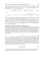
The simulator is busy working in two shifts to teach and keep up the knowledge of the
operating personnel of the NPP. It is very difficult to obtain simulator time for other
purposes. The most expensive part of the training simulator is the Control room and the
corresponding real-time I/O interface to it. Replacing the Control room with a couple of
high resolution touch-screens we will be able to reproduce it in several copies, that way to
make it affordable for different studies and planned refurbishments, and for teaching
students and non-operative personnel, too. Having multiple copies definitely increases the
quality of service and support to the operation of our nuclear power plant, producing close
to 40% of electricity of our country.
Nuclear Power - System Simulations and Operation
20
7. Acknowledgment
I would like to explain my gratitude to my dear colleagues; the advice and help of them
during the last 30 years was indispensable to achieve our goals. Special thanks to Laura
Bürger, Endre Vegh (both already retired), to Katalin B. Szabó, Dr. Gábor Házi and József
Páles for their permanent support. On the international scene I can thank a lot for the
valuable support and encouragement of Prof. Dr. Richard Zobel (now retired) and Prof.
Agostino Buzzone.
All of the works described above could not be successfully accomplished without the
brilliant knowledge and grateful assistance of the instructors and other personnel of the
Paks full-scope replica simulator. The help and cooperation of György Nagy, László Dercze,
Sándor Borbély, Sándor Czekmeister, József Göttli and others was essential to achieve these
results.
8. References
Anthony Ralston: A First Course in Numerical Analysis. Published by McGraw Hill Inc.,
1965. Hungarian translation: Műszaki Könyvkiadó, 1969.
Gábor Házi, Gusztáv Mayer, István Farkas, Péter Makovi and A. A. El-Kafas: "Simulation of
a small loss of coolant accident by using RETINA V1.0D code", Annals of Nuclear
Energy, Volume 28, Issue 16, November 2001, Pages 1583-1594
István Farkas, Gábor Házi, Gusztáv Mayer, András Keresztúri, György Hegyi and István
Panka, “First experience with a six-loop nodalisation of a VVER-440 using a new
coupled neutronic-thermohydraulics system KIKO3D-RETINA V1.1D” Annals of
Nuclear Energy, Volume 29, Issue 18, December 2002, Pages 2235-2242
Janos Sebestyen Janosy: Modeling and Simulation of Nuclear Energy in Eastern Europe.
Business and Industry Simulation Symposium, 2003 Advanced Simulation Technologies
Conference, Orlando, Florida, March 30 - April 03, 2003, ISBN 1 56555 263 6
A. Keresztúri, Gy. Hegyi, Cs. Maráczy, I. Panka, M. Telbisz, I. Trosztel and Cs. Hegedűs,
Development and validation of the three-dimensional dynamic code - KIKO3D,
Annals of Nuclear Energy Volume 30 (2003) pp. 93-120.
Janos Sebestyen Janosy: Simulation Aided Instrumentation and Control System
Refurbishment at Paks Nuclear Power Plant. First Asian International Conference on
Modeling and Simulation, AMS 2007, 27-30 March 2007, Phuket, Thailand,
ISBN 0 7695 2845 7
Janos Sebestyen Janosy: Simulators and Simulation used in Nuclear Power Plant Related
Projects. Keynote speech, CUTSE 2007 Curtin University of Sarawak Engineering
Conference, 26-27 November, 2007, Miri, Sarawak, Malaysia.
Janos Sebestyen Janosy: Simulators are the key for large-scale Instrumentation and Control
System Refurbishment Projects. Keynote speech, Second Asian International Conference
on Modeling and Simulation, AMS 2008, May 12-15, 2008, Kuala Lumpur, Malaysia.
2
Safety Studies and General Simulations of
Research Reactors Using Nuclear Codes
Antonella L. Costa
1
, Patrícia A. L. Reis
1
,
Clarysson A. M. Silva
1
, Claubia Pereira
1
, Maria Auxiliadora F. Veloso
1
,
Bruno T. Guerra
1
, Humberto V. Soares
1
and Amir Z. Mesquita
2
Departamento de Engenharia Nuclear – Escola de Engenharia
Universidade Federal de Minas Gerais
Instituto Nacional de Ciências e Tecnologia de Reatores Nucleares Inovadores/CNPq
2
Centro de Desenvolvimento da Tecnologia Nuclear/Comissão Nacional de Energia
Nuclear – CDTN/CNEN
Brasil
1. Introduction
Interest in safety issues of nuclear research reactors is nowadays increasing due their
enlarged commercial exploitation commonly directed at neutrons generation for several
types of scientific and social purposes. Power generation is not the main activity of a nuclear
research reactor reaching maximum power operation of about 100 MW. In spite of this,
specific features are necessary to ensure safe utilization of such installations. Therefore,
several codes have been used focusing special attention for research reactors safety analysis
and valuation of specific perturbation plant processes. A combination of codes for thermal
hydraulic analysis, for assessment of probabilistic risk, fuel investigation and reactor physics
studies are fundamental tools for an appropriate reactor behaviour definition.
It is appropriate to use internationally recognized, accepted and validated best estimate
codes. The continuous development and validation of the nuclear codes ensures the
improvement of best estimate methods. Typically, thermal hydraulic system codes may
need the most effort in terms of developing input models for system analyses in research
reactors. The fuel codes can be used for analysis of design basis accident conditions and may
be used to provide initial conditions for the system thermal hydraulic codes. Neutron kinetic
codes can be coupled to thermal hydraulic system codes to provide a more realistic
simulation of transients where there is a large reactivity variation. Reactor physics codes are
typically used to support the performance of the core as well as to provide results used in
the system thermal hydraulic codes for accident analysis. Containment codes may be
necessary to estimate parameters as the time of failure of the containment, confinement or
reactor building.
In this Chapter, the state-of-the-art related to nuclear codes applied to research reactors are
being presented. Results of simulations performed with two specific codes, the thermal
hydraulic RELAP5 code and the General Monte Carlo N-Particle Transport code (MCNP),
for the TRIGA IPR-R1 research reactor in Brazil are also presented.
Nuclear Power - System Simulations and Operation
22
2. Nuclear research reactors in operation
The main activity of the nuclear research reactors is not connected to power generation.
However, they are widely used to several activities as to non-destructive materials testing,
radioisotopes production, nuclear medicine, research, and many others fields.
The Research Reactor Database (RRDB) of the International Atomic Energy Agency (IAEA)
contains administrative, technical and utilization information on over 670 research reactors
including critical and sub-critical assemblies in 69 countries and the European Union.
Second the RRDB data, nowadays there are 239 research reactors in operation around the
world (see Table 1). Approximately, half of this total is now over 40 years old being
necessary to address deficiencies and new requirements that evolve over time. In this way,
reactor organizations undertake an array of work activities to either re-establish performance
that has degraded over time, maintain performance in the face of changing conditions or
adapt to new customer or regulatory demands (IAEA, 2009).
Status Developed Countries Developing Countries
Cancelled 1 4
Operational 148 91
Shut down 183 21
Decommissioned 194 16
Temporary shutdown 8 5
Planned 1 1
Under construction 2 1
Unverified information 0 1
Total 537 140
From IAEA (2011)
Table 1. Research reactors in the world
The operating mode as well as the design of research reactors can vary largely differently
from the power reactors. The most common design of research reactors is the pool type,
where the core is a cluster of fuel elements sitting in a large pool of water. The water in the
pool has function of cooling, as well as moderation, neutron reflector and it is able to assure
an adequate radioactive shielding. The reactor cooling occurs predominantly by natural
convection, with the circulation forces governed by the water density differences. The heat
generated from the nuclear fissions can be also removed pumping the pool water through a
heat exchanger characterizing a forced cooling.
Some examples of different types of research reactors are listed in Table 2. The TRIGA
reactor is the most common design having about 60-100 cylindrical fuel elements with metal
cladding enclosing a mixture of uranium fuel and zirconium hydride. The main
characteristic of this type of fuel is the prompt negative temperature coefficient that
provides safety and automatically limiting the power when excess of reactivity is suddenly
inserted. Fig. 1 shows a photography of an upper view of the research reactor type open-
pool IPR-R1 TRIGA. IPR-R1 is installed at Nuclear Energy Development Centre (CDTN) of
Brazilian Nuclear Energy Commission (CNEN), in Belo Horizonte, Brazil. It works at 100
kW but will be briefly licensed to operate at 250 kW. It presents low power, low pressure,
for application in research, training and radioisotopes production. The reactor is housed in a
6.625 meters deep pool with 1.92 meters of internal diameter and filled with light water.
Safety Studies and General Simulations of Research Reactors Using Nuclear Codes
23
Other research reactor designs are moderated using heavy water or graphite. The fast
reactors are in a small number; they require no moderator and can use a mixture of uranium
and plutonium as fuel. Homogenous type reactors have a core comprising a solution of
uranium salts as a liquid, contained in a tank about 300 mm diameter. This type was
popular in the past due to its simple design; however only a small number is nowadays in
operation. High temperature research reactors, as that developed in Japan (the HTTR – High
Temperature Test Reactor), have mainly the aim of to investigate the TRISO fuel designed
for the Generation IV power reactors, as the HTGRs - High Temperature Gas Reactors -
Verfondern et al., 2007).
Fig. 1. Core upper view and pool of the IPR-R1 TRIGA
Graphite or beryllium is commonly used as the reflector in research reactors, although other
materials may also be used. The fuel of research reactors can be of type HEU (highly
enriched uranium) or LEU (low enriched uranium). However, because of the programmes
of nuclear non-proliferation, there is a tendency of the countries to convert core reactor HEU
to LEU.
The fuel assemblies of research reactors are typically made in plates or cylinders, as
presented in the examples of Figure 2 and Figure 3, respectively. Figure 2 illustrates the
MTR (material testing reactor) fuel assembly used in the IEA-R1. A typical IEA-R1 fuel
element has 18 plane parallel fuel plates, mounted mechanically between two lateral
aluminium holders with grooves, and its overall dimensions are (7.6 X 8.0) cm and 88.0 cm
high. Each fuel plate consists of an aluminium cladding and a meat where the nuclear fuel is
located (Terremoto et al., 2000).
Nuclear Power - System Simulations and Operation
24
Figure 3 presents the design of two types of cylindrical fuel elements used in the research
reactor IPR-R1. This fuel contains high concentrations of hydrogen using a metal alloy of
uranium and zirconium and its main characteristic is the prompt negative temperature
coefficient.
Type Name Country
Power
(kW)
Criticality
Thermal Flux
(n/cm²s)
Fuel and
Enrichment
TRIGA IPR-R1 Brazil 100 1960 4.3 x 10
12
U-Zr-H
20%
Pool IEA-R1 Brazil 5000 1957 4.6 x 10
13
U
3
O
8
-Al and
U
3
Si
2
-Al
20%
Pool MTR MNR Canada 5000 1959 1.0 x 10
14
U
3
Si
2
-Al
19.75%
Fast Source TAPIRO Italy 5 1971
(Fast Flux) 4.0
x 10
12
U-Mo alloy
93.5%
High Tem-
perature Gas
HTTR Japan 30000 1998 7.5 x 10
13
UO
2
6%
Argonaut UFTR USA 100 1959 2.0 x 10
12
U
3
Si
2
-Al
19.75%
Heavy Water NBSR USA 20000 1967 4.0 x 10
14
U
3
O
8
-Al
93%
From IAEA (2011)
Table 2. Examples of nuclear research reactors
Fig. 2. Cross-sectional diagram of a standard MTR fuel element irradiated in the IEA-R1
research reactor, showing in detail the structure of two successive fuel plates (measure in
cm). Adapted from (Terremoto et al., 2000)
Safety Studies and General Simulations of Research Reactors Using Nuclear Codes
25
Fig. 3. IPR-R1 TRIGA – design of two types of cylindrical fuel elements (measure in mm)
3. Application of nuclear codes in research reactor analysis
In general, the codes used for research reactors analysis are also used in the nuclear power
plant (NPP) having both the same basis of development and utilization. The differences on
validation and application for each case appear due the complexity of the different classes of
reactors. Particularly, the codes available internationally for safety analysis of research
reactors can be classified in different issues according with their application including
reactor physics, fuel behaviour, thermal hydraulic processing, computational fluid
dynamics (CFD) and structural analysis (IAEA, 2008). Each of these topics are being
explained with some more details and exemplified next.
Nuclear Power - System Simulations and Operation
26
3.1 Neutron kinetic modeling
Reactor physics codes are capable to model the 2D or 3D core neutron kinetics for analysing
local or asymmetrical effects in the reactor core that is possible to occur as in steady state as
in transient operation. Examples of reactor physics codes are WIMS-D, DYN3D, CITATION,
PARET and NESTLE. WIMS-D, a deterministic code system for reactor lattice calculation,
can be used to calculate group constants dividing the core into several identical unit cells.
The calculated cross-sections can then be used as input to another type of code as, for
example, the code CITATION for global core calculations (Khana et al., 2000; Dalle et al.,
2002).
The computer code DYN3D was developed for safety analyses of nuclear reactors after
reactivity perturbations of the system, but it can be used also for fuel management
calculations.
PARET code has been used extensively for research reactor analysis which iteratively solves
for the neutronic-hydrodynamic-heat transfer aspect of the reactor under steady state and
transient behaviour. It can be used to investigate core reactivity insertions being a coupled
kinetics and thermal hydraulics code for predicting the course of non-destructive transients
in research reactors (Woodruff et al., 1996; Housiadas, 2002; Velit and Primm, 2008).
Other example is the NESTLE code that solves the two or four group neutron diffusion
equations in either Cartesian or hexagonal geometry using the Nodal Expansion Method
(NEM) and the non-linear iteration technique. NESTLE was embedded in the thermal
hydraulic code RELAP5 obtaining the multi-dimensional neutron kinetics model RELAP5-
3D. Steady-state eigenvalue and time dependent neutron flux problems can be solved by the
NESTLE code as implemented in RELAP5-3D. In spite of RELAP5-3D to be developed for
power reactors applications, it has been successfully used for research reactors analyses
(Costa et al., 2011; Marcum et al., 2010).
Therefore, as can be verified from some before examples, generally two or more codes are
used directly or indirectly connected for a more detailed and realistic simulation exploring
the main capability of each one.
Calculations using discrete ordinate diffusion and transport theory have been used
extensively for reactor simulation purposes. However, the Monte Carlo technique offers
significant advantages, since the complex geometrical configuration of the reactor core can
be modelled in detail. Therefore, the Monte Carlo code (MCNP) has been applied to
research reactor simulations mainly for neutron flux calculations (Fernandes et al., 2010;
Shoushtari et al., 2009; Stamatelatos et al., 2007; Huda, 2006). A more detailed example of the
MCNP code application to simulations of neutron flux value on the irradiation channels of
the IPR-R1 TRIGA research reactor, adapted from (Guerra et al., 2011), has been presented
in the Annex A.
3.2 Fuel analysis
Researchers in several countries have worked with the aiming to develop codes that predict
the behaviour of a fuel assembly during extreme transients as, for example, a LOCA (loss of
coolant accident). Such codes attempt to predict the deformation of a fuel rod, the
termination of deformation by rupture, the temperature reached by the cladding, oxidation
of cladding, and in some codes, the interaction between neighbouring rods. Codes which
calculate fuel rod behaviour in whole assemblies including rod-to-rod interactions are
relatively rare. One example of such code is the Japanese FRETA-B specialised in two-
dimensional analysis in the transverse direction (NEA, 2009). DRACCAR is other example
Safety Studies and General Simulations of Research Reactors Using Nuclear Codes
27
of fuel code that is currently under development at IRSN (Institute for Radiological
Protection and Nuclear Safety) with the purpose of to simulate the thermal mechanical
behaviour of a rod bundle under LOCA with a 3D multi-rod description (Papin et al., 2006).
3.3 Thermal hydraulic modeling
Thermal hydraulic system codes are applicable to a wide variety of reactor designs and
conditions. Such system codes allow simulating the complete primary and secondary
circuits and the interactions between them. Examples of system thermal hydraulic codes are
RELAP5, TRAC, CATHARE, ATHELET, DINAMIKA and CATHENA. They are generally
classified as best estimate codes. The term “best estimate code” means that the code is free of
deliberate pessimism and contains sufficiently detailed models to describe the relevant
processes of the transients that the code is designed to model (IAEA, 2008).
Models for two fluid, non-equilibrium hydrodynamics, point and multidimensional reactor
kinetics, control systems, and special system components make these thermal hydraulic
codes very attractive. However, the use of these codes for research reactors must be careful
in order to ensure that the models included in such codes are valid for the operating regimes
of the research reactors. The validity of the models and correlations should be verified.
As an example, the ATHLET thermal hydraulic code developed at the GRS, Society for Plant
and Reactor Safety, was planed to analyse leaks and transients for power reactors. However,
to extend the applicability of the code to the safety analysis of research reactors, a model
was implemented permitting a description of the thermal-dynamic non-equilibrium effects
in the subcooled boiling regime (Hainoun et al., 1996).
In the same way, the RELAP5 code has been modified to better simulate the research
reactors operation conditions (low pressure, low mass flow rate, low power). For example, a
subcooled boiling model of upward vertical flow consistent with phenomenological
observations of the subcooled flow boiling mechanisms was proposed to extend the range of
applicability of the RELAP5 code to low pressures (Končar and Mavko, 2003). Therefore,
recent works as, for example (Antariksawan et al., 2005; Khedr et al., 2005; Marcum et al.,
2010; Reis et al., 2010), have been performed to investigate the applicability of the RELAP5
code to research reactors operating conditions (TRIGA 2000, MTR, Oregon State TRIGA,
IPR-R1 TRIGA), respectively. Application of a model for the IPR-R1 TRIGA using the
RELAP5 code is detailed in the Annex B.
The user of a thermal hydraulic system code has a very large number of available basic
elements (single volumes, pipes, branches, junctions, heat structures, pumps, etc) to develop
a detailed reactor nodalization. The model can reproduce a specific part or the whole system
to be simulated. However as there is not a fixed rule to perform the nodalization, a large
responsibility is passed to the user of the code in order to develop an adequate model
scheme which makes best use of the various modules and the prediction capabilities of the
specific code (Petruzzi and D’Auria, 2008; D’Auria and Galassi, 1998).
Subchannel codes are used to analyse specific processes within the core of the reactor, such
as localized flow and heat transfer variables in representative fuel assemblies. Examples are
PARET and COBRA codes.
Computational Fluid Dynamics (CFD) is increasingly being used in the nuclear community
to model safety relevant phenomena occurring in the reactor coolant system and for the
analysis of localized phenomena such as the flow pattern in complex geometries. However,
CFD is a relatively recent development and their qualification status for application in
transient flow analysis for research reactor licensing should be verified.
Nuclear Power - System Simulations and Operation
28
3.4 Structural codes
Structural analysis codes are used to describe the behaviour of mechanical components such
as core support and pool structures, in the case of a pool type reactor, under various accident
conditions. These codes are commercially available and have generally been developed for
non-nuclear applications. They utilize boundary conditions supplied, for example, by
thermal hydraulic codes. Examples of structural analysis codes are NASTRAN and ANSYS.
NASTRAN, the NASA Structural Analysis System, is a powerful general purpose finite
element analysis program and it is a standard in the structural analysis field, providing the
engineer with a wide range of modelling and analysis capabilities. The computational
programme ANSYS is a multipurpose finite element code that can perform a variety of
calculations, including stress analysis, temperature distributions, and thermal expansions in
solid materials.
4. Verification and validation of codes
The applicability of a code to reactor safety analysis, mainly for licensing, is directly related
with its qualification which must be rigorously documented. It is not possible to provide a
detailed list of the key phenomena and code features necessary for each type of code.
However, the IAEA proposes basically three criteria to verify the adequacy of the codes for
treating important phenomena (IAEA, 2008):
a. The use of internationally recognized and accepted codes provides some assurance that
the codes are adequate for their intended application.
b. Individual codes need to be evaluated on a systematic basis, comparing the intended
application of the code with the actual conditions for which the code is applied.
c. Lists of important phenomena expected during the transients that constitute the target
of the investigation must be established. In many cases, documentation is available on
an individual code basis that describes the relative importance of the different
phenomena.
Code verification is defined as the review of the source coding against its description in the
documentation. The line by line verification of large codes is a time consuming and
expensive process. Therefore, this process is limited to only some codes. However, many
industry sponsored codes have been subjected to stringent verification procedures as a
consequence of the regulatory licensing process (IAEA, 2008).
Extensive code validation requires efforts at the international level, involving validation
projects, usually managed by the code developers and carried out, under cooperation and
exchange agreements, by user groups worldwide with access to experimental facilities
designed to provide data on behaviour and phenomena of importance. Several international
standard problems provide comparison between codes.
The validation of a code modelling for determined system implicates that the model
reproduces the measured steady-state conditions of the system with acceptable margins.
The nodalization may be considered qualified when it has a geometric fidelity with the
system, it reproduces the measured steady-state condition of the system, and it
demonstrates satisfactory time evolution conditions (D’Auria et al., 1999). However,
sometimes a nodalization qualified to simulate determined condition may not be suitable to
simulate other type of situation being necessary modifications and re-qualification.
Sensitivity analysis including systematic variations in code input variables or modelling
parameters, must be used to help identify the important parameters necessary for an
accident analysis by ranking the influence of accident phenomena or to bound the overall
Safety Studies and General Simulations of Research Reactors Using Nuclear Codes
29
results of the analysis. Results of experiments can also be used to identify important
parameters (Reis et al., 2011).
5. Safety analysis criteria
The acceptance criteria are essential to classify the results obtained from a safety analysis
and they may be specified as basic and specific. Basic acceptance criteria are usually defined
as limits set by a regulatory body. The specific acceptance criteria are used to include
additional margins beyond the basic acceptance criteria to allow for uncertainties and to
provide additional defence in depth. The margin between results predicted by the analysis
and the acceptance criterion is related to the uncertainties. If a result has low uncertainty, a
small margin to the acceptance criteria may be acceptable. In general, the adequacy of the
margin with the acceptance criterion is demonstrated by using a conservative analysis to
meet the acceptance criterion (IAEA, 2008).
Deterministic techniques are the main tools used in the analyses of research reactors. These
techniques are often related with the conservatism, commonly knew as conservative
approach. On the other hand, best estimate method provides a realistic simulation of a
physical process to a level commensurate with the currently known data and knowledge of
the phenomena concerned. A best estimate analysis must be supplemented by an
uncertainty analysis. Application of best-estimate (realistic) computer codes to the safety
analysis of nuclear plants implies the evaluation of uncertainties. This is connected with the
(imperfect) nature of the codes and of the process of codes application. The source of
uncertainties affects the predictions by best-estimate codes and must be taken into account
(D’Auria, 2004).
6. Reactor parameters in the safety analysis
The safety analyses are used in several areas including design, licensing, support for
accident management and emergency planning. Reactor parameters and some operating
conditions considered in the safety analysis can be summarized in: state of the reactor
operation, core power, core inlet temperature, fuel element cladding temperature; system
pressure, core flow, axial and radial power distribution and hot channel factor; reactor
kinetics parameters, fuel and moderator temperature reactivity coefficients, void reactivity
coefficient, available shutdown reactivity worth and insertion characteristics of reactivity
control and safety devices.
The evaluation of the safety of research reactors includes firstly the determination of the
reactor response to a range of postulated initiating events (PIEs) covering all supposed
possible types of events. Several selected PIEs for research reactors have been classified and
summarized as follows (IAEA, 2005):
a. Loss of electric power supplies;
b. Insertion of excess reactivity;
c. Loss of flow;
d. Loss of coolant;
e. Erroneous handling or failure of equipment;
f. Special internal events;
g. External events;
h. Human errors.
Nuclear Power - System Simulations and Operation
30
The PIEs in each group should be evaluated to identify the events that would be limiting,
and from there the events selected for further analysis should be indicated. Such events
would include those having potential consequences that bound all other PIEs in the group.
For example, to TRIGA reactors, due the passive nature of the reactivity feedback during a
temperature excursion, few PIEs would be applied since any increase in core temperature
has a negative reactivity effect, causing a passive reduction in reactor power to limit a
temperature excursion reactor. In spite of this, some perturbation situation may occur
disturbing the normal reactor operation, as a condition of forced recirculation off. The
event can be caused by the recirculation pump failure e can be classified inside the event
number 3 described before. Annex B presents an example of simulation of this event using
a TRIGA model in the RELAP5 code with results very approximate from the experimental
data.
7. Conclusion
This Chapter has drawn the attention to specific features related to the safe utilization of
research reactors. A summarized state-of-the-art about research reactors was presented.
As it was illustrated, the rising interest in the commercial exploitation of these types of
nuclear reactors is justified by the several applications using mainly their neutrons
generation. Due the considerable age of the majority of research reactors in operation
around the world, it is necessary to address deficiencies and new requirements that evolve
over time. Works have been performed with the aim of either re-establish performance that
has degraded over time, maintain performance in the face of changing conditions or adapt
to new customer or regulatory demands. As part of these efforts, several codes have been
used focusing special attention for the research reactors safety analysis including thermal
hydraulic analysis, fuel investigation, reactor physics and structural studies. Codes
internationally recognized, accepted and validated are essential in reactor safety analysis
that are used in several areas including design, licensing, support for accident management
and emergency planning.
An important aspect in the applicability of a code to reactor safety analysis is its direct
relation with its qualification which must be rigorously documented. Moreover aspects
connected to the validation, uncertainty analysis and sensitivity analysis must be carefully
considered for a correct application of a nuclear code for the simulation of reactor model.
Examples of application of two types of codes widely used for research reactors analysis are
being presented in the Annex A and B (MCNP and RELAP5 codes, respectively). These
Annexes present results of simulations performed at the Nuclear Engineering Department
of the Federal University of Minas Gerais for the TRIGA IPR-R1 research reactor in Brazil.
8. Acknowledgment
The authors would like to thank to Nuclear Technology Development Centre/Brazilian
Nuclear Energy Commission (Centro de Desenvolvimento da Tecnologia Nuclear/Comissão
Nacional de Energia Nuclear - CDTN/CNEN), Research Support Foundation of the State of
Minas Gerais (Fundação de Amparto à Pesquisa de Minas Gerais - FAPEMIG), Brazilian
Council for Scientific and Technological Development (Conselho Nacional de
Desenvolvimento Científico e Tecnológico - CNPq) and the Coordination for the
Improvement of Higher Education Personnel (Coordenação de Aperfeiçoamento de Pessoal
de Nível Superior - CAPES) for the support.
Safety Studies and General Simulations of Research Reactors Using Nuclear Codes
31
ANNEX A. Example of MCNP code application to IPR-R1 research reactor
The Annex A and also the Annex B are based in the IPR-R1 research reactor and they are a
summary of the works (Guerra et al., 2011) and (Reis et al., 2010), respectively.
AI. Introduction
The IPR-R1 is a reactor type TRIGA, Mark-I model that is installed at Nuclear Technology
Development Centre (CDTN) of Brazilian Nuclear Energy Commission (CNEN), in Belo
Horizonte, Brazil. It is a light water moderated and cooled, graphite-reflected, open-pool
type research reactor. IPR-R1 works at 100 kW but it will be briefly licensed to operate at 250
kW. It presents low power, low pressure, for application in research, training and
radioisotopes production. The fuel is an alloy of zirconium hydride and uranium enriched
at 20% in
235
U.
The IPR-R1 reactor has a Rotary Specimen Rack, RSR, outside the reactor, and it is
composed by forty irradiation channels in a cylindrical geometry. Moreover, tangent to
annular reflector, there is a Pneumatic Tube where the samples also can be inserted to
irradiation. Therefore, the IPR-R1 has three facilities for sample irradiation: the Central
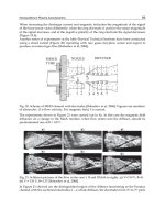
Thimble, the Rotary Specimen Rack and the Pneumatic Tube. Figure A1 shows the radial
and axial core configuration. The IPR-R1 has the main nuclear applications related with
neutron activation analysis (NAA), training of operators for nuclear power plants and
experiments in neutronic and thermal hydraulic.
Fig. A1. Core upper view and pool of the IPR-R1 TRIGA
Nuclear Power - System Simulations and Operation
32
The IPR-R1 has been simulated using the code MCNPX2.6.0 (Monte Carlo N-Particle
Transport eXtend). The goal was to evaluate the neutronic flux in a sample inserted in the
RSR channels. In each simulation the sample was placed in a different position, totalling
forty positions around the RSR. The results obtained from the calculation show good
agreement in relation to experimental data.
AII. Modelling
The reactor model was developed using MCNP5 and MCNPX codes where 500 active cycles
were calculated with 1000 neutrons per cycle. The simulations executed in MCNPX code,
considers 1.0 hour of irradiation (time of sample irradiation) with 0.1 MW (currently TRIGA
reactor power). The simulated model was based on previous studies where the reactor core
has the same features of the IPR-R1 geometry described before. The configured geometry is
the same to MCNP5 and the MCNPX 2.6.0. The core was configured considering a cylinder
containing water, fuel elements, radial reflectors, central tube (or central thimble), control
rods and neutron source. Each rod has a coordinate value. They were filled according to
their individual characteristics. Around the core there is the RSR which has groove to insert
the samples to irradiation. The configured core is inside the pool where water surrounds the
core and the RSR. However, the model of this work presents some improvements.
Table A1 presents the cylinders dimensions which are inside of RSR. In addition, Figure A2
illustrates the axial and radial view of the simulated model.
Cylinder Material Inner Radius (cm) Radial Thickness (cm) Height (cm)
Aluminum 1.50 0.10 20.0
Polystyrene 1.10 0.30 7.90
Polyethylene 0.48 0.07 0.55
Table A1. Dimensions of the simulated cylinders inside Rotary Specimen Rack
Fig. A2. Axial and radial view of the reactor TRIGA IPR-R1 simulated in MCNP5 and
MCNPX codes
Safety Studies and General Simulations of Research Reactors Using Nuclear Codes
33
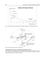
AIII. Results and conclusions
The assembly of the three cylinders was positioned in 40 different positions of the RSR to
calculate the thermal neutron flux (energies of 0.5 eV or smaller) inside of the polyethylene
cylinder that contains the sample. The Figure A3 shows the thermal neutron flux simulated
by MCNP5 and MCNPX codes. It is possible to see clearly the behaviour of the thermal
neutron flux around the core reactor. The neutron fluxes vary at each position and changes
over the RSR. In spite of the good agreement of the most of the calculated points some
differences were observed. These differences must be justified by a theoretical analysis and
using a statistical program.
Fig. A3. Axial and radial view of the reactor TRIGA IPR-R1 simulated in MCNP5 and
MCNPX codes
Although the neutron flux value was calculated in 40 positions in the RSR, the reference
work presents only 11 experimental data. Table A2 presents the values of thermal neutron
flux calculated by the codes MCNP-4B, MCNP5 and MCNPX 2.6.0. The results are being
compared with experimental data and the error is presented in percentage.
Eight positions present differences smaller than 10% and three positions present differences
smaller than 21%. In this way, it is possible to conclude that the most of the calculated
results are in good agreement with the experimental measurements.
The results showed that there is good agreement between the experimental data and the
values calculated by the used codes. The errors presented by the most of estimated flux are
smaller than 10% and three positions presented differences between 10 and 21%. The tool
employed by MCNP5 and MCNPX 2.6.0 estimate the flux average inside of the cylinder
which contains the sample. However, the used codes have other method to calculate the
neutron flux as Forced Collision, Point Detectors, Spherical Detector, etc. These tools may
improve the results decreasing the differences between experimental data and the calculated
values. For more details of this work see (Guerra et al., 2011).