Nuclear Power System Simulations and Operation Part 12 ppt
Bạn đang xem bản rút gọn của tài liệu. Xem và tải ngay bản đầy đủ của tài liệu tại đây (453.52 KB, 15 trang )
Nuclear Power - System Simulations and Operation
154
into different load sets and using different design criteria and requirements, the safety
degree consideration and the occurrence probability of a given load can be introduced in the
design evaluation.
In accordance with ASME III, non-linear design evaluation is an alternative to the linear design
evaluation. Depending on which stress intensity limit is violated in the linear design
evaluation, there are two types of non-linear analysis required in ASME III for the
alternative non-linear design evaluations: (1) collapse-load analysis and (2) non-linear
transient analysis. For clarity, such alternative design criteria and requirements which are
specified in connection with such non-linear analyses are termed hereby as the non-linear
design criteria and requirements. Such non-linear finite element analyses can generally
effectively be conducted using general-purpose finite element software, such as ANSYS
(ANSYS, 2010) and most other well recognized software.
This Chapter is devoted to describe the general procedure for the alternative non-linear
piping design and to clarify those relevant non-linear design criteria and requirements. Our
emphasis will be placed on the later task as unclear and inconsistent issues have been
observed in ASME III when non-linear design criteria and requirements applied. In recent
years, quite many non-linear analyses and design evaluations have been conducted in
Sweden for several power uprate projects. Unfortunately, most of such work has always
ended with, or can never be ended without, long discussions on such unclear and
inconsistent issues.
The Chapter is organized as follows: In Section 2, an overview on loading conditions is
given. In Section 3, we review the linear design evaluation and discuss the non-linear design
evaluation for Class 1 piping systems. In Section 4, the review and discussion are continued
for Class 2 and 3 piping. In Section 5, we briefly address the computational procedures for
collapse-load analysis and, in Section 6, we discuss the computational procedures for non-
linear transient analysis. Finally, in Section 7 concluding remarks are given. We note that the
discussion given in this Chapter is mainly based on our experiences on the application of
ASME III under Nordic conditions, see e.g. Zeng (2007), Zeng & Jansson (2008), Zeng et al.
(2009, 2010).
As this chapter covers a large amount of design rules and requirements of ASME III, an
attempt has been made to keep the presentation brief and concise, yet still sufficiently clear.
Unless otherwise stated, notations will be kept to be identical to those used in ASME III,
equations specified in ASME III will not be repeated here unless necessary, and
fundamental design requirements e.g. Pressure Design etc., will not be discussed here. In
particular, the description of the linear design evaluation will be kept brief whenever possible
and, for a more detailed description, we refer to ASME (2009), Slagis & Kitz (1986), Slagis
(1987) and references therein.
2. Load conditions
The design evaluation rules in ASME III are for Class 1, 2 and 3 piping specified in terms of
5 loading conditions: Design Condition, and Service limits of Level A, B, C and D.
Under each loading condition, loads are combined to one or several load set(s) according to
Design Specifications. The rules for load-combinations are defined in accordance with
probabilities in which corresponding loads (events) should occur and consequences that
may result in. Thus, a given load set defines the following:
Non-Linear Design Evaluation of Class 1-3 Nuclear Power Piping
155
1. Loads and their combinations to be considered in piping analysis.
2. Stress intensity limits to be used in the subsequent design evaluation.
In Tab. 1 we show an example of how these load sets are specified in Sweden. The design
evaluation must be conducted in accordance with this table and the piping design is not
qualified unless all evaluation rules specified for each load set are met.
We note that in Tab. 1 notations are of self-explaining, e.g. PD for Design Pressure and SSE
for Safe-Shutdown Earthquake etc. Rather than explaining how load-combinations are
defined in Tab. 1, which is not our purpose, we should observe the followings from this
table:
1. Loads given under Design Condition are not only static loads of Design Pressure (PD)
and Dead Weight (DW), but also dynamic loads (GV/SRV1) which represents here
those generated by opening or closing one safety valve.
2. Loads in Service limit Level A include static loads (PO+DW) and dynamic loads
GV/SRV1, where PO denotes the operating temperature. We note that GV/SRV1 are
generally not included according to ASME III, and they appear here due to additional
requirements specified in Swedish design specifications.
3. Loads in Service limit Level B include static loads (PO+DW), time-dependent loads
generated by opening or closing of seven safety valves (GV/SRV7).
4. Loads in Service limits of Level C and D include static loads (PO+DW), dynamic loads
generated by e.g. opening or closing of several safety valves, and Safe-Shutdown
Earthquake (SSE) and so forth.
Tab. 1 is only an example for our discussion purpose. In practice, more load cases and
combinations need to be considered, such as Water-Hammer loads (WH), local vibration
due to safety relief of valves, Local vibration due to chugging, Pool swell drag due to
internal pipe break, Pool swell impact due to internal pipe break and several others.
Load-combinations Design and/or
Service limit Level
Pressure Temp.
PD + DW Design PD TD
PD + DW + GV/SRV1* Design PD TD
PO + DW + GV/SRV1* Level A PO TO
PO + DW + GV/SRV7 (E-3) Level B PO TO
PO + DW + SRSS(GV/SRV7(E-2), WH/VO1) Level C PO TO
PO + DW + SRSS(GV/SRV7(E-3), GV/SSE)
Level D PO TO
Table 1. Load-combinations and their evaluation specifications
It should be noticed that time-dependent loads can be either given in form of response
spectra, which are the case when GV/SSE and GV/SRV or other global vibration (GV)
related events considered, or in form of time-dependent “nodal forces” F(t) which are in
most cases generated in separate fluid dynamic analyses.
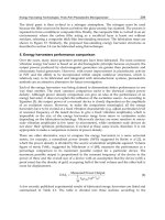
Time-dependent loads F(t) can be reversing, non-reversing or non-reversing followed by
reversing, see NB-3620, NC-3620 (ASME, 2009a). In Fig.1 we show an example of non-
reversing followed by reversing F(t) caused typically by an initial water slug followed by
Nuclear Power - System Simulations and Operation
156
reflected pressure pulses. As we will see later, some design rules, in particular, those non-
linear ones are given in terms of the types of dynamic loads. When dealing with dynamic
loads, it is therefore important to distinguish reversing and non-reversing types.
Non-reversing load
Mean load
F(t) (N)
Time (s)
T
1
Fig. 1. Dynamic loading of a non-reversing type followed by a reversing type
3. Class 1 piping
The linear design rules for Class 1 piping are given in NB-3600 for general rules and in NB-
3650 – NB-3656 for specific rules. When the linear design rules unsatisfied, in other words,
the piping design found to be disqualified, the piping can still be qualified if alternative non-
linear design requirements specified generally in NB-3200 Design by Analysis, where
material plasticity are treated in NB-3228, can be met. In this section, we follow the rules
specified in NB-3600 for each specific load set to clarify these non-linear design requirements.
In ASME III, different design requirements are, in general, specified in terms of two types of
loads: (1) Loads including non-reversing dynamic loads or non-reversing followed by
reversing dynamic loads; (2) Loads including reversing dynamic loads. The definitions for
reversing and non-reversing dynamic loads are given in NB-3622 and repeated below:
Reversing dynamic loads are those loads which cycle about a mean value and include
building filtered loads, earthquake, and reflected waves in piping due to flow transients
resulting from sudden opening/closure of valves. A reversing load shall be treated as non-
reversing when the following condition is met: The number of reversing dynamic cycles,
excluding earthquake, exceeds 20.
Non-reversing dynamic loads are those which do not cycle around a mean value, and
include initial thrust forces due to sudden opening/closure of valves and water-hammer
resulting from entrapped water in two-phase flow.
3.1 Design condition
The linear design evaluation for this load set is to evaluate Eq.(9) given in NB-3652 to ensure
the primary (primary membrane plus primary bending) stress intensity is within its limit
1.5S
m
, where S
m
is the allowable design stress intensity value. According to NB-3228.1 or
NB-3228.3, the non-linear design requirements can be formulated as follows: If Eq.(9)
Non-Linear Design Evaluation of Class 1-3 Nuclear Power Piping
157
unsatisfied, a non-linear analysis can be made to predict the collapse-load and the design
can still be considered to be qualified if the applied loads do not exceed 2/3 of the collapse-
load. The collapse-load may be predicted either by a Limit Analysis procedure specified in
NB-3228.1 or a Plastic Analysis procedure specified in NB-3228.3.
There is a fundamental difference between these two procedures. While the Limit Analysis
procedure aims at predicting the lower bound of the collapse-load, the Plastic Analysis
procedure implies a prediction of the whole load-displacement history until the structure
reaches, or passes through, its collapse point. The prediction of the collapse-load will be
elaborated in Sect. 5.
In addition to this fundamental difference, NB-3228 requires the following:
For the Limit Analysis, the material is assumed to be perfectly elastic-plastic, and the yield
stress is set to 1.5S
m
. The yield stress can be reduced for some materials, see NB-3228.1. A
von Mises yield criterion is used. The lower bound of the collapse-load can be computed
incrementally or by other available procedures. Here, the historic behavior in the piping
during the loading process, such as plastic strains, is of no interest.
The Plastic Analysis requires that the true material stress-strain relation, including strain
hardening behavior, should be used. A von Mises yield condition is still assumed and the
initial yield stress must be set to the true yield stress S
y
. The collapse-load can only be
computed by an incremental procedure and it can only be determined when (almost) the
whole historic behavior in the piping during the whole loading process is computed.
Moreover, the collapse-load in this context is a load-level that is determined using a specific
procedure given in NB-3213.25, not the load-level corresponding to the collapse point
predicted numerically, see Section 5.
The Limit Analysis is simpler but predicts, however, the lower bound of the collapse-load. It
implies generally an application of a stronger evaluation requirement. Nevertheless, it is
reasonable to use the Limit Analysis as the first choice when Eq.(9) unsatisfied.
3.2 Level A
In the linear design evaluation for all load sets for which Service limit Level A is designated,
two types of requirements are to be satisfied: (a) fatigue requirements and (b) thermal
ratchet requirements, see NB-3653.
3.2.1 Fatigue evaluation
The fatigue requirements are specified in NB-3653.1 – 3653.6. In principle, the following two
conditions are verified:
1. Primary plus secondary stress intensity range.
The evaluation is done by using Eq.(10), NB-3653.1, to ensure the stress intensity range
S
n
≤3S
m
. The evaluation must be made for all load sets in Level A.
2. Peak stress intensity range.
The evaluation is done by using Eq.(11), NB-3653.2, to determine a so-called alternating
stress intensity S
alt
(NB-3653.3), which is in turn used to find the allowable number of
load cycles N in design fatigue curves (NB-3653.4). Thereafter, a procedure defined in
NB-3222.4(e)(5) is applied to estimate the cumulate damage (NB-3653.5). The design is
qualified if we find a so-called cumulative usage factor U≤1.0. This evaluation must be
made for all load sets in Level A.
Remark: These fatigue requirements (1) and (2) must also be verified for all load sets which
are designated in Service limit Level B, see Section 3.3. When computing the cumulative
Nuclear Power - System Simulations and Operation
158
usage factor U, all load-sets in Level A and all load sets in Level B must together be taken
into account.
Now we shall clarify what we can do if the fatigue requirements (1) and (2) cannot be
fulfilled. NB-3653.6 states that if Eq.(10) unsatisfied, one may apply a so-called simplified
elastic-plastic discontinuity analysis to evaluate Eqs. (12) and (13), and the cumulative damage
factor using a slightly modified procedure, NB-3653.6 (a), (b) and (c). The design is qualified
if Eqs.(12) and (13) satisfied, and U≤1.0.
At this point, one may ask: What can we do if Eq.(10) satisfied, but the cumulative damage
factor in Condition (2) found to be U>1.0? ASME NB is unclear on this point. One may
realize that, in the simplified elastic-plastic discontinuity analysis, the alternating stress
intensity is increased by a factor K
e
≥1.0 through Eq.(14), which in turn reduces the limit of
load-cycles, and consequently increases the cumulative damage factor U. In such cases, the
simplified elastic-plastic discontinuity analysis will not help in one’s attempt to further
verify the piping design.
NB-3653.1(b) states that, as an alternative to the simplified elastic-plastic discontinuity
analysis in NB-3653.6, one may apply a Simplified elastic-plastic analysis specified in NB-
3228.5. When discussing this issue, we must remark the following: NB-3600 provides design
rules/criteria for only piping. Whereas NB-3200 provides design rules/criteria which are
more general and detailed and applicable for all nuclear facility components including
piping. In other words, NB-3600 states simplified methods of NB-3200 for performing
design-by-analysis for piping. Hence, a piping component which fails to meet conditions in
NB-3600 can still be qualified if it meet conditions given in NB-3200. As far as piping
concerned, the design rules and requirements given in NB-3200 and NB-3600 should be the
same.
We look now back to Eq.(10). Recall that Eq.(10) ensures the primary plus secondary stress
intensity range being within its limit 3S
m.
By examining NB-3220 we find, however, that
none of rules given in NB-3228 seems to be directly applicable for doing a further evaluation
when U>1 found in a simplified elastic-plastic analysis. Furthermore, that NB-3200 does not
state any further design requirement if the peak stress intensity range leads to a cumulative
usage factor U>1.
Now, a question arises: Can we apply non-linear analyses to do a further design assessment
when Eq.(10), or Eqs.(12) and (13), unsatisfied and/or the cumulative usage factor found to
be U>1? In Section 3.2.3, we shall attempt to answer this question.
3.2.2 Thermal stress ratchet evaluation
The thermal stress ratchet evaluation is given in NB-3653.7 which ensures the range of
temperature changes, ΔT
1 range
, is within its limit. NB-3653.7 does not state any further
assessment rule if the range of temperature changes overshoots its limit. However, in NB-
3228.4 Shakedown Analysis, it is stated that a refined non-linear analysis, which will be
reviewed and discussed in detail in the next Section, can be used to further check if the
piping components can still be qualified.
3.2.3 Non-linear design evaluation
In NB-3228.4 Shakedown Analysis, both Thermal Stress Ratchet in Shell (NB-3222.5) and
Progressive Distortion of Non-integral Connections (NB-3227.3) are discussed. In NB-
3228.4(b), it is stated that the design can be considered to be acceptable provided that the
following two conditions satisfied:
Non-Linear Design Evaluation of Class 1-3 Nuclear Power Piping
159
1. The maximum accumulated local strain at any point, as a result of cyclic operation to
which plastic analysis applied, does not exceed 5%.
2. The deformations which occur are within specific limits.
These two conditions will, for convenience in the later discussion, be termed as the 5% strain
limit rule.
The 5% strain limit rule is according to NB-3228.4(b) a design requirement which replaces the
following specific requirements: (1) NB-3221.2 Local membrane stress intensity being less
than 1.5S
m
; (2) NB-3222.2 Primary plus secondary stress intensity range being less than 3S
m
,
i.e. Eq.(10) in NB-3653; (3) NB-3222.5 Thermal stress ratchet, and (4) NB-3227.3 Progressive
distortion (deformation) control. In other words, this rule sets a limit of progressive
deformation in a shakedown process that may eventually take place. We note that this rule
applies for both general piping components and non-integral connections (screwed on caps,
screwed in plugs, closures etc).
By thermal stress ratchet it is meant in NB-3222.5 an action, more exactly speaking, a
response, in that deformation caused during thermal cyclic loading increases by a nearly
equal amount in each cycle. The danger does not lie in the response (deformation) caused in
any particular load cycle, but the accumulated amount irreversible (plastic part) response,
which may lead to uncontrollable progressive distortion. This may explain why ASME III
limits the temperature range ΔT
1 range
in the linear design evaluation, but imposes the 5%
strain limit rule when plasticity considered. In all load sets of Service limit Level A, thermal
transients (TT) are of main concern. This implies that a shakedown process is irremissible
and the 5% strain limit rule becomes the right choice.
Now, we consider again the fatigue control or evaluation. Does this 5% strain limit rule cover
also the need for fatigue control? Generally speaking, it does not! Damage due to fatigue is a
totally different damage phenomenon than that caused by material (plastic) yielding. While
the former is mostly dominated by brittle failure in form of micro-fracture and cracking, the
later is entirely a ductile failure process in which the dislocation of material crystalline
grains is dominating. These two damage mechanisms must be dealt with separately.
To answer how a Class 1 piping under Service limit of Level A should be verified through a
non-linear analysis when the linear design evaluation found unsatisfied, the author suggests
the following:
1. If the thermal stress ratchet condition unsatisfied, the 5% strain limit rule can always be
applied.
2. If Eq.(10) unsatisfied, the simplified elastic-plastic discontinuity analysis should be the
first choice for further evaluation.
3. If Eqs.(12) and (13) unsatisfied, and U>1 (evaluated by the procedure given in NB-
3653.6), the 5% strain limit rule will be applied first. If this rule unsatisfied, the design
cannot be qualified (or must at least be further questioned)! If satisfied, we shall first
notify the owner of the nuclear power plant. If the owner requests a further evaluation,
a refined approach for calculating the cumulative factor U, which is based on the
numerical results from non-linear analyses, should be suggested to the contractors (and
the owner of the nuclear power). This should be handled on a base of individual cases.
If such an approach agreed, the evaluation goes further. Otherwise, the design is
declared to be disqualified.
One may argue that the simplified elastic-plastic analysis cannot help if U>1 predicted in
Step (2) above. The point is, when the simplified elastic-plastic analysis requested in
PIPESTRESS for fatigue evaluation, Eqs.(12), (13) and (14) will be evaluated together and, at
Nuclear Power - System Simulations and Operation
160
the same time, a updated cumulative factor U will be reported. We remind that, as discussed
earlier in Section 3.2.1, if Eq.(10) satisfied but U>1, this simplified elastic-plastic analysis
cannot alter the result U>1.
Furthermore, one may think that it may be possible that, one obtains the following results
from a linear analysis using e.g. PIPESTRESS: Eqs.(12) and (13) unsatisfied, but U≤1. This
situation should actually not happen as, according to NB-3653.6, Eqs.(12) and (13) should
first be satisfied before computing U.
3.3 Level B
The linear design evaluation for all load sets for which Service limit Level B is designated, is
the same as that for Service limit Level A, see NB-3654. The evaluation requirements are
basically given in terms of loads including non-reversing and reversing load types. We
notice that the formulation in NB-3654 is unclear with regard to fatigue requirements. More
specifically, the first paragraph in NB-3654 contradicts with NB-3654.2, stating whether all
load sets in Level A and B, or all load sets in Level A and (only) reversing loads in Level B,
should all together be considered when computing the cumulative damage factor in fatigue
evaluation. We agree the following:
a. To satisfy Eq.(9) in NB-3652 for non-reversing loads, or reversing loads combined with
non-reversing loads (NB-3654.2(a)).
b. To satisfy the fatigue requirements specified in NB-3653.1 through NB-3653.6 for both
reversing and non-reversing loads (NB- 3654.2(b)).
c. To satisfy the thermal ratchet requirement given in NB-3653.7 for all load sets including
thermal loads (NB-3654.2(b)).
3.3.1 Non-reversing dynamic loads
When Eq.(9) verified, the stress intensity limit is according to NB-3654.2 set to 1.8S
m
, but no
greater than 1.5S
y
. Recall that it sets to 1.5S
m
for Service limit Level A loads, implying a 20%
relaxation of the stress intensity limit for Level B loads as compared to that for Level A
loads.
Any direct instruction for further evaluation has not explicitly been given in NB-3654 and
NB-3223 if Eq.(9) unsatisfied. We note that the first statement in NB-3654 is “The procedures
for analysing Service Loadings for which Level B Service Limits are designated, are the same
as those given in NB-3653 for Level A Service Limits”. This should allow us, as we do for
Level A loads, to apply NB-3200 to use a non-linear analysis to predict the collapse-load, or
its lower bound, and the design can still be qualified if the applied loads are less than 2/3 of
the collapse-load. The remaining question is how various parameters, such as the yield
stress and so on, should be set in a non-linear analysis.
If the collapse-load is predicted in accordance with the Plastic Analysis specified in NB-
3228.3, there will be no ambiguity as the true material yield stress and true stress-strain
relation are used, see also Section 5.1. However, if a Limit Analysis is chosen, we may then
ask: Should the yield stress be set to 1.5S
m
as for Level A loads? Or should it be set to a
value corresponding to the stress intensity limit 1.8S
m
(but no greater than 1.5S
y
) that is used
in connection with the linear design evaluation?
The authors favor to set the yield stress to 1.8S
m
(but no greater than 1.5S
y
) based on the
following “engineering” reasoning: (1) Setting 1.5S
m
as the yield stress in a Limit Analysis for
Level A loads is because the stress intensity limit for Level A loads sets to 1.5S
m
, which
Non-Linear Design Evaluation of Class 1-3 Nuclear Power Piping
161
should be an important correlation between the linear and non-linear designs. (2)The linear
and non-linear design principles can differ in many ways, but they are set in order to
achieve, for an ideal design, the same safety margin. (3)The fact that the stress intensity limit
for Level B loads is 20% relaxed as compared to that for Level A loads in a linear design
should be “accounted or compensated” somewhere in its corresponding non-linear design,
through e.g. raising the yield stress by 20% or, equivalently the factor 2/3 to 1.2x2/3=4/5.
There are different views about the above choice in Sweden. Some colleagues advise that the
yield stress must set to 1.5S
m
in the Limit Analysis for all loads no matter which Service limits
they are designated to. We will return to this issue in Section 5.2.
Remark: All load sets in Level A and B (both reversing and non-reversing) must be together
taken into account when computing the cumulative usage factor U.
3.3.2 Reversing dynamic loads
The evaluation of the fatigue and thermal ratchet requirements are the same as those given
in Section 3.2. Additionally, it is required (NB-3654.1(b)) that any deflection limit prescribed
by the design specification must be met. Our suggestions for a non-linear evaluation are
described in Section 3.2.3.
Remark: All load sets in Level A and B (both reversing and non-reversing) must be together
taken into account when computing the cumulative usage factor U.
3.4 Level C
The linear design evaluation for all load sets for which Service limit Level C is designated, is
given in NB-3655. The evaluation rules are again given in terms of reversing and non-
reversing loads.
We note in advance that for Service limit Level C deformation limits prescribed by design
specifications are explicitly required to be verified, see NB-3653.3. This is required for loads
of both non-reversing and reversing types.
3.4.1 Non-reversing dynamic loads
For non-reversing loads, Eq.(9) in NB-3652 should be applied with a relaxed stress intensity
limit 2.25S
m
, but no greater than 1.8S
y
, which is relaxed by 25% as compared to Service limit
Level B.
If Eq.(9) unsatisfied, similarly to cases for Level B loads, any direct instruction for further
evaluation has not explicitly been given in NB-3655 and NB-3224.
Referring to our discussion in Section 3.3.1 for Level B loads, it should be reasonable to use
the same approach that handles Level B loads to do a further evaluation. That is, a non-
linear finite element analysis is used to predict the collapse-load or its lower bound. The
design can still be qualified if the applied loads are less than 2/3 of the collapse-load.
Again, if the collapse-load is predicted in accordance with the Plastic Analysis specified in
NB-3228.3, there will be no ambiguity as the true material yield stress and true stress-strain
relation are used. However, if a Limit Analysis is chosen, we may again ask: Should the yield
stress be set to 1.5S
m
as for Level A loads? Or should it be set to a value corresponding to the
stress intensity limit 2.25S
m
(but no greater than 1.8S
y
) that is used in connection with the
linear design evaluation?
The author favor again, based on the same reasoning given in Section 3.3.1, the choice of
setting the yield stress to 2.25S
m
(but no greater than 1.8S
y
) or, equivalently setting the yield
Nuclear Power - System Simulations and Operation
162
stress to 1.5S
m
but increasing the factor
2
3
to
2.25 2
1.0
1.5 3
×=
. There are different views on
such a choice. A few co-workers believe that the yield stress should always be set to 1.5S
m
in
a Limit Analysis for all loads no matter which Service limits they are designated to, see a
more in-depth discussion in Section 5.3.
3.4.2 Reversing dynamic loads
The evaluation rule for reversing loads is given in NB-3655.2(b). The evaluation is done by
applying conditions given in NB-3656(b), which are given for loads in Service limit Level D.
When applying these conditions, the stress intensity limit given in NB-3656(b)(2) remains
the same, and those given in NB-3656(b)(3,4) are reduced by 30%. The fatigue evaluation is
not required.
If the evaluation of NB-3656(b) disqualified, a further assessment can be done by applying
the 5% strain limit rule described in Section 3.2.3 without any modification. This follows from
the following reasoning:
1. When NB-3656(b) cannot be fulfilled, one checks further the conditions in NB-3656(c).
NB-3656(c) states that design rules in Appendix F can be used as an alternative to NB-
3656(a,b). One observes however that Appendix F is not specified for reversing loads.
2. Although no explicit rules found in Appendix F for reversing loads, one can fortunately
find in NB-3228.6 the following statements: “As an alternative to meeting the
requirements of Appendix F, for piping components subjected to reversing type dynamic
loading …, the requirements of (NB-3228.6) (a)(1) and (a)(2) below shall be satisfied”.
3. NB-3228.6(a)(2) concerns the fatigue control which is not required for Level C loads. This
means that only NB-3228.6(a)(1) needs to be followed.
4. NB-3228.6(a)(1) states that “The effective ratchet strain averaged through the wall
thickness of the piping component due to the application of all simultaneously applied
loading including pressure, the effect of gravity, thermal expansion ranges, earthquake
inertia ranges, anchor motion ranges, (including thermal, earthquake etc.) and reversing
dynamic loading ranges shall not exceed 5%”. (Notice the badly formulated texts!)
Remark: There are different views on the above reasoning as Appendix F is not given for
reversing loads. A few people argue that the only alternative to NB-3655.2 is the application
of NB-3224.7, which requires fulfilling the requirements of through NB-3224.1 to NB-3224.6.
It indicates in turn by NB-3224.7 that NB-3228 Plastic Analysis, with 70% of the specified
allowable strain values, can be applied. Namely, we require (i) the maximum accumulated
local strain being less than 0.7x5%=3.5%, and (ii)
10
0.7
a
an
S
EN
ε
≤⋅
, see Section 3.5.2.
3.5 Level D
The linear design evaluation for all load sets for which Service limit Level D is designated, is
done similarly to that specified for Service limit Level C, and the general evaluation rules
are given in NB-3656. The evaluation rules are again specified in terms of the two types of
loads as defined for Level B and C loads, i.e. non-reversing and reversing loads.
3.5.1 Non-reversing loads
For non-reversing loads, the linear evaluation rule is given in NB-3656 (a), which states that
Eq.(9) in NB-3652 should be applied with a relaxed stress intensity limit 3.0S
m
, but no
greater than 2.0S
y
.
Non-Linear Design Evaluation of Class 1-3 Nuclear Power Piping
163
If Eq.(9) unsatisfied, NB-3656(c) can be applied, which in turn refers to Appendix F,
indicating that a non-linear evaluation can be done through the prediction of the collapse-
load or its lower bound.
Appendix F states general rules and acceptance criteria for piping analyses when Service
limit Level D considered. Roughly speaking, the requirements specified for Service limit
Level D are relaxed as compared with Service limits of Level A, B and C. Below we shall
have a close look at Appendix F.
The general acceptance criteria when material plasticity taken into account are given in F-
1340. It is stated (F-1341) that the acceptability may be demonstrated using one of the
following methods: (a) Elastic analysis; (b) Plastic analysis; (c) Collapse-load analysis; (d)
Plastic instability analysis; and (e) Interaction methods. This is, in our opinion, obviously not
a consequent and clear statement.
First, the option (a) is no longer applicable when plasticity considered. Secondly, plasticity
instability is a phenomenon that may for some cases, depending on both structure itself and
applied load, not always occur and, for other cases, can definitively occur long before the
applied load reaches its collapse point. Nevertheless, with reference to this statement and
the evaluation rule for non-reversing loads in Service limit Level C, it should be a correct
choice that we apply the option (c) Collapse-load analysis and, meanwhile, check if any
plastic instability shall take place. We note these two options can be examined in one non-
linear analysis, see below.
F-1341.3 states in connection with the collapse-load analysis that: The applied static load, or
its equivalent, should not exceed 100% of the collapse-load, or 90% of the lower bound of
the collapse-load obtained in a limit analysis.
When the limit analysis used, the yield stress is according to F-1341.3 set to min(2.3S
m
,
0.7S
u
), where S
u
is the ultimate strength (A relaxation of about 2% as compared to Service
limit Level C). Notice here that a different relaxation is used when setting the yield stress as
compared to that used for the linear design evaluation, where the stress intensity limit is set
to 3.0S
m
, that is, a relaxation of about 33% as compared to Service limit Level C. Apparently,
the advice of setting the yield stress to 1.5S
m
is not appropriate here.
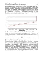
F-1341.4 states that “the applied load should not exceed 70% of the so-called plastic
instability load P
I
”. Generally speaking, P
I
can only be determined if an incremental
solution, with both material plasticity (true stress-strain relationship) and large deformation
taken into account, applied to numerically trace the response history. However, it is
generally not an easy task from numerical point of view, and requires finite element
software that are able to accurately handle various difficulties in so-called “path-searching”,
such as snap-back, snap-through and so forth, see Fig. 2, where local buckling or instability
appears, resulting a temporally and partly lost of the load-carrying capacity. Notice that if
thin-walled piping structures are under consideration, instability phenomena can in most
cases occur before the collapse-load reached, and P
I
can then be much less than the collapse-
load if there exist any material or geometric imperfection. Hence, it is equally important to
verify P
I
and the collapse-load. Unfortunately, it is often the case that plastic instabilities
cannot be accurately predicted and P
I
cannot be observed in numerical
results.
In Fig.2, two careless finite element (FE) solutions are shown. Both solutions fail to predict
the plastic instability phenomena. While the solution which diverged early leads to a much
conservative design, the other solution may result in a catastrophic design.
Fig. 2 also indicates that both the collapse-load and plastic instability load can be predicted
in the same non-linear analysis through tracing the responses history. This implies that a
Nuclear Power - System Simulations and Operation
164
collapse-load analysis should be the first choice. Whereas a limit analysis should be avoided
when the non-reversing loading considered and Eq.(9) in NB-3652 unsatisfied. Otherwise,
one cannot be sure if plastic instability is under control.
Force (N)
P
c
Collapse-load
Two careless FE -solutions
FE - solution diverged
P
I
Initial plastic instability
Displacement
(mm)
Fig. 2. Load-displacement relation including plastic instabilities typically observed in
structures of thin-walled members and two careless FE-solutions
3.5.2 Reversing dynamic loads
For the reversing loading, the linear design evaluation is done by evaluating conditions given
in NB-3656(b)(1)-(5). The fatigue evaluation is not required as for load sets in Service limit
Level D.
If the linear design evaluation disqualified, a further assessment can be done according to NB-
3228.6 (a)(1)-(2). The design is qualified if
1. the 5% strain limit rule is satisfied, NB-3228.6(a)(1); and
2. a thermal ratchet limit is satisfied through NB-3228.6(a)(2)
10a
an
S
EN
ε
≤
Above,
an
ε
is an effective cyclic single-amplitude strain,
10a
S
is the allowable fatigue stress
limit at 10 cycles according to the design fatigue curves given in ASME III Appendix I, and E
the Young’s modulus, N≥10 the number of cycles for general reversing dynamic loads
prescribed in design specifications, and N=10 for earthquake events.
For computing
an
ε
a procedure described in NB-3228.6(a)(2) should be applied. This
procedure requires operating at material-points of interest, e.g. element’s Gaussian points,
Non-Linear Design Evaluation of Class 1-3 Nuclear Power Piping
165
where the results of strain components are available, over a typical load cycle which is
considered to be of interest. Denote one chosen material-point by p and the procedure can be
summarized (in a standard tensor notation) as follows:
Step 1. Extract and record the strain results
k
i
j
ε
at all considered time-steps k=1,2, …, N in a
complete load cycle of interest.
Step 2. Calculate the strain change
k
i
j
ε
Δ
between each time-step k and a reference time-step
k
0
, e.g. k
0
=1. That is, for each
0
kk
≠
, we calculate
0
k
kk
ij ij
i
j
ε
εε
Δ= − .
Step 3. Calculate the (von Mises) equivalent strain change at time step
0
kk≠ , i.e.
2
3
kkk
e
q
i
j
i
j
ε
εε
Δ= ΔΔ.
Step 4. Find the maximum equivalent strain range by
max
max( ),
k
e
q
εε
=Δ 1,2, , .kN
=
Step 5. The effective cyclic single-amplitude strain is
max
1
2
an
εε
=
.
Notice that it is important to find the material-point at which the maximum equivalent
strain range takes place. Notice that software e.g. ANSYS does not directly provide such
output. Additional efforts must be made in order to evaluate this quantity.
4. Class 2 and 3 piping
The linear design evaluation rules for Class 2 are given in ASME III, NC-3652 – 3655 and
relevant rules are given in other items in NC-3600. The following discussion will first be
made by following the rules given in NC-3600. Thereafter, we describe alternative non-linear
design evaluation rules for Class 2 piping.
The rules for Class 3 piping (ND-3600) are basically the same as those for Class 2 piping
(NC-3600) and their difference is minor. They are, however, also applicable for Class 3
piping.
Similarly to Class 1 piping, different design requirements are, in general, specified for loads
including non-reversing dynamic loads or those including reversing dynamic loads.
4.1 Linear design evaluation
The linear design evaluation rules for all load sets in Design Condition, Service Limits of
Level A, B, C and D, are given in NC-3652 – 3655. These rules are summarized below. We
remark in advance that, except for Service limit Level D, no further design assessment
instruction has been provided if the linear design evaluation disqualified.
Design condition
For the Design Condition the effects of sustained loads should satisfy Eq.(8) in NC-3652 to
ensure the primary stress intensity within its limit 1.5S
h,
where S
h
is the basic material
allowable stress at design temperature. In addition, the moment term M
A
in Eq.(8) should be
given based on conditions according to NCA-2142.1(c) Design Mechanical Loads.
We note that for Class 1 piping the stress intensity limits are always defined in term of S
m
.
Notice the difference that for Class 2 the “hot” allowable stress S
h
is in use. This happens for
all load conditions, see below.
Nuclear Power - System Simulations and Operation
166
Level A and B
The design requirements for Levels A and B are given in a badly formulated text. In
particular, requirements given in NC-3653.2 are confusing and can be interpreted in several
ways. We agree the following interpretation:
For the Service limit Level B, the effects of sustained loads, occasional loads including non-
reversing dynamic loads should satisfy Eq.(9) in NC-3653.1 to ensure the primary stress
intensity within its limit 1.8S
h
.
For the Service limit of Levels A and B, the effects of thermal expansion should satisfy
Eq.(10), and the effects of any single non-repeated anchor movement Eq.(10a), see NC-
3653.2. As an alternative to the fulfilment of, Eq.(10), Eq.(11) shall be satisfied.
For the Service limit of Levels A and B, the effect of reversing loads must always meet the
condition given in Eq.(11a) in NC-3653.2(d).
Level C
For the Service limit Level C, the evaluation rules are also specified in terms the two types of
loads as defined for Class 1 piping, i.e. non-reversing and reversing loads.
The effects of the non-reversing loads should satisfy Eq.(9) with a relaxed stress intensity
limit 2.25S
h
(but no greater than 1.8S
y
).
For the reversing loads, conditions given in NC-3655(b) should be satisfied, using the
allowable stress in NC-3655(b)(2), and 70% of the allowable stresses in NC-3655(b)(3-4).
Furthermore, deformation limits given by design specifications should be verified.
Level D
For the Service limit Level D, the evaluation rules are again specified in terms of the two
types of loads as defined for Class 1 piping, i.e. non-reversing and reversing loads.
NC-3655(a) requires that the effects of the non-reversing loads should satisfy Eq.(9) with a
relaxed stress intensity limit 3.0S
h
(but no greater than 2.0S
y
). For the reversing loads,
conditions given in NC-3655(b) should be satisfied. NC-3655(c) states that “the rules given
in Appendix F, where non-linear design requirements are given, can be used as an
alternative to verify both non-reversing and reversing loads”.
4.2 Non-linear design evaluation
The review that we made in Section 4.1 indicates that, except for Level D, no further
evaluation instruction has been provided if the linear design evaluation disqualified. The
question becomes: For other load sets, can we apply non-linear analyses to further assess the
piping design as we do for Class 1 piping?
It has been discussed and argued that piping and vessels are similar, and one may apply
NC-3200 Alternative Design Rules for Vessels to do such job. Hence, evaluation rules given
in Appendix XIII, and in particular those given in Appendix XIII-1150 Plastic Analysis,
Limit Analysis and Shakedown Analysis, can directly be used as advised in NC-3221.1.
We note that there is one major difference between design rules for Class 2 vessels (NC-
3300) and piping (NC-3600), see e.g. Slagis (1987). Vessels are required to meet stress limits
on “primary” stresses only. Whereas for piping, thermal expansion stresses including
concentration effects are explicitly evaluated against relevant limits through Eqs.(10-11), see
NC-3653.2, which is a control on fatigue. From this point of view, it is not appropriate to
apply NC-3200 Alternative Design Rules for Vessels for Class 2/3 piping.
Non-Linear Design Evaluation of Class 1-3 Nuclear Power Piping
167
4.2.1 A Class-upgrade alternative
When Level D considered, the application of Appendix F to verify a Class 2 piping in cases
when the linear design evaluation disqualified is, in fact, equivalent to consider the Class 2
piping as Class 1. This can be straightforward realized by carefully examining how a Class 1
piping is verified for Level D, see Section 3.5. This observation is, to the authors’ point of
view, important as it implies two design principles for Level D when material plasticity
taken into account:
1.
The Class 2 piping is considered as a Class 1 piping.
2.
The design requirements specified for Class 1 in accordance with the considered load
set, without any modification/relaxation, are applied.
One may naturally ask why these principles are only applied to Level D, but not to all load
sets. There are different guesses/explanations and attempts to justify them. To find the
answer is not the scope of this report. We note only that the load sets in Level D includes
loads resulted from the most extreme accidents e.g. the lost of coolant, leading generally to
(large amount) plastic deformations, which implies consequently that the linear design
evaluation that is purely based on stress limits becomes for some cases too easy to be
violated, and can no longer play an appropriate role as a criterion to justify the acceptability
of the piping design.
Our experiences have indicated that design evaluation for Class 2 piping with material
plasticity taken into account for all other load sets has been of a great concern and become a
natural request. Under the circumstances that no clear rules have been given for load sets of
Design Condition and Levels A, B and C, we think it should be a reasonable alternative to
apply the above two principles. One may argue that such an alternative is conservative and
possible involves partly unnecessary work. To compromise these, we think it should be
reasonable to partly introduce a “relaxation” in the second principle above.
4.2.2 More on the Class-upgrade alternative
The difference between the Class-upgraded alternative, discussed in the previous section,
and the argued alternative discussed in Section 4.2.1, needs possibly to be further clarified.
These two treatments are fundamentally different. To apply NC-3200 Alternative Design
Rules for Vessels for Class 2/3 piping does not have a principal support. They are made for
vessels and there are, as discussed earlier, differences between vessels and piping.
However, to raise a Class 2/3 piping to Class 1 does not fundamentally change the type of a
structure, but only strengthens the design requirements or design safety considerations. The
strengthened design safety will be loosen or, speaking in more appropriate words, balanced
through relaxing those individual Class 1 design requirements. There may be many ways to
relax those requirements and will, in some cases, have to find an “engineering” compromise
between requirements for Class 1 and 2/3. The relaxation needs to be done on a base of
concrete “individual case” and engineering judgments, which should be documented in
detail. We believe that it coincides with the general design principles that ASME III has
built.
5. Collapse-load analysis
As we discussed in Ch. 3 and 4, an alternative to the fulfilment of Eq.(9) in NB-3652 for Class
1 piping (Design, Level B, C and D), and of Eq.(9) in NC-3653 for Class 2/3 piping (Level D),
is to apply a non-linear finite element analysis to predict the collapse-load, and to ensure
Nuclear Power - System Simulations and Operation
168
that the applied load does not exceed a certain percentage of the collapse load. We shall here
discuss such a non-linear evaluation in a more detailed setting.
One must first realize that a collapse-load analysis deals only with cases when applied loads
are static, such as PD+DW and PO+DW+D/B shown in Tab. 1. We remember, however, that
ASME III suggests that it may also be applied for cases where non-reversing dynamic loads
are involved. We notice that a direct application of a collapse-load analysis when dynamic
loads involved is not possible. In the following, we shall first focus us on cases with static
loads.
Load P
P
c
Collapse - Load
C
P
ca
D
Φ
e
B
()
ec
Φ=Φ
−
tan2tan
1
A
Response/Displacement (d)
“
Collapse- point” according to ASME III (II-1430)
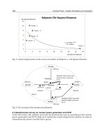
Fig. 3. Load-response history and the collapse-load
5.1 General
When plasticity and/or geometric non-linearities taken into account, a structure will loose
its load-carrying capacity when the applied load P reaches a critical level, or collapse-load,
P
c
. To determine the collapse-load, it is required to numerically predict the load-response
history, see e.g. Fig. 3 for the simplest cases, from an early stage A until the collapse point C
and, in many cases, until a stage D far after the collapse point. The numerical prediction of a
load-response history in connection with finite element analysis is not a simple task as
pointed out in Section 3.5.1 and relevant publications (Jansson, 1995). For a comprehensive
discussion of corresponding computational procedures and numerical difficulties, we refer
texts e.g. Bathe (1996) and Crisfield (1996). We remark the following:
1.
At the collapse point the so-called tangent stiffness matrix is singular, implying usually
a divergence of solution or computation. However, a diverged solution or computation
does not necessarily imply that the collapse point has been reached or passed through.
The divergence can be resulted by instability as mentioned in Section 3.5.1 or many
other reasons.