Nuclear Power Operation Safety and Environment Part 6 docx
Bạn đang xem bản rút gọn của tài liệu. Xem và tải ngay bản đầy đủ của tài liệu tại đây (3.19 MB, 30 trang )
Investigation of High Energy Arcing Fault Events in Nuclear Power Plants
139
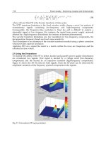
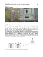
Fig. 1. Scheme of the electric circuit affected
Fig. 2. Cross section of the cable tray inside the cable cylinder blocks inside ground between
the buildings
Nuclear Power – Operation, Safety and Environment
140
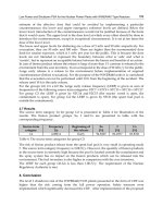
Fig. 3. Photos of the cable damage; left: location of the damaged cable, right: damage by the
cable fire/evaporation
Fig. 4. Cables with protection by intumescent coating; left: photo of the cable channel, right:
photo of the coating
Unfortunately, the pressure value having really occurred during the event could not been
determined. Damage to fire doors, dampers, or fire stop seals were not observed. The high
energy short circuit did not result in any fire propagation; the combustion was limited to the
location where the short circuit occurred. The fire self-extinguished directly after the electric
current had been switched off. The fire duration was only a few seconds, however, the
smoke release was high.
It has to be mentioned that all cables inside the cable channel were protected by intumescent
coating (see Figure 4 above). This coating ensured the prevention of fire spreading on the
cables.
The detailed analysis led to the definite result that the event was mainly caused by ageing of
the 10 kV cables. The ageing process was accelerated by the insufficient heat release inside
the cable cylinder blocks.
As a corrective action, all high voltage (mainly 10 kV) cables with PVC shielding being older
than 30 years were replaced by new ones.
Another effect of the event was the smoke propagation to an adjacent cable channels via a
drainage sump. As a preventive measure, after the event each cable channel was supplied
Investigation of High Energy Arcing Fault Events in Nuclear Power Plants
141
by its own drainage system. Moreover, all the channels were separated by fire barriers with
a resistance rating of 90 min.
5.2 Arcing fault in an electrical cabinet of the exciter system of an emergency diesel
generator
This event occurred at a German nuclear power plant in 1987.
Fig. 5. Photographs: a) view into the exciter cabinet, in the foreground location where the
screw loosened and b) view into the cabinet
Fig. 6. Photographs of the damaged fire door from outside the room
Nuclear Power – Operation, Safety and Environment
142
Performing a load test during a regular in-service inspection (usually at an interval of four
weeks) of the emergency diesel generator, an arcing fault with a short-to-ground took place
in the electrical cabinet of the exciter system of the emergency diesel generator (cf. Figure 5
above).
The ground fault is assumed to be caused by a loose screw. The ionization of air by the arc
developed to a short circuit within approximately four seconds.
The coupler breakers between the emergency power bus bar and the auxiliary bus bar
opened 0.1 s after the occurrence of the short circuit, due to the signal “overload during
parallel operation”.
1.5 s later the diesel generator breaker opened due to the signal "voltage < min” at the
emergency power bus bar. Another 0.5 s later the emergency power bus bar was connected
automatically to the offsite power bus bar.
The smouldering fire is believed to be caused by the short circuit of the emergency diesel
generator.
Due to the high energy electric arcing fault a sudden pressure rise occurred in the room
(room dimensions are approximately 3.6 m x 5.5 m x 5 m) that damaged the double-winged
fire door.
Photographs of the damaged fire door from outside the room are shown in Figure 6 above.
5.3 Short circuit leading to a transformer fire
This event occurred at a German nuclear power plant in June 2007. A short circuit resulted
in a fire in one of the two main transformers. The short circuit was recognized by the
differential protection of the main transformer. Due to this, the circuit breaker between the
380 kV grid connection and the affected generator transformer (AC01) as well as the 27 kV
generator circuit breaker of the unaffected transformer (AC02) were opened.
At the same time, de-excitation of the generator was actuated. The short circuit was thereby
isolated. In addition, two of the four station service supply bus bars (3BC and 4BD) were
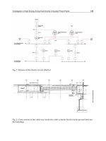
switched to the 110 kV standby grid (VE). A simplified diagram is given in Figure 7 (Berg &
Fritze, 2011).
Within 0.5 s, the generator protection system (initiating 'generator distance relay' by
remaining current during de-excitation of the generator which still feeds the shot circuit)
caused the second circuit breaker between the 380 kV grid connection and the intact
generator transformer (AC02) to open. Subsequently the two other station service supply
bus bars (2BB and 1BA) were also switched to the standby grid. After approx. 1.7 s, station
service supply was re-established by the standby grid.
Due to the short low voltage signalization on station service supply bus bars the reactor
protection system triggered a reactor trip.
As soon as the switch to the standby grid had taken place , feed water pump 2 was started
automatically. After about 4 s the pump stopped injecting into the reactor pressure vessel
and subsequently was switched off again. This caused the coolant level in the reactor
pressure vessel to drop so that after about 10 min the reactor protection system actuated
steam line isolation as well as the start-up of the reactor core isolation cooling system. About
4 min after the actuation of steam line isolation, two safety and relief valves were opened
manually for about 4 min. This caused the pressure in the reactor to drop from 65 bar to
approx 20 bar. As a result of the flow of steam into the pressure suppression pool, the
coolant level in the reactor pressure vessel dropped further.
Investigation of High Energy Arcing Fault Events in Nuclear Power Plants
143
Fig. 7. Simplified diagram of the station service supply and the grid connection of the
nuclear power plant
After closing the safety and relief valves the level of reactor coolant decreased further
because of the collapse of steam bubbles inside the reactor pressure vessel. Thereby the limit
for starting the high-pressure coolant injection system with 50 % feed rate was reached and
the system was started up by the reactor protection system. Subsequently, the coolant level
in the reactor pressure vessel increases to 14.07 m within 6 min. The reactor core isolation
cooling system was then automatically switched off, followed by the automatic switch-over
of the high-pressure coolant injection system to minimum flow operation. Subsequent
reactor pressure vessel feeding was carried out by means of the control rod flushing water
and the seal water.
Due to the damage caused by the fire in the transformer, the plant was shut down. The fire
of the transformer showed the normal behaviour of a big oil-filled transformer housing, the
fire lacks combustion air and produces a large amount of smoke (see Figure 8).
A detailed root cause analysis regarding the different deviations from the expected event
sequence was carried out. The cause of the fire was a short circuit in the windings of the
generator transformer. Due to the damages to the transformer it was not possible to resolve
the failure mechanisms in all details.
To end the short circuit, the differential protection system of the generator transformer
caused to open the circuit breaker between the 380 kV grid connection and the affected
generator transformer as well as the generator circuit breaker to the unaffected
transformer.
The generator circuit breaker to the affected transformer did not open since the generator
circuit breakers are not able to interrupt the currents flowing during a short circuit. The
10,5 kV ~
10,5 kV ~
G
BT 12
AQ 01
AT 01
4 BD
BT 01
3 BC
SP01
BT 02
2 BB
AT 02
AQ 02
1 BA
BT 11
27 kV ~
27 kV ~
27 kV ~
27 kV ~
U2 U1
110 kV~ Fremdnetz VE
400 kV~ KSA VE
AC 01 AC 02
10,5 kV ~
10,5 kV ~
G
BT 12
AQ 01
AT 01
4 BD
BT 01
3 BC
SP01
BT 02
2 BB
AT 02
AQ 02
1 BA
BT 11
27 kV ~
27 kV ~
27 kV ~
27 kV ~
U2 U1
110 kV~ Fremdnetz VE
400 kV~ KSA VE
AC 01 AC 02
G
BT 12
AQ 01
AT 01
4 BD
BT 01
3 BC
SP01
BT 02
2 BB
AT 02
AQ 02
1 BA
BT 11
27 kV ~
27 kV ~
27 kV ~
27 kV ~
U2 U1
110 kV~ Fremdnetz VE
400 kV~ KSA VE
AC 01 AC 02
Nuclear Power – Operation, Safety and Environment
144
opening of the circuit breaker between the second 380 kV grid connection and the
remaining intact generator transformer is caused by the remaining current after de-
exciting the generator which initiates the distance relay of the generator protection
system.
The loss of the operational feed water supply was caused by the time margins in between
the opening of the two 380 kV circuit breakers. The logical sequence in the re-starting
program of the feed water pumps could not cope with the specific situation of the delayed
low voltage signals during the incident.
The further drop in the reactor pressure vessel level following the actuation of steam line
isolation and the reactor core isolation cooling system was caused by the manual opening of
the two safety and relief valves for 4 min. The manual opening of safety and relief valves
was not needed in the case of this event sequence and at that point in time. The reason for
the manual opening of two safety and relief valves will be part of a detailed human factor
analysis which is not completed.
As a consequence of these indications, improvements concerning the fire protection of
transformers are intended in Germany (Berg et al., 2010).
Fig. 8. Flame and smoke occurring at the generator transformer; the photo on the right hand
shows the fire extinguishing activities
5.4 Phase-to-phase electrical fault in an electrical bus duct
A phase-to-phase electrical fault, that lasted four to eight seconds, occurred in a 12 kV
electrical bus duct at the Diablo Canyon nuclear power plant in May 2000 (Brown et al.,
2009). This bus supplied the reactor coolant and water circulating pumps, thus resulting in a
turbine trip and consequently in a reactor trip.
The fault in the 12 kV bus occurred below a separate 4 kV bus from the start-up transformer,
and smoke resulting from the HEAF caused an additional failure.
When the circuit breaker tripped, there was a loss of power to all 4 kV vital and non-vital
buses and a 480 V power supply to a switchyard control building, which caused a loss of
power to the charger for the switchyard batteries. After 33 hours, plant personnel were able
to energize the 4 kV and 480 V non-vital buses.
This event was initiated due to the centre bus overheating causing the polyvinyl chloride
(PVC) insulation to smoke, which lead to a failure of the adjacent bus insulation. Having
only a thin layer of silver plating on the electrodes, noticeably flaking off in areas not
directly affected by the arc, contributed to the high-energetic arcing fault event.
Investigation of High Energy Arcing Fault Events in Nuclear Power Plants
145
Other factors that caused the failure were heavy bus loading and splice joint configurations,
torque relaxation, and undetected damage from a 1995 transformer explosion. Two photos
of this failure are shown in Figure 9. More photos are provided in (Brown et al, 2009).
Fig. 9. Photographs of the damages at the Diablo Canyon nuclear power plant (from Brown
et al., 2009)
5.5 Short circuit due to fall of a crane onto cable trays
This event occurs at a Ukrainian plant which was at that time under construction when
work on dismounting of the lifting crane was fulfilled (IAEA, 2004).
The crane was located near the 330/6 kV emergency auxiliary transformers TP4 and TP5
which are designed for transformation 330 kV voltage to 6 kV for power supply of the 6kV
AC house distribution system of the unit 4 and the emergency power supply system 6 kV
for unit 3. They are located outside at a distance 50 m from the turbine hall of the unit 4.
There are two metal clad switchgear rooms (with 26 cabinets and 8 switchers) about four
meters from the emergency auxiliary transformers.
The supply of the sub-distribution buses building from the power centre rooms (see Figure
10), was ensured by a trestle with cable trays consisting of power, control and
instrumentation cables for the units 3 and 4.
All trays were provided with the cut-off fire barriers. The transformer rooms were supplied
by an automatic fire extinguishing system, which actuated when the gas and differential
protection actuated.
The event started when the jib of the crane fell on the trestle with the cables passed from
330/6 kV transformer TP 4 and TP 5 to unit 4 and broke them. The cables fell on the ground.
The diagram of the situation after the event is provided in Figure 10 (IAEA, 2004).
Damages of all cable trays lead to loss of instrumentation cables for relay protection of the
transformers and the trunk line 6 kV.
As a result the earth fault of the cables 6kV could not be disconnected rapidly. The
emergency relay protection of the transformers during earth fault 6 kV from the side 330 kV
with the executive current from the storage buttery for open-type distribution substation 330
kV was not designed.
To remove this earth fault the plant was cut off from outside high-voltage transmission lines
330 kV by electrical protection actuation and the voltage on the power supply bus was
decreased.
Nuclear Power – Operation, Safety and Environment
146
There was a loss of normal and emergency auxiliary power supply which resulted in a
decrease of the frequency of ´the power supply buses of the main coolant pumps. The
emergency protection was actuated and the reactors of units 2 and 3 were scrammed.
The long-term exposure of this earth fault (1 min and 36´sec.) caused a high earth fault
currents which burn the cables. This lead to a fire spread to the 6 kV supply distribution
buses and 6 kV metal clad switchgear rooms resulting inside these rooms in high
temperature and release of the toxic substance. Also the equipment of the transformers TP 4
and TP 5 was damaged.
Fig. 10. Diagram of the situation after the event (from IAEA, 2004)
The earth fault has to be disconnected with differential protection of the line 330 kV but it
was actuated with the output relays of the TP 4 and TP 5 which was damaged.
The fire was detected by the security guard, the on-site fire brigade was informed, including
the outside agency. The automatic fire extinguishing system was activated but stopped
working right away because of fire pump’s power supply loss. There was no water in the
fire mains.
Then the fire brigade laid fire-fighting hoses and provided water with a mobile pump unit.
Then the fire brigade waited for the permission from the shift leader.
In compliance with a written procedure, after elimination of the short circuit and restoration
of the house distribution power supply the fire brigades could start fire fighting and
extinguished the fire about one hour and thirty minutes after detection.
5.6 A triple-pole short circuit at the grounding switch caused by an electrician
In December 1975, a safety significant fire occurred in unit 1 of a nuclear power plant in the
former Eastern Germany (see, e.g., Röwekamp & Liemersdorf, 1993 and NEA, 2000) . At that
time, two units were under operation. Unit 1 was a PWR of the VVER-440-V230 type. The
reactor had 6 loops and 2 turbine generators of 220 MWe each.
An electrician caused a triple-pole short-circuit at the grounding switch between one of the
exits of the stand-by transformer and the 6 kV bus bar of the 6 kV back-up distribution that
Investigation of High Energy Arcing Fault Events in Nuclear Power Plants
147
was not required during power operation. The circuit-breaker on the 220 kV side was
defective at that time. Therefore, a short circuit current occurred for about 7.5 minutes until
the circuit-breaker was actuated manually. The over current heated the 6 kV cable which
caught fire over a long stretch in the main cable duct in the turbine building.
The reactor building is connected to the turbine building via an intermediate building, as
typical in the VVER plants. The 6 kV distribution is located in this building and the main
feed water and emergency feed water pumps all are located in the adjacent turbine building.
In the main cable routes nearly all types of cables for power supply, instrumentation and
control were located near each other without any spatial separations or fire resistant
coatings. In the cable route that caught fire there were, e.g., control cables of the three diesel
generators.
Due to the fire in the 6 kV cable, most of those cables failed. The cable failures caused a trip
of the main coolant pumps leading to a reactor scram and the unavailability of all feed water
and emergency feed water pumps. The heat removal from the reactor was only possible via
the secondary side by steam release. Due to the total loss of feed water, the temperature and
pressure in the primary circuit increased until the pressuriser safety valves opened. This
heating was slow, about 5 h, due to the large water volumes of the six steam generators, 45
m
3
in each. In this situation one of the pressuriser safety valves was stuck open. Then the
primary pressure decreased and a medium pressure level was obtained so that it was
possible to feed the reactor by boron injection pumps. Due to cable faults, the
instrumentation for the primary circuit was defective (temperature, pressuriser level). Only
one emergency diesel could be started due to the burned control cables. The primary circuit
could be filled up again with the aid of this one emergency diesel and one of six big boron
injection pumps. With this extraordinary method it was possible to ensure the residual heat
removal for hours.
The Soviet construction team personnel incidentally at the site then installed temporarily a
cable leading to unit 2. With this cable one of the emergency feed water pumps could be
started and it was possible to fill the steam generator secondary side to cool down the
primary circuit to cold shutdown conditions. Fortunately, no core damages occurred.
Regarding the weak points with respect to fire safety, first of all, the cause for the fire has to
be mentioned. This fire could only occur because there was no selective fusing of power
cables.
Another very important reason for the wide fire spreading concerning all kinds of cables
was the cable installation. Nearly all cables for the emergency power supply of the different
redundancies as well as auxiliary cables were installed in the same cable duct, some of them
on the same cable tray.
All the fire barriers were not efficient because the ignition was not locally limited but there
were several locations of fire along the cable.
In the common turbine building for the units 1 to 4 of the Greifswald plant with its total
length of about 1.000 m there were no fire detectors nor automatic fire fighting systems
installed. Therefore, the stationary fire fighting system which could only be actuated
manually was not efficient. The design as well as the capacity of the fire fighting system
were not sufficient.
Although there were enough well trained fire fighting people, the fire-brigade had problems
with manual fire fighting due to the high smoke density as there were no possibilities for an
efficient smoke removal in the turbine hall.
Nuclear Power – Operation, Safety and Environment
148
5.7 Explosion in a switchgear room due to a failure of a circuit breaker
In December 1996, in a PWR in Belgium the following event occurred. The operator starts a
circulating pump (used for cooling of a condenser with river water). This is the first start-up
of the pump since the unit was shut down.
About eight seconds later, an explosion occurs in a non safety related circuit breaker room
(located two floors below the control room), followed by a limited fire in the PVC control
cables inside the cubicles. Due to some delay in the reaction time of the protection relays,
normal (380 kV) and auxiliary (150 kV) power supply of train 1 are made unavailable. Safety
related equipment of train 1 are supplied by the diesel generating set 1. Normal power
supply of train 2 is still available.
The internal emergency plan is activated and the internal fire brigade is constituted. The fire
is rapidly extinguished by the internal fire brigade.
As a direct consequence of the explosion five people were injured during the accident, one
of them died ten days later.
The fire door at the room entrance was open at the moment of the explosion; this door opens
on a small hall giving access to the stairs and to other rooms (containing safety and non
safety related supply boards) at the same level; all the fire doors of these rooms were closed
at the moment of the explosion and were burst in by the explosion blast. Three other fire
doors were damaged (one of these is located on the lower floor); some smoke exhaust
dampers did not open due to the explosion (direct destruction of the dampers, bending of
the actuating mechanism). One wall collapsed, another one was displaced.
The explosion did not destroy the cubicle of the circulating pump circuit breaker; the supply
board and the bus bar were not damaged, except for the effects of the small fire on the
control cables; other supply boards located in the same room were not damaged. In the
room situated in front of the room where the explosion occurred, the fire door felt down on
a safety related supply board, causing slight damages to one cubicle (but this supply board
remained available except for the voltage measurement).
A comprehensive root cause analysis has been performed and has shown that the explosion
occurred due to the failure of the circuit breaker. The failure occurred probably when the
protection relay was spuriously actuated 0.12 seconds after the start up of the pump (over
current protection) and led to an inadvertently opening of the circuit.
Based on an investigation of the failing circuit breaker, it was concluded that two phases of a
low oil content 6 kV circuit breaker did not open correctly and the next upstream protection
device did not interrupt the faulting device. This has led to the formation of long duration
high energy arcing faults inside the housing and to the production of intense heat release.
This resulted in an overpressure with subsequent opening of the relief valve located at the
upper part of the circuit breaker presumably introducing ionised gases and dispersed oil
into the air of the cubicle/room. This mixture in combination with the arcs is supposed to be
at the origin of the explosion. Indications of arcing between the three phases of the circuit
breaker have been observed, resulting in a breach of the housing on two phases. Many
investigations were conducted to identify the root cause of the circuit breaker failure
(dielectric oil analyses, normal and penalising conditions tests, mechanical control
valuations) but no clear explanation could be found. Moreover, the circuit breaker
maintenance procedure was compared with the constructor recommendations and the
practice in France. No significant difference was noticed.
Although the explosion occurred in a non safety related supply boards room, the event was
of general importance, because the same types of circuit breakers were also installed in
Investigation of High Energy Arcing Fault Events in Nuclear Power Plants
149
safety related areas. Therefore, this event was reported to IAEA and included in the IRS
database.
6. First insights
Due to the safety significance of this type of events and the potential relevance for long-term
operation of nuclear power stations there is a strong interest in these phenomena in various
countries with nuclear energy. Investigations on high energy arcing faults are ongoing in
several OECD/NEA member states.
The licensees of German nuclear power plants are principally willing and able to answer the
questionnaire concerning HEAF events as far as possible and information being available.
In particular, experts from nuclear power plants in Northern Germany have already
answered this questionnaire. The licensees intend to use the feedback from the operational
experience provided by the answers to the survey and by conclusions and recommendations
from the analysis for potential improvements of fire protection features in this respect in
their nuclear power plants.
The evaluation of the answers of the remaining licensees to the questionnaire is ongoing and
is planned to be completed by the end of 2011.
Due to the most recent experience from German nuclear power plants, it is necessary from
the regulatory point of view to investigate high energy arcing fault events. Moreover, it
might be helpful to investigate precursors to such events in more detail.
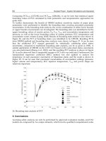
Table 3 gives indications that more than 40 % of the reportable events in Germany related to
high energy arcing faults have been reported since 2001. This underlines the increasing
relevance of this type of events.
Moreover, nearly half of those events, for which information regarding voltage level is not
available, are among the most recent events whereas usually specific information is more
difficult to collect for events in the far past. All these different activities and explanations of
the current state-of-the-art should be supported by the evaluation of the answers to the
German questionnaire.
Concerning high energy arcing fault events, short circuit failure of high voltage cables
(typically 10 kV) in cable rooms and cable ducts (channels, tunnels, etc.) is not assumed for
German nuclear power plants at the time being. Moreover, a failure of high voltage
switchgears (10 kV or more) and the resulting pressure increase are presumed to occur and
to be controlled.
Specific investigations with respect to such scenarios have resulted in additional measures
for pressure relief inside switchgear buildings of German nuclear power plants.
According to international fire testing standards (EN, 2009) fire barrier elements are
designed predominantly against the thermal impact of fires given by the standard fire curve
according ISO 834. The pressure build-up due to a HEAF is not considered as fire barrier
design load. In the course of several events fire barrier elements such as fire doors were
opened or deformed by a HEAF. One example is described in 5.7.
7. Concluding remarks and outlook
7.1 Improvement of the basic knowledge on HEAF
As soon as the questionnaire has been answered by the German nuclear power station
licensees, the answers will be statistically examined and interpreted. In particular, potential
Nuclear Power – Operation, Safety and Environment
150
consequences of events with this failure mechanism on equipment adjacent to that where
the high-energetic arcing faults occurred (particularly safety related equipment including
cables, fire protection features) as well as HEAF events in plant areas exceeding the typical
fire effects (smoke, soot, heat, etc.) shall be identified. The major goal of this task is to
provide first, still rough estimates on the contribution of high energy arcing faults events to
the core damage frequency.
The results of the German survey may reveal additional findings on the event causes,
possible measures either for event prevention or for limiting the consequences of such faults
such that nuclear safety is not impaired. In this context, additional generic results from the
OECD HEAF activity are expected.
A review of secondary effects of fires in nuclear power plants (Forell & Einarsson, 2010)
based to the OECD FIRE database showed that HEAFs did not only initiated fire event but
were also secondary effect of a fire. In two events included in the database, fire generated
smoke propagated to an adjacent electrical cabinet, which was ignited by a HEAF. This can
be interpreted as a special phenomenon of fire spread. In one case smoke from an intended
brush fire spread between the near 230 kV lines and caused a phase-to-phase arc.
As soon as the answers to the questionnaire have been analyzed in detail and the results
from the operation feedback are known, a discussion between licensees, reviewers and
regulators can be started on the general conclusions and potential back fitting measures and
improvements inside the nuclear installations.
Based on the international operating experience, state-of-the-art information and data on
high energy arcing faults of electric components and equipment shall be collected and
assessed with respect to the phenomena involved. In particular, potential consequences of
events with this failure mechanism on adjacent equipment (particularly safety related
equipment, fire protection features) and high energy arcing faults events in plant areas
exceeding the typical fire effects (smoke, soot, heat, etc.) shall be identified. Based on the
collected information and data a more comprehensive and traceable assessment can be
performed.
7.2 HEAF assessment
The high energy arcing fault assessment approach developed in (USNRC, 2005) primarily
represents an empirical model. As such, it depicts observations mainly based on a single
event and characterizes a damaging zone affected this event. To capture variations in
current and voltage level, insulation type and cabinet design a mechanistic model has been
developed (Hyslop et al., 2008).
Some recent studies have further developed the understanding of the high energy arcing
faults phenomena through experimentation and re-evaluation of previous theories.
Damage to cables and equipment by high energy impulses from arcing faults has been
shown to be different from that caused by fires alone. Specific components, such as
transformers, overhead power lines, and switchgears, have been identified as vulnerable to
arc events. However, when looking at the dynamic nature of high energy arcing faults, there
are still many factors being not well understood.
Computational fluid dynamics models have also been used to measure the pressure and
temperature increase (e.g. in switchgear rooms) and present reasonable results on arc events
(Friberg & Pietsch, 1999). However, fires were not evaluated.
The existing research is mainly limited in scope and has not yet addressed all factors
important to perform a full-scope probabilistic fire risk assessment including high energy
Investigation of High Energy Arcing Fault Events in Nuclear Power Plants
151
arcing faults. In general, high energy arcing faults events have been minimally explored but
improvements in the early quantitative results have been made. In particular, fire PSA
needs to assess the event behaviour beyond the initial arc-fault event itself (as past research
has focussed) so as to encompass the issues related to the enduring fire. Issues that go
beyond the initial arc fault event include the characterization of the potential for ignition of
secondary combustibles, characterization of the fire growth and intensity following the
enduring fire, and the effectiveness and timing of fire suppression efforts.
In order to improve the probabilistic fire safety assessment approach, further research
including experimental studies with respect to the arc mechanisms and phenomena as well
as to the damage criteria of the relevant equipment affected by high energy arcing faults is
needed. To better address the needs of probabilistic fire safety assessment, the scope of the
testing will need to be expanded as compared to past studies. These research activities will
be started in the U.S. in the near future (Hyslop et al., 2008), partially together with other
countries interested in high energy arcing faults and their significance.
7.3 Strategies for reducing arc flash hazards
An arc flash fault typically results in an enormous and nearly instantaneous increase in light
intensity in the vicinity of the fault. Light intensity levels often rise to several thousand
times normal ambient lighting levels. For this reason most, if not all, arc flash detecting
relays rely on optical sensors to detect this rapid increase in light intensity. For security
reasons, the optical sensing logic is typically further supervised by instantaneous over
current elements operating as a fault detector. Arc flash detection relays are capable of
issuing a trip signal in as little as 2.5 ms after initiation of the arcing fault (Inshaw & Wilson,
2004).
Arc flash relaying compliments existing conventional relaying. The arc flash detection relay
requires a rapid increase in light intensity to operate and is designed with the single
purpose of detecting very dangerous explosive-like conditions resulting from an arc flash
fault. It operates independently and does not need to be coordinated with existing relaying
schemes.
Once the arc flash fault has been detected, there are at least two design options. One option
involves directly tripping the upstream bus breakers. Since the arc flash detection time is so
short, overall clearing time is essentially reduced to the operating time of the upstream
breaker. A second option involves creating an intentional three-phase bus fault by
energizing a high speed grounding switch. This approach shunts the arcing energy through
the high-speed grounding switch and both faults are then cleared by conventional upstream
bus protection. Because the grounding switch typically closes faster than the upstream
breaker opens, this approach will result in lower incident energy levels than the first
approach. However, it also introduces a second three-phase bolted fault on the system and it
requires that a separate high speed grounding switch be installed and operational (Inshaw
& Wilson, 2004).
To prevent or alleviate HEAF effects, manufacturers have been working to develop arc
arrestors and arc detection methods and to improve composite materials in the switchgear
interior. The experiments conducted (see e.g. Jones et al., 2000) indicated that research and
testing are required to determine the voltage level, insulation type, and construction where
bus insulation may help extinguish or sustain arc once established. The use of such devices
would likely impact estimates of fire ignition frequency for such events, but no methods
currently exist to account for the presence, or absence, of such equipment.
Nuclear Power – Operation, Safety and Environment
152
8. References
Avendt, J.M. (2008). A time-current curve approach to flash-arc hazard analysis, United Service
Group, July 9, 2008
Berg, H. P.; Forell, B.; Fritze, N. & Röwekamp, M. (2009). First National Applications of the
OECD FIRE Database. Proceedings of SMiRT 20, 11th International Seminar on Fire
Safety in Nuclear Power Plants and Installations, August 17-19, 2009, Helsinki,
Finland, GRS-A-3496, paper 3.19
Berg, H.P.; Katzer, S.; Klindt, J. & Röwekamp, M. (2009). Regulatory and experts position on
HEAF and resulting actions in Germany, Proceedings of SMiRT 20, 11th International
Seminar on Fire Safety in Nuclear Power Plants and Installations, August 17-19, 2009,
Helsinki, Finland, GRS-A-3496, paper 3.12
Berg, H. P.; Fritze, N.; Forell, B. & Röwekamp, M. (2010). Risk oriented insights in
transformer fires at nuclear installations, Proceedings of the ESREL Conference 2010,
Rhodes, Taylor & Francis Group, London, pp. 354-361
Berg, H.P. & Fritze, N. (2011). Reliability of main transformers, Reliability and Risk Analysis:
Theory and Applications, in press
Brown, J.W., Nowlen, S.P. & Wyant, F.J. (2009). High energy arcing fault fires in switchgear
equipment, a literature review, Report SAND2008-4820, Sandia National Laboratories,
February 2009
Burkhart, E.F. (2009). The danger of arc flash, Fire Engineering, Vol. 162, Issue 7, July 1, 2009
Electricity Engineers´ Association - EEA (2010). Discussion paper on arc flash hazards,
December 2010
EN (2009). Fire classification of construction products and building elements - Part 2:
Classification using data from fire resistance tests, excluding ventilation services,
EN13501-2, September 2009
Forell, B. & Einarsson, S. (2010). A Survey of Secondary Effects from Fires in Nuclear Power
Plants, Proceedings of the ESREL Conference 2010, Rhodes, Taylor & Francis Group,
London, 1204-1209
Friberg, G. & Pietsch, G.J. (1999). Calculation of pressure rise due to arcing faults, IEEE
Transactions on Power Delivery, Vol. 14, No. 2, 365–370
HDI-Gerling (2009). Risk engineering guideline, fire protection in electrical equipment rooms, 04.09
Hyslop, J.S., Brown, J.W. & Nowlen, S.P. (2008). Considerations for improving fire PRA
treatment of high energy arcing faults, Proceedings of the ANS PSA 2008 Topical
Meeting, Knoxville, Tennessee, September 2008, on CD-ROM
Inshaw, C. & Wilson, R.A. (2004). Arc flash hazard analysis and mitigation, Western
Protective Conference, Spokane, WA, October 20
th
, 2004
Institute of Electronics and Electrical Engineers (IEEE). (2002). Guide for performing arc flash
hazard calculations, IEEE 1584, September 2002
International Atomic Energy Agency (IAEA). (2004). Experience gained from fires in nuclear
power plants: Lessons learned, IAEA-TECDOC-1421, November 2004
Jones, R.A., Liggett, D.P., Capelli-Schellpfeffer, M., Macalady, T. Saunders, L.F., Downey,
R.E., McClung, L.B., Smith, A., Jamil, S. & Saporita, V.J. (2000). Staged tests increase
awareness of arc-flash hazards in electrical equipment, IEEE Transactions on
Industry Applications, Vol. 36, No. 2, 659–667
Investigation of High Energy Arcing Fault Events in Nuclear Power Plants
153
Lane, J. (2004). Arc-flash hazard analysis, “Putting the pieces of the puzzle together”, November 8,
2004
Lang, M.J. (2005). Multiple hazards of arcing faults, Tech Topics: Arc Flash Note 1, Issue 1,
Ferraz Shawmut
Lippert K.J., Colaberardino, D.M. & Kimblin, C.W. (2005). Understanding IEEE 1584 arc
flash calculations, IEEE Industry Applications Magazine, 69 -75, May/June 2005
National Fire Protection Association (2009). NFPA 70E: Standard for Electrical Safety in the
Workplace
Nuclear Energy Agency (NEA), Committee on the Safety of Nuclear Installations. (2000).
Fire Risk Analysis, Fire Simulations, Fire Spreading and Impact of Smoke and Heat on
Instrumentation Electronics, NEA/CSNI/R(99)27, March 10, 2000
OECD/Nuclear Energy Agency (NEA), Committee on the Safety of Nuclear Installations
(CSNI). (2009). FIRE Project Report, “Collection and Analysis of Fire Events (2002-2008)
– First Applications and Expected Further Developments”, NEA/CSNI/R6 (2009), May
2009
OECD/Nuclear Energy Agency (NEA), Committee on the Safety of Nuclear Installations
(CSNI). (2009a), “Task on High Energy Arcing Events (HEAF)”, CAPS submitted to
CSNI / IAGE and to CSNI/PRG, Version 9 October 2008 – revised with PRG Chair
27 April 2009, Paris, 2009
Owen, E.D. (2011a). Arc flash: how extensive is this problem? Part I, Electrical Source
Magazine, January/February 2011, 33-35
Owen, E.D. (2011b). Arc flash: how extensive is this problem? Part II, Electrical Source
Magazine, March/April 2011, in press
Prasad, S. (2009). Arc flash hazard standards – the burning question, IDC Electrical Arc Flash
Forum, Melbourne, April 14 -15, 2010
Röwekamp, M. & Berg, H.P. (2008). PSA significance of events with electrically induced
high energy arcing faults, Proceedings of the International Conference on Probabilistic
Safety Assessment and Management (PSAM 9), Hong Kong May 18 - 23, 2008 (CD
ROM)
Roewekamp, M. & Liemersdorf, H. (1993). Analysis of fire events in nuclear power plants
and conclusions with respect to fundamental requirements concerning fire safety,
Proceedings of 3rd International Seminar on Fire Safety of Nuclear Power Plants, Held in
Conjunction with 12th International Conference on Structural Mechanics in Reactor
Technology (SMIRT 12), 23-24 August 1993, Heidelberg, Germany.
Kernforschungszentrum Karlsruhe, 103-126
Röwekamp, M., & Klindt, J. (2007). Questionnaire on High Energy Electric Arc Faults HEAF,
Draft including international comments, January 2007
Röwekamp, M., Frey, W., Klindt, J. & Katzer, S. (2009). Hochenergetisches elektrisches Versagen
von Schaltanlagen, Gesellschaft für Anlagen- und Reaktorsicherheit (GRS) mbH,
GRS-A-3485, Köln; August 2009
Röwekamp, M., Klindt, J. & Katzer, S. (2007). Internationaler Fragenkatalog zum
hochenergetischen elektrischen Versagen (High Energy Electric (Arc) Faults, HEEF,
December 2007
Nuclear Power – Operation, Safety and Environment
154
U.S. Nuclear Regulatory Commission and Electric Power Research Institute (2005).
EPRI/NRC-RES Fire PRA methodology for nuclear power facilities, Report NUREG/CR-
6850 and EPRI TR-1011989, September 2005
8
Research on Severe Accidents
in Nuclear Power Plants
Jean-Pierre Van Dorsselaere, Thierry Albiol and Jean-Claude Micaelli
Institut de Radioprotection et de Sûreté Nucléaire (IRSN)
France
1. Introduction
Severe accidents (SA) in nuclear power plants (NPPs) are unlikely events but with serious
consequences, as recently shown by the accident that occurred in April 2011 in the
Fukushima Japanese NPPs. SA research started originally in the seventies with initial risk
assessment studies and later on with experimental programs, development of numerical
simulation codes, and Level 2 Probabilistic Safety Assessments (PSA2). A huge amount of
research and development (R&D) was performed in the last thirty years in the international
frame. This was pushed forward by the two core meltdown accidents that occurred: first in
the Unit N°2 of the Three Mile Island (TMI-2) Pressurized Water Reactor (PWR) near
Harrisburg (Pennsylvania, USA) on March 28, 1979; then in the Chernobyl RBMK (Water-
cooled channel-type reactors with graphite as moderator, designed by Soviet Union) reactor
in Ukraine. Large progress has been reached in recent years on the understanding of SA but
several issues still need research activities to reduce uncertainties and consolidate the
accident management plans.
Along with the progress of understanding and the limited amount of the national budgets
on SA R&D, the high complexity of the physical phenomena and the high cost of
experiments made necessary to better rank the R&D needs. In 2004 the European
Commission judged necessary to better coordinate the national efforts to optimise the use of
the available expertise and the experimental facilities in order to resolve the remaining
issues for enhancing the safety of existing and future NPPs. This led to launch SARNET
(Severe Accident Research NETwork of Excellence) (Albiol et al., 2008; Micaelli et al., 2005),
in the framework of the 6
th
Framework Programme (FP6) of the European Commission,
gathering most worldwide actors on R&D SA. One of the main outcomes was the
identification of the highest priority SA issues still to be solved. A second phase of the
network (SARNET2 project) has started in April 2009, again supported by EC in the FP7 for
four years, again coordinated by IRSN.
Section 2 describes shortly what a severe accident is (most of the material described in this
section is issued from the reference IRSN-CEA, 2007). Section 3 presents the general
approach on SA R&D. Section 4 explains in details the approach that was adopted in
SARNET to rank the R&D priorities. Section 5 describes the current SARNET2 FP7 project
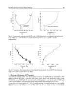
and the common research programmes, and finally Section 6 focuses, for the sake of
illustration, on the important issue of coolability of a degraded core during reflooding.
Nuclear Power – Operation, Safety and Environment
156
2. Severe accidents in nuclear power plants
2.1 Case of present nuclear power plants
The “severe accident” refers to an event with an extremely low probability of occurrence
(such as 10
-5
per reactor per year
1
for internal events), thanks to the preventive measures
implemented by NPP operators, but causing significant damage to the reactor core, with
more or less complete core meltdown and finally possible serious consequences in case of
release of radioactive products into the environment.
SAs are generally caused by a cooling failure within the reactor cooling system (RCS), which
prevents proper evacuation of residual power from the core, and by multiple dysfunctions,
arising from equipment and/or human error, including the failure of safety procedures. A
series of complex phenomena then occur, according to various scenarios and depending on
the initial conditions of the accident and on the operator actions. For the purpose of this
document, “early releases” are those liable to occur before all the measures aiming at
protecting the general public can be implemented. Figure 1 schematically presents the major
physical phenomena that may occur during a SA, as well as a few safety systems involved.
If the reactor core remains uncovered by water for an extended period of time (typically a
few hours), nuclear fuel progressively overheats due to residual power. Steam initiates an
exothermic oxidation of zircaloy fuel cladding, resulting in substantial production of
hydrogen and thermal power. Additionally, chemical reactions between fuel and its
cladding produce low-melting-point eutectics, resulting in relocation of molten materials
(called “corium”) in the core. The fuel first releases the most volatile fission products, then
the semi-volatile products.
Progressively, a corium pool forms in the core and progresses towards the lower head of the
vessel. When it reaches water remaining there, water is vaporized, corium is fragmented
and forms a debris bed. During core degradation, standby supplies of water can be
delivered to the RCS or the secondary cooling system. Reflooding a degraded core is a
complex phenomenon which may enable the accident progression to be slowed down or
halted under certain conditions. In contrast, reflooding may also increase hydrogen
production and cause further release of fission products.
Corium melts and debris accumulate in the vessel lower head and may cause its rupture,
either by thermal erosion, creep or plastic failure, depending on pressure conditions in the
RCS. After vessel rupture in case of high-pressure conditions within the vessel, part of the
ejected corium is fragmented and
may be dispersed into the containment. This may provoke a
pressure spike, resulting in substantial heat exchange with the air, oxidation of the corium
metallic components and, in some cases, simultaneous combustion of the hydrogen present in
the containment building. This phenomenon is called “direct containment heating” (DCH).
Following vessel rupture, corium slumps and accumulates in the reactor pit. A corium-
water interaction (called Fuel-Coolant Interaction or FCI) may occur if the pit contains some
water, which may be followed by a more violent phenomenon called steam explosion. This
explosion may create projectiles that could threaten the leak-tightness of the containment
buildings. Without initial presence of water in the pit, corium will thermally erode the
concrete basemat, which could cause the loss of containment: this is the Molten-Corium-
Concrete-Interaction or MCCI. During this phase, a substantial quantity of incondensable
gas (H
2
, CO, CO
2
) is released, resulting in a progressive increase in pressure within the
containment building. To avoid a potential break in this structure, a ventilation-filtration
1
This figure could be updated in the future, following the recent Fukushima accident.
Research on Severe Accidents in Nuclear Power Plants
157
Fig. 1. Main physical phenomena during a severe accident
system has been installed in all Light Water Reactors (LWR): it can be activated in general 24
hours after an accident begins, if the containment heat removal system fails.
Hydrogen produced by core degradation is released into the containment, where it burns on
contact with oxygen, provoking a pressure and temperature spike which may damage the
containment building. This combustion can either be slow acting (slow deflagration) or
more
rapid (rapid deflagration) and, in some cases, explosive (detonation). Hydrogen
combustion may lead to the loss of the containment barrier: a commitment to making this
risk residual has been demonstrated by the progressive implementation of hydrogen
Passive Autocatalytic Recombiners (PAR) in many NPPs.
For all modes of containment rupture, the release of fission products into the environment
depends on the conditions affecting their transfer within the reactor. The transfer of fission
products depends primarily on their physical and chemical properties, i.e. whether they are
gases or aerosols and their chemical form. Iodine and ruthenium behaviour requires
particular attention, given their complexity and their significant short-term radiological
impact. Regarding longer-term accident consequences, particular attention must be paid to
caesium releases.
In the event of a SA, operating personnel are called upon to follow the recommendations in
the Severe Accident Management Guidelines (SAMG). Actions recommended in the SAMG
serve primarily to maintain containment, aiming to:
- Avoid or minimise airborne radioactive releases outside the containment building,
- Provide sufficient time before potential containment loss to allow implementation of the
public protection measures described in emergency plans.
Nuclear Power – Operation, Safety and Environment
158
2.2 Case of future nuclear power plants
For all new NPPs of any type under construction or planned today, named “Generation III”
(noted Gen.III in the following), the provisions aim to significantly enhance accident
prevention and the SAs are addressed from the design phase.
For the EPR (European Pressurized Reactor), the technical directives specified that:
- Core meltdown accidents, particularly under pressurised conditions, postulated to
cause large early releases must be “practically eliminated”. While such accidents remain
physically possible, design measures must be implemented to prevent them. For
instance a dedicated pressurisation valve, coupled with an isolation valve, was
integrated in the RCS, in addition to the standard safety mechanisms protecting this
system from overpressure. PARs have also been installed in the containment.
- Low-pressure core meltdown sequences must proceed in such a way that the maximum
conceivable releases only require measures very limited in duration and scope to
protect the public. Thus a system was implemented to collect corium and stabilise it on
the long-term: this “core-catcher” is built in the containment building and linked to the
reactor pit. Besides, the containment has a double concrete wall, with filtration, to
increase the containment tightness with respect to radioactive release.
In other Gen.III NPPs, different designs have been elaborated for stopping corium
progression or limiting its consequences. Some NPPs aim at maintaining corium within the
vessel (In-Vessel-Retention or IVR) by cooling the external surface of the vessel lower head
through water injection into the pit. Others have designed core-catchers differently from the
EPR one that is based on corium spreading. Advanced VVERs
2
adopt a core-catcher
underneath the vessel (like the one at Tian Wan in China or being built in Belene in
Bulgaria): this core-catcher makes use of sacrificial materials consisting mainly of steel, iron
oxide ceramic and alumina.
3. Research and development on severe accidents
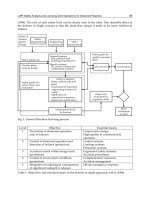
3.1 General approach
The general approach for SA R&D (Figure 2) is based on one hand on experiments and on
the other hand on computer codes for simulation of physical phenomena.
The SA R&D presents some specific features that imply very high costs:
- Complexity of the physical phenomena,
- High number of phenomena, with the need of considering them together due to their
mutual interactions (“coupling”),
- Extreme conditions: very high temperatures (above 3000°C), high pressure (up to 200
bars), irradiation effects,
- Need of tests with real materials (importance of the “material effect”),
- Difficulty to extrapolate to the reactor scale.
It has involved in the past very substantial human and financial resources as well as
collaboration between nuclear stakeholders, industry groups, research centres and safety
authorities, at both the national and international levels. The international programmes
concerned mainly the Framework Programmes of Research and Development of the
European Commission (see ) and the projects conducted under the
2
VVER: water-cooled water-moderated power reactors (PWR type) that were developed in the ex-
Soviet Union.
Research on Severe Accidents in Nuclear Power Plants
159
auspices of the CSNI (Committee on the Safety of Nuclear Installations) of NEA (Nuclear
Energy Agency) in the OECD (Organisation for Economic Cooperation and Development)
(CSNI, 2000; OECD, 2007).
The research in this area thus aims to further understand the physical phenomena and
reduce the uncertainties on their quantification, with the ultimate goal of physical
developing models that can be applied to reactors. These models, implemented in computer
codes, allow predicting SA progression and consequences.
Fig. 2. General R&D approach
For Gen.III NPPs, this research allowed to design specific devices for SA prevention and for
mitigation of consequences, as described in Section 2.2. However, for existing plants (called
Generation II and noted Gen.II in the following), SAs were not a design consideration.
Consequently, modifications of their design are limited and the research in this area is
primarily aimed at limiting the potential impact of SAs. Specifically, there are two
complementary research orientations: a) characterising releases and studying modes of
containment failure, and b) developing methods to limit the consequences of the SA scenarios.
3.2 Experimental R&D programmes
Different categories of experiments are usually defined:
Knowledge
improvement
Separate effect tests
Coupled effect tests
Integral tests
Models development
Experimental programmes
National - International
SA codes development, validation,
benchmarking
Data bases development
Knowledge
capitalization
Studies: deterministic (incl. source term
studies), level 2 PSA development
Safety analysis of nuclear installations
Knowledge valorisation
Emergency and post accidental situations
preparedness
Experience
feedback
Nuclear Power – Operation, Safety and Environment
160
Separate effect tests (SET) investigate a single phenomenon and yield data for
development of a model which describes its effect and which is to be integrated as a
sub-routine into a computer code. The corresponding facilities are typically single-
purpose, small-scale channels, loops or vessels equipped with specialised,
sophisticated, high-accuracy instrumentation.
Coupled effect tests (CET) investigate the coupling of two or more phenomena previously
explored in SETs, and provide data for the appropriate integration of the corresponding
models into a code. The corresponding facilities are typically of small to intermediate-
scale, using a test loop or a test vessel with comprehensive instrumentation adapted to
the effects to be investigated.
Integral Experiments represent all or part of a reactor accident sequence. They examine
the interactions of several phenomena previously studied in SETs and/or CETs. The
data obtained are needed for confirmatory validation of a code and its application, i.e.
adequate problem set-up by the code user, correct and complete modelling of the
relevant phenomena and their interactions within the code. The corresponding facilities
are typically intermediate to large-scale models of full size bundle or containment, in
the latter case with variable infrastructure for investigating many aspects of
containment behaviour.
3.3 Development of computer codes for SA numerical simulation
3.3.1 Types of codes
Three classes of SA codes can be defined, depending on their scope of application: integral
codes, detailed codes and dedicated codes.
Integral codes (also called “system” codes or, in the past “engineering-level” codes):
these codes simulate the overall NPP response, i.e. the response of the
RCS, the
containment, and the source term to the environment, using "integrated" models for a
self-consistent thorough analysis of the accident. They include a well-balanced
combination of phenomenological and user-defined parametric models for the
simulation of the relevant phenomena. They must be (relatively) fast running to enable
sufficient number of simulations of different scenarios to be performed, accompanied
by parameter studies to address uncertainties: the computing time should be roughly
around the accident real time. These codes are primarily not designed to perform Best-
Estimate simulations, but rather to allow the user to bound important processes or
phenomena by numerous user-defined parameters. Integral codes are usually used to
support PSA2 analyses and for the development and validation of Severe Accident
Management (SAM) programmes. In the last years, the rapid increase of the computer
performance enabled more and more the replacement of parametric models by
mechanistically based ones in the integral codes. The main internationally used codes
are today ASTEC (see Section 5.6), jointly developed by IRSN and GRS (Van
Dorsselaere et al., 2009), MAAP, developed by Fauske & Associates Inc. (USA), and
MELCOR, developed by Sandia National Laboratories (USA).
Detailed codes (also called mechanistic codes): they are characterised by best-estimate
phenomenological models, consistent with the state of the art, to enable as far as
possible an accurate simulation of the behaviour of a NPP in case of SA. In order to
better illustrate the differences with the approach of integral codes, in most cases, a
numerical solution is found for integral-differential equations while in integral codes
Research on Severe Accidents in Nuclear Power Plants
161
some correlations may be used. Basic requirements are that the modelling uncertainties
are comparable with the uncertainties on the experimental data used to validate the
code and that user-defined parameters are only necessary for phenomena that are not
understood due to insufficient experimental data (including scaling problems). Since, as
a basic principle, these codes should have as few as possible user options, existing
uncertainties in the simulation of the different phenomena must be specified to enable
the definition of the uncertainties of the key results. The main advantages of these codes
are to give a more detailed insight into the progression of a SA and to design and
optimise mitigation measures. They can also be used for benchmarking the integral
codes. Due to the high computation time, they simulate only a part of the plant, e.g.
RCS or containment. Their computation time depends on the scope of the application
but it can span over days and weeks. The main internationally used codes are today: for
the RCS behaviour and the core degradation ATHLET-CD (GRS), SCDAP/RELAP5
(INL in the USA), RELAP/SCDAPSIM (ISS in the USA) and ICARE/CATHARE (IRSN)
and for containment CONTAIN (ANL in the USA) and COCOSYS (GRS).
Dedicated codes: these codes that deal with a few phenomena have become important in
context with the requirements of the regulatory authorities to take into account SAs in
the design of new NPPs and to reduce uncertainties of risk-relevant phenomena. In
general they have to be very complex with the drawback of large calculation time.
Typical issues for which dedicated codes are required include: steam explosion and
melt dispersal (e.g. MC3D at IRSN), structure mechanics (e.g. CAST3M at CEA in
France, or ABAQUS in the USA). This family of codes includes the CFD (Computational
Fluid Dynamics) codes that solve Navier-Stokes thermal-hydraulics equations in 3D
geometry, such as GASFLOW in KIT (Germany), TONUS in IRSN, CFX as commercial
tool, etc….
3.3.2 Process of code development and validation
The general process of code development is composed of the following steps, with possible
iterations between them:
- Code requirements (scope
of application, computing time, etc…),
- General specifications (structure, programming language, level of details of modelling,
numerical schemes, etc…),
- Detailed specifications, possibly with prototyping to check a model or a numerical
scheme,
- Physical model development,
- Implementation into a computer code,
- Code verification (tests on analytic solutions of equations, laws of conservation of mass,
energy, and momentum, portability on diverse computers types, numerical coupling
between models, etc ).
The code validation process aims at providing a sufficiently accurate representation of the
reality of the SA phenomena. But this SA field presents some very peculiar features due to
the continuous evolution of knowledge and to the extreme conditions that occur in a SA,
notably the geometry scale that is difficult to achieve in laboratory experiments. The VASA
project (Allelein et al., 2001) took place in the FP4 of the European Commission to analyse
this SA validation process in details. Two stages can be defined:
Nuclear Power – Operation, Safety and Environment
162
Comparing the code results with results of experimental programmes, which leads to
define a “validation matrix”.
Verifying the code capability to adequately simulate real SA scenarios at full-scale,
which may be done through several types of work:
- Benchmarking the code results of plant applications with results of other codes,
either integral codes or detailed ones,
- Applying the code to real plant SA scenarios, which is very scarce except for the
TMI-2 and Chernobyl accidents (and in addition the Fukushima accident in the
future when reliable data become available),
- Performing uncertainty analyses in order to show the consistency and the
reliability of code results, including the analysis of the influence of nodalisation
and of numerical time-steps.
The CSNI International Standard Problems (ISP) provide a particularly valuable source of
information for code validation: they are comparative exercises in which predictions of
different computer codes for a given physical problem are compared with each other and
with the results of a carefully controlled and well documented experiment. Over the last
thirty years, forty-nine ISPs have been sponsored (CSNI, 2000).
The qualification of the code user is an important part of the code validation process. The
user may have an impact on the quality of the SA analysis. It is considered essential that
users have a good knowledge of the modelling inside the code and that the codes should not
be run as “black boxes”.
4. SARNET approach on severe accident R&D ranking
Most of the material described in the Section 4 is issued from the SARNET reference
(Schwinges et al., 2008).
4.1 Objectives and work scope of the SARP group
The EURSAFE thematic network (Magallon, 2005) yielded a list of 21 areas of needed
research in the SA domain, which included recommendations for experimental programmes
and code development. To further develop this list as a living document, the work package
“Severe Accident Research Priorities” (SARP) was established in the SARNET FP6 project.
The activities in SARP focused on the identification of areas where the knowledge has been
considerably improved and where further experimental research and/or model
development seemed not to be of high priority. Furthermore it had to identify research areas
which needed reorientation and, last but not least, the needed research not yet being
covered. The outcome of the SARP work was an up-dated ranking, giving different
priorities to the research issues, and helping (thus linking the last sentence to the previous
one ) decision to perform the different research programmes.
The working scope was outlined as:
- Agree on methodology,
- Identify issues resulting from EURSAFE not appropriately covered and review them,
- Analyse R&D recent progress,
- Analyse results from PSA2 studies,
- Reassess the ranking of research issues and reorient the priorities,
- Review potential experimental and theoretical programmes to address these issues,
- Make recommendations for revision of R&D programmes.
Research on Severe Accidents in Nuclear Power Plants
163
4.2 EURSAFE methodology and results
The objectives of EURSAFE were to establish a large consensus on the SA issues, where
large uncertainties still subsist, and to propose a structure to address these uncertainties by
appropriate R&D programmes making the best use of the European resources. It
incorporated issues related to existing plants (PWR, BWR
3
and VVER), lifetime extension of
these plants, evolutionary concepts (higher burn-up and mixed oxide –MOX- fuels), and
safety and efficiency of future systems. Twenty partners representing R&D governmental
institutions, regulatory bodies, nuclear industry, utilities and universities from nine
European countries and Canada worked together in a network structure, which was
supposed to be a starting point of SARNET.
To achieve the objectives, sufficient convergence on issues and phenomena and on their
importance in terms of safety and knowledge was required among all actors. The final
objective was a consensual approach to resolve the remaining uncertainties and open issues.
Establishing Phenomena Identification and Ranking Tables (PIRT) has been proved in other
areas (e.g. Loss of Coolant Accidents or LOCA) to be an efficient and unbiased way to reach
such a consensus (NUREG, 2000). In EURSAFE the PIRT integrated all the SA issues from
core degradation up to release of fission products from the containment, taking into account
any possible counter-measures and the evolution of fuel management.
As a basis, a comprehensive list of 1016 SA phenomena was established. The phenomena
were classified in five groups:
- In-vessel (162 phenomena),
- Ex-vessel (149 phenomena),
- Dynamic loading of the containment (461 phenomena),
- Long-term loading of the containment (116 phenomena),
- Fission products (128 phenomena).
Three safety-oriented groups of experts scrutinized these phenomena of the five lists and
ranked them in accordance to their safety importance for primary circuit, containment and
source term. Two evaluations were established: the safety importance ratio and the
knowledge ratio. Starting with 1016 identified phenomena, the list was reduced to 239 items,
important for safety, of which 106 were found with significant lack of knowledge.
After completion of the two ranking phases, this procedure clearly emphasized the
phenomena being simultaneously highly important for safety and significantly lacking of
knowledge. The remaining 106 phenomena were obviously candidates for further R&D
work:
- 24 phenomena for In-vessel,
- 28 phenomena for Ex-vessel,
- 26 phenomena for Dynamic loading of the containment,
- 10 phenomena for Long-term loading of the containment,
- 18 phenomena for Fission products.
As a further step, the research needs and programmes to address each selected phenomenon
of the PIRT list were identified and established in a list. According to the similarities in
terms of research needs and physical processes, with the scope of being able to set up a
limited number of coherent R&D programmes, several phenomena were merged into
research issues without further elimination or selection. A rationale for these research needs
3
Boiling Water Reactors