Nuclear Power Operation Safety and Environment Part 1 pdf
Bạn đang xem bản rút gọn của tài liệu. Xem và tải ngay bản đầy đủ của tài liệu tại đây (886.65 KB, 30 trang )
NUCLEAR POWER -
OPERATION, SAFETY
AND ENVIRONMENT
Edited by Pavel V. Tsvetkov
Nuclear Power - Operation, Safety and Environment
Edited by Pavel V. Tsvetkov
Published by InTech
Janeza Trdine 9, 51000 Rijeka, Croatia
Copyright © 2011 InTech
All chapters are Open Access articles distributed under the Creative Commons
Non Commercial Share Alike Attribution 3.0 license, which permits to copy,
distribute, transmit, and adapt the work in any medium, so long as the original
work is properly cited. After this work has been published by InTech, authors
have the right to republish it, in whole or part, in any publication of which they
are the author, and to make other personal use of the work. Any republication,
referencing or personal use of the work must explicitly identify the original source.
Statements and opinions expressed in the chapters are these of the individual contributors
and not necessarily those of the editors or publisher. No responsibility is accepted
for the accuracy of information contained in the published articles. The publisher
assumes no responsibility for any damage or injury to persons or property arising out
of the use of any materials, instructions, methods or ideas contained in the book.
Publishing Process Manager Petra Zobic
Technical Editor Teodora Smiljanic
Cover Designer Jan Hyrat
Image Copyright Andrea Danti, 2010. Used under license from Shutterstock.com
First published July, 2011
Printed in Croatia
A free online edition of this book is available at www.intechopen.com
Additional hard copies can be obtained from
Nuclear Power - Operation, Safety and Environment, Edited by Pavel V. Tsvetkov
p. cm.
ISBN 978-953-307-507-5
free online editions of InTech
Books and Journals can be found at
www.intechopen.com
Contents
Preface IX
Part 1 Operation and Safety 1
Chapter 1 World Experience in Nuclear Steam Reheat 3
Eugene Saltanov and Igor Pioro
Chapter 2 Integrated Approach for Actual Safety Analysis 29
Francesco D’Auria, Walter Giannotti and Marco Cherubini
Chapter 3 LWR Safety Analysis and Licensing
and Implications for Advanced Reactors 47
P. F. Frutuoso e Melo, I. M. S. Oliveira and P. L. Saldanha
Chapter 4 Geodetic Terrestrial Observations for the
Determination of the Stability in the
Krško Nuclear Power Plant Region 71
S. Savšek, T. Ambrožič and D. Kogoj
Chapter 5 Low Power and Shutdown PSA for the Nuclear
Power Plants with WWER440 Type Reactors 89
Zoltan Kovacs
Chapter 6 A Study on the Actuator
Efficiency Behavior of Safety-Related
Motor Operated Gate and Globe Valves 111
Shin Cheul Kang, SungKeun Park, DoHwan Lee,
YangSeok Kim and DaeWoong Kim
Chapter 7 Investigation of High Energy Arcing
Fault Events in Nuclear Power Plants 127
Heinz Peter Berg and Marina Röwekamp
Chapter 8 Research on Severe Accidents
in Nuclear Power Plants 155
Jean-Pierre Van Dorsselaere, Thierry Albiol
and Jean-Claude Micaelli
VI Contents
Chapter 9 Imaging of Radiation Accidents and Radioactive
Contamination Using Scintillators 183
Tomoya Ogawa, Nobuhiko Sarukura, Masahito Watanabe,
Tsuguo Fukuda, Nobuhito Nango, Yasunobu Arikawa,
Kohei Yamanoi, Tomoharu Nakazato, Marilou Cadatal-Raduban,
Toshihiko Shimizu, Mitsuo Nakai, Takayoshi Norimatsu,
Hiroshi Azechi, Takahiro Murata, Shigeru Fujino, Hideki Yoshida,
Kei Kamada, Yoshiyuki Usuki, Toshihisa Suyama, Akira Yoshikawa,
Nakahiro Sato, Hirofumi Kan, Hiroaki Nishimura, Kunioki Mima,
Masahito Hosaka, Masahiro Katoh, Nobuhiro Kosugi,
Kentaro Fukuda, Takayuki Yanagida, Yuui Yokota, Fumio Saito,
Kouhei Sakai, Dirk Ehrentraut, Mitsuru Nagasono, Tadashi Togashi,
Atsushi Higashiya, Makina Yabashi, Tetsuya Ishikawa,
Haruhiko Ohashi and Hiroaki Kimura
Chapter 10 Simulation of Ex-Vessel Steam Explosion 207
Matjaž Leskovar
Part 2 Environmental Effects 235
Chapter 11 Radiological Releases and Environmental
Monitoring at Commercial Nuclear Power Plants 237
Jason T. Harris
Chapter 12 Radiological and Environmental Effects in Ignalina
Nuclear Power Plant Cooling Pond – Lake Druksiai: From
Plant put in Operation to Shut Down Period of Time 261
Tatjana Nedveckaite, Danute Marciulioniene,
Jonas Mazeika and Ricardas Paskauskas
Chapter 13 Power Uprate Effect on Thermal Effluent of
Nuclear Power Plants in Taiwan 287
Jinn-Jer Peir
Part 3 Radiation Effects 303
Chapter 14 Long-Term Effects of Exposure to Low-Levels of
Radioactivity: a Retrospective Study of
239
Pu and
90
Sr from Nuclear Bomb Tests on the Swiss Population 305
Pascal Froidevaux, Max Haldimann and François Bochud
Chapter 15 The Biliprotein C-Phycocyanin Modulates the DNA
Damage Response in Lymphocytes from
Nuclear Power Plant Workers 327
K. Stankova, K. Ivanova, V. Nikolov, K. Minkova,
L. Gigova, R. Georgieva and R. Boteva
Chapter 16 Effects of Gamma-Ray Irradiation on Tracking
Failure of Polymer Insulating Materials 341
Boxue Du, Yu Gao and Yong Liu
Preface
Energy demands due to economic growth and increasing population must be satisfied
in a sustainable manner assuring inherent safety, efficiency and no or minimized
environmental impact. New energy sources and systems must be inherently safe and
environmentally benign. These considerations are among the reasons that lead to
serious interest in deploying nuclear power as a sustainable energy source. Today’s
nuclear reactors are safe and highly efficient energy systems that offer electricity and a
multitude of co-generation energy products ranging from potable water to heat for
industrial applications. At the same time, catastrophic earthquake and tsunami events
in Japan resulted in the nuclear accident that forced us to rethink our approach to
nuclear safety, design requirements and facilitated growing interests in advanced
nuclear energy systems, next generation nuclear reactors, which are inherently capable
to withstand natural disasters and avoid catastrophic consequences without any
environmental impact.
This book is one in a series of books on nuclear power published by InTech. Under the
single-volume cover, we put together such topics as operation, safety, environment,
and radiation effects. The book is not offering a comprehensive coverage of the
material in each area. Instead, selected themes are highlighted by authors of individual
chapters representing contemporary interests worldwide. Our book consists of three
major sections housing sixteen chapters:
Part 1. Operation and Safety
1. World Experience in Nuclear Steam Reheat
2. Integrated Approach for Actual Safety Analysis
3. LWR Safety Analysis and Licensing and Implications for Advanced Reactors
4. Geodetic Terrestrial Observations for the Determination of the Stability in the
Krško Nuclear Power Plant Region
5. Low Power and Shutdown PSA for the Nuclear Power Plants with WWER440
Type Reactors
6. A Study on the Actuator Efficiency Behavior of Safety-Related Motor
Operated Gate and Globe Valves
7. Investigation of High Energy Arcing Fault Events in Nuclear Power Plants
8. Research on Severe Accidents in Nuclear Power Plants
X Preface
9. Imaging of Radiation Accidents and Radioactive Contamination Using
Scintillators
10. Simulation of Ex-Vessel Steam Explosion
Part 2. Environmental Effects
11. Radiological Releases and Environmental Monitoring at Commercial Nuclear
Power Plants
12. Radiological and Environmental Effects in Ignalina Nuclear Power Plant
Cooling Pond – Lake Druksiai: From Plant put in Operation to Shut Down
Period of Time
13. Power Uprate Effect on Thermal Effluent of Nuclear Power Plants in Taiwan
Part 3. Radiation Effects
14. Long-Term Effects of Exposure to Low-Levels of Radioactivity: a
Retrospective Study of
239
Pu and
90
Sr from Nuclear Bomb Tests on the Swiss
Population
15. The Biliprotein C-Phycocyanin Modulates the DNA Damage Response in
Lymphocytes from Nuclear Power Plant Workers
16. Effects of Gamma-Ray Irradiation on Tracking Failure of Polymer Insulating
Materials
Our opening section is devoted to nuclear power operation and safety. The discussion
begins with an overview of nuclear steam supply systems that focuses on steam
reheat. The second chapter introduces the integrated safety analysis approach. Further
chapters introduce readers to licensing, probabilistic safety analysis, component
operation and safety. The section closes with chapters surveying approaches and
topics related to severe accident studies.
The second section is dedicated to environmental effects of nuclear power. Included
chapters address radiological release monitoring and consequences as well as thermal
prolusion.
The third and final section discusses radiation effects on general population, plant
workers and materials.
With all diversity of topics in 16 chapters, the integrated system analysis approach of
nuclear power operation, safety and environment is the common thread. The “system-
thinking” approach allows synthesizing the entire body of provided information into a
consistent integrated picture of the real-life complex engineering system – nuclear
power system – where everything is working together.
The goal of the book is to bring nuclear power to our readers as one of the promising
energy sources that has a unique potential to meet energy demands with minimized
environmental impact, near-zero carbon footprint, and competitive economics via
robust potential applications. The book targets everyone as its potential readership
Preface XI
groups - students, researchers and practitioners - who are interested to learn about
nuclear power. The idea is to facilitate intellectual cross-fertilization between field
experts and non-field experts taking advantage of methods and tools developed by
both groups. The book will hopefully inspire future research and development efforts,
innovation by stimulating ideas.
We hope our readers will enjoy the book and will find it both interesting and useful.
Pavel V. Tsvetkov
Department of Nuclear Engineering
Texas A&M University
United States of America
Part 1
Operation and Safety
1
World Experience in Nuclear Steam Reheat
Eugene Saltanov and Igor Pioro
University of Ontario Institute of Technology (UOIT)
Faculty of Energy Systems and Nuclear Science
Canada
1. Introduction
Concepts of nuclear reactors cooled with water at supercritical pressures were studied as
early as the 1950s and 1960s in the USA and Russia. After a 30-year break, the idea of
developing nuclear reactors cooled with SuperCritical Water (SCW) became attractive again
as the ultimate development path for water cooling. This statement is based on the known
history of the thermal power industry, which made a “revolutionary” step forward from the
level of subcritical pressures (15 – 16 MPa) to the level of supercritical pressures (23.5 – 35
MPa) more than fifty years ago with the same major objective as that of SuperCritcal Water-
cooled Reactors (SCWRs) − to increase thermal efficiency of power plants by 10 – 15%. The
main objectives of using SCW in nuclear reactors are: 1) to increase the thermal efficiency of
modern Nuclear Power Plants (NPPs) from 30 – 35% to about 45 – 50%, and 2) to decrease
capital and operational costs and hence, decrease electrical-energy costs.
To achieve higher thermal efficiency a nuclear steam reheat has to be introduced inside a
reactor. Currently, all supercritical turbines at thermal power plants have a steam-reheat
option. In the 60’s and 70’s, Russia, USA and some other countries have developed and
implemented the nuclear steam reheat at a subcritical pressure in experimental boiling
reactors. Therefore, it is important to summarize the experience of implementing nuclear
steam reheat at several experimental Boiling Water Reactors (BWRs) worldwide and utilize
it in the context of development of SCWRs with the steam-reheat option.
2. USA experience in nuclear steam reheat
An active program for the development and demonstration of BWRs with nuclear steam
reheat was implemented and directed by the United States Atomic Energy Commission
(USAEC). Two general types of the reactors were demonstrated:
1. Reactors in which steam was generated and reheated in the same core (integral
reheating design); and
2. Reactors, which only used reheated steam that was supplied from another source
(separate reheating design);
Under the USAEC program, the following reactors were constructed: BOiling Reactor
Experiment V (BORAX–V, started operation in December of 1962), BOiling NUclear
Superheater (BONUS, started operation in December of 1964), and Pathfinder (started
operation in July of 1966). Main parameters of these reactors are listed in Tables 1 and 2
(Novick et al. 1965).
Nuclear Power – Operation, Safety and Environment
4
At the design stage of these reactors a certain number of problems arising with the
implementation of steam reheat were encountered and addressed. Among them were:
1. Fuel-element sheath performance and corrosion resistance at high temperatures;
2. Corrosion, erosion, and deposits on fuel-element surfaces due to ineffective steam
separation prior to the reheating-zone inlet;
3. Maintenance of the desired power split in the evaporating and reheating zones during
extended reactor operation;
4. Fission products carry-over in direct-cycle systems; And
5. Reactivity changes as a result of inadvertent flooding of the reheating zone.
In search of the solutions to these problems USAEC also instituted a number of programs to
determine long-term integrity and behavior of the fuel-element sheath. Since May of 1959,
the Superheat Advance Demonstration Experiment (SADE) and the subsequent Expanded
SADE (ESADE) loops had been utilized to irradiate a total of 21 fuel elements in the
Vallecitos BWR. Saturated steam at about 6.9 MPa from the Vallecitos BWR was supplied to
the fuel-element section where it was superheated to temperatures of 418 – 480°C. The
results of those irradiation tests combined with out-of-core corrosion tests led to the
following conclusions (Novick et al. 1965):
1. Commercial 18-8 stainless steel (18-8 SS) was not satisfactory for fuel-sheath material in
the SuperHeated Steam (SHS) environment it was subjected to in the SADE and ESADE
experiments;
2. Materials with higher nickel-alloy content, such as Inconels and Incoloys, appeared to
perform satisfactorily as a sheath material in the SHS environment; And
3. Strain cycling coupled with environmental chemistry were significant in the failure rate
of sheath materials for reactors with the steam reheat.
Additional information on design of these reactors constructed under the USAEC program
can be found in USAEC reports 1959, 1961, and 1962 and in Ross (1961).
Parameters
BORAX–V BONUS Pathfinder
Zone Zone Zone
Boiling SHS Boiling SHS Boiling SHS
Structural
material (core)
A1(X8001) SS Zr–2 SS-248 Zr–2 SS
Fuel type Rod Plate Rod Rod Rod Annular
Fuel material UO
2
UO
2
–SS
cermet
UO
2
UO
2
UO
2
UO
2
–SS
cermet
Fuel enrichment,
%
4.95 93 2.4 3.25 2.2 93
Sheath material SS-304 SS-304L Zr–2 Inconel Zr–2 SS-316L
Control rod
shape
Cruciform
and "T"
Cruciform
and "T"
Cruciform Slab Cruciform Round rod
Control rod
material
Boral Boral
1.0%
wt
10
B
in SS
1.0%
wt
10
B
in SS
2%
wt
10
B in
SS
2%
wt
10
B in
SS
Average power
density,
MW
th
/m
3
42.5 40.5 33.6 11.5 45.2 46.5
Table 1. Main general parameters of BWR NPPs with integral reheat design (Novick et al.
1965).
World Experience in Nuclear Steam Reheat
5
Parameters BORAX–V BONUS Pathfinder
Electric
p
ower, MW
el
(g
ross
)
3.5 17.5 66
Electric
p
ower, MW
el
(
net
)
3.5 16.5 62.5
Thermal
p
ower, MW
th
20 50 200
Reheat loo
p
to eva
p
oratin
g
loo
p
p
ower ratio 0.21 0.35 0.22
Gross c
y
cle thermal efficienc
y
, % – 35 33
Net c
y
cle thermal efficienc
y
, % – 33 31
NPP steam c
y
cle Direct Direct Direct
Reheating-zone location
Central or
Peri
p
heral
Peripheral Central
Nominal o
p
eratin
g
p
ressure, MPa 4.1 6.7 4.1
Table 2. Main thermal parameters of BWR NPPs with integral reheat design (Novick et al.
1965).
The major conclusion, which is based on the USA experience with the nuclear steam reheat,
is that the nuclear steam reheat is possible, and higher thermal efficiencies can be achieved,
but this feature requires more complicated reactor-core design and better materials.
3. Russian experience in nuclear steam reheat
This section presents a unique compilation of materials that overviews all major aspects of
operating experience of the first in the world industrial NPP with implemented nuclear
steam reheat.
3.1 General information
Reactors with the nuclear steam reheat were also developed in the former Soviet Union.
Beloyarsk Nuclear Power Plant (BNPP) was the first NPP in the world where the nuclear
steam reheat was implemented. Two reactors (100 MW
e
and 200 MW
e
) were installed with
identical steam parameters at the turbine inlet (P
in
= 8.8 MPa and T
in
= 500 – 510C). The first
reactor (Unit 1) was put into operation on April 26, 1964, and the second reactor (Unit 2) −
on December 29, 1967. Both reactors have similar dimensions and design. However, the flow
diagram and the core arrangement were significantly simplified in Unit 2, compared to that
of Unit 1. Schematics and simplified layouts of the BNPP Units 1 and 2 are shown in Figures
1 and 2.
Operation of BNPP has proved the feasibility of steam-reheat implementation on an
industrial scale. Major results of the BNPP operation are listed below (Petrosyants 1969):
1. Reactor start-up from the cold state was achieved without external heat sources. The
reactor heat-up was carried out at 10% power until the water temperature in the
separators reached 285 – 300C at 8.8 MPa. Levels in the separators were formed during
heat-up. Transition from water to steam cooling in the SHS channels did not cause
significant reactivity changes.
2. The radial neutron flux flattening achieved was one of the best among operating
reactors. The radial neutron flux irregularity coefficient, K
ir
, for both units was 1.28 –
1.30, while the design values were: K
ir
= 1.46 for Unit 1 and K
ir
= 1.24 for Unit 2.
3. Radioactivity in the turbine and technological equipment of the plant is an important
indicator for NPP. Radiation rates at the high-pressure cylinders were not higher than
10 µR/s and not higher than 8 µR/s at the low-pressure cylinders. Such low dose rates
Nuclear Power – Operation, Safety and Environment
6
were attained by implementation of fuel elements that eliminated the possibility of
fission-fragment activity transported via the coolant loop. BNPP operation experience
showed that radiation levels near Unit 1 equipment were significantly lower than that
of other operating reactors, and releases of radioactive products into the atmosphere
were 5 – 10 times lower than allowed by codes.
(a)
(b)
– Reheated steam; – Saturated steam;
– Water-steam mixture; – Water.
Fig. 1. BNPP Unit 1 (a) and Unit 2 (b) general schematics of thermodynamic cycle
(Yurmanov et al. 2009a):
(a)
(b)
Fig. 2. Simplified layout of BNPP Unit 1 (a) and Unit 2 (b) (Petrosyants 1969): 1 – circulation
pump; 2 – reactor; 3 – Boiling Water (BW) channels; 4 – SHS channels; 5 – steam separator; 6
– Steam Generator (SG); 7 – economizer; 8 – bubbler; and 9 – Feed Water Pump (FWP).
3.2 Cycle development
Reliability, simple design, and efficiency are the main criteria when choosing the flow
diagram for both the fossil and nuclear power plants. Special requirements for
impermeability and water regime are specified for NPPs. Additionally, the reasonable
development of temperature regimes for fuel channels allows safe power increase for the a
reactor size.
Several layouts of thermodynamic cycles for a NPP with a uranium-graphite reactor were
considered for the BNPP (see Figure 3). In the considered layouts the coolant was either
boiling water or superheated steam. Feasibility of the NPP designs was also taken into
account (Dollezhal et al. 1958).
World Experience in Nuclear Steam Reheat
7
(a)
(b)
(c)
Nuclear Power – Operation, Safety and Environment
8
(d)
(e)
(f)
Fig. 3. Possible layouts of NPPs with steam reheat (Dollezhal et al. 1958): 1 – reactor; 2 –
steam separator; 3 – SG; 4 – Main Circulation Pump (MCP); 5 – circulation pump; 6 – turbine
with electrical generator; 7 – FWP; and 8 – intermediate-steam reheater.
World Experience in Nuclear Steam Reheat
9
Layout (a). A steam separator, steam generator (consisting of preheating, boiling and steam-
superheating sections), and two circulation pumps are included in the primary coolant loop.
Water and very high-pressure steam are the primary coolants. High- and intermediate-
pressure steam is generated in the secondary loop and directed to the turbine.
Layout (b). Direct-cycle layout. Steam from a reactor flows directly to a turbine. The turbine
does not require an intermediate-steam reheat.
Layout (c). Steam from a reactor flows directly to a turbine. The turbine requires the
intermediate-steam reheat. The reactor has three types of operating fuel channels: 1) water
preheating, 2) evaporating-boiling, and 3) steam-superheating.
Layout (d). Direct-cycle layout. The evaporation and reheat are achieved inside a reactor.
The turbine does not require the intermediate-steam reheat.
Layout (e). Direct-cycle layout. One or two intermediate-steam reheats are required.
Layout (f). Water circulates in the closed loop consisting of a reactor, steam separator,
preheater, and circulation pump. Partial evaporation is achieved in the first group of
channels. Steam exiting the steam separator is directed to the boiling section of the steam
generator and condenses there. Condensate from the boiler is mixed with water from the
separator. The cooled water is fed to a preheater and then directed to circulation pumps.
The generated steam on the secondary side is superheated in the second group of channels
and then directed to the turbine.
Layouts (b–e) were not recommended due to unpredictable water-chemistry regimes at
various locations throughout the thermodynamic cycle. Layout (a) with the secondary-
steam reheat required high pressures and temperatures in the primary loop. Circulation
pumps with different parameters (power and pressure) were used to feed common header
upstream of the channels of the primary group. In this respect, Layout (a) was considerably
more complex and expensive than Layout (f). Activation of SHS, which could occur in
Layout (f), was not considered to be posing any significant complications to the turbine
operation, and hence remained a viable option (Dollezhal et al. 1958).
From the considerations above, Layout (f) was chosen to be developed at the BNPP Unit 1.
Surface-corrosion products in the secondary loop and salts in condenser coolant were
trapped in the steam generator and removed from it during purging. Additionally, modern
separators provided steam of high quality, which resulted in very low salt deposits in the
turbine.
3.3 Beloyarsk NPP reactor design
The reactor was placed in a cylindrical concrete cavity, where a 3-m thick wall served as a
part of the biological shield. A cooled ferro-concrete base of the reactor with six base jacks
was implemented on the bottom of the cavity. The bottom bedplate attached to the bottom
supporting ring was held by jacks. Cooling coils were placed on the bottom of the bedplate
to provide its cooling.
The cylindrical graphite stack (3 m in diameter and 4.5 m in height) of the reactor was
installed on the bottom bedplate. The stack was made of columns, assembled of hexagonal
blocks (0.12-m width across corners) in the center and of sectors in the periphery. The
central part of the stack was penetrated by vertical operating channels (long graphite
cylinders containing inner thin steel tubes with fuel elements). The reactor core (7.2-m
diameter and 6-m height) was surrounded with a 0.8-m thick graphite reflector. An
additional 1-m thick graphite layer and an approximately 0.5-m cast-iron layer over the
upper reflector formed the principal part of the biological shield. A 0.6-m thick graphite
layer serving as the lower neutron shield was located below the lower reflector.
Nuclear Power – Operation, Safety and Environment
10
The graphite stack (9.6-m overall diameter and 9.0-m height) was enclosed in a gas-tight
cylindrical carbon-steel shell filled with nitrogen to prevent graphite deterioration. The
outer graphite blocks were penetrated by steel uprights with horizontal lateral braces in
several places along their height. The entire stack rested on the bottom bedplate. The
graphite stack was covered on the top with a plate carrying standpipes with openings for
the insertion of operating channels. The piping for feeding the coolant to the fuel bundles
and for removing the coolant water from control rods was located between the
standpipes. The piping of the operating channels and protective coating failure-detection
system was also located between the standpipes. The plate rested on supports installed on
the tank of the side water shield. The plate was connected with the graphite stack shell by
means of a compensator, which allowed both for vertical elongations of the shell and
horizontal elongations of the plate, which occurred during heating (Emelyanov et al.
1982).
As shown in Figure 4, the reactor had 1134 operating channels and contained 998 fuel
channels, 6 automatic control rods, 78 channels for reactivity compensating rods, 16 shut-
down rods, and 36 channels for ionization chambers and counters. The fuel channels were
represented with 730 BW channels, also referred to as evaporating channels, and 268 SHS
channels, also referred to as steam-reheat channels.
The main parameters of the BNPP reactors are listed in Table 3.
3.4 Physical parameters of Beloyarsk NPP reactors
Flattening of a power distribution was achieved at the BNPP with physical profiling:
appropriate distribution of control rods and fuel channels of different uranium enrichment
(for fresh load) and profiling of burn-up fuel along the reactor radius. The reactor load
consisted of SHS channels of 2% and 3% uranium enrichments (SHS-2 and SHS-3,
respectively) and BW channels. The BW channels were located in rings in alternate locations
with SHS-2. SHS-3 were located along the circumference and had lower pressure losses in
the steam circuit (Dollezhal et al. 1964).
Neutronics calculations were made to choose optimal distribution of channels to achieve
required power shape. Most of the calculations for the core-reactor physics were
performed in the 2-group approximation. In accordance with the fuel-channels
distribution the core was represented by four cylindrical regions with the radii: R
1
= 175
cm (234 fuel channels), R
2
= 268 cm (324 fuel channels), R
3
= 316 cm (220 fuel channels),
and R
4
= 358 cm (220 fuel channels). The previous calculations and operating experience
of large uranium-graphite reactors with relatively small neutron leakage showed that a
simplified schematic could be used when neutron distribution in the reactor is determined
by the multiplication characteristics of the reactor regions. The multiplications constants
obtained for the 4 regions (k
inf,1
= 1.013, k
inf,2
= 1.021, k
inf,3
= 1.043, and k
inf,4
= 1.045) allowed
flattening of the neutron distribution along the reactor radius with K
ir
= 1.20 – 1.25. The
increase in the multiplication constants values to the periphery of the reactor was attained
by placing fuel channels with 3% uranium enrichment. Refuelling schemes and, therefore,
fuel burn-up at different regions were chosen such as to allow designed power flattening
in the end of the campaign, with corresponding values of k
inf,i
. Control rods insertion in
the core maintained k
inf,i
values in the necessary limits during normal operation (Vikulov
et al. 1971).
World Experience in Nuclear Steam Reheat
11
Fig. 4. BNPP Unit 1 channels layout (Pioro et al. 2010, this figure is based on the paper by
Dollezhal et al. 1958).
Nuclear Power – Operation, Safety and Environment
12
Parameters
BNPP Unit 1
(730 BWs & 268 SHSs)
BNPP Unit 2
(732 BWs & 266 SHSs)
Electrical power, MW
el
100 200
Number of K-100-90-type turbines 1 2
Inlet-steam pressure, MPa 8.5 7.3
Inlet-steam temperature, ºC 500 501
Gross thermal efficiency, % 36.5 36.6
Total metal content (top & bottom plates,
vessel, biological shielding tank, etc.), t
1800 1800
Weight of separator drums, t 94 156
Weight of circulation loop, t 110 110
Weight of graphite stacking, t 810 810
Uranium load, t 67 50
Specific load, MW
th
/t 4.3 11.2
Uranium enrichment, % 1.8 3.0
Specific electrical-energy production,
MW
el
days/t
4000 10000
Square lattice pitch, mm 200 200
Core dimensions, m: Diameter
Height
7.2
6
7.2
6
Table 3. Main parameters of BNPP reactors (Aleshchenkov et al. 1964; Dollezhal et al. 1969,
1971).
One of the requirements to be met when implementing nuclear steam reheat is to maintain a
constant specified power split (π) between SHS and BW channels during the operating
period. The SHS channel temperature up to 520C at the BNPP was obtained by setting
=
0.41 at the optimum parameters of the thermodynamic cycle. The number of SHS channels
was chosen to provide a
-value of 0.41 at the partial refuelling scheme where the K
ir
1.25.
The steady-state regime was characterized with small fluctuations of approximately 1% in
the
-value between the refuellings. Circular arrangement of SHS channels (Unit 1) had an
advantage of small
-sensitivity to the changes in radial neutron flux distributions, while for
central arrangement of SHS channels (Unit 2)
values were more sensitive (see Table 4).
0.408 0.429 0.452 0.494
K
eff
1.20 1.36 1.53 1.78
Table 4. Steam-superheating-zone power to boiling-zone power ratio (
) dependence on
neutron flux K
eff
for BNPP Unit 2 (Vikulov et al. 1971).
However, preference was given to the central arrangement of SHS channels, because this
allowed attaining a higher
-value (around 12% higher) with the same number of SHS
channels. Additionally, central arrangement of SHS channels provided better multiplication
characteristics than BW channels. SHS channels were placed in the central region to increase
average fuel burn-up by 10%. It should be noted, that during the initial operation period the
burn-up rates were different for BW and SHS channels of fresh load, which led to an
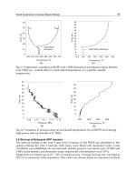
unbalance of power between superheating and boiling zones. Figure 5 shows the calculated
World Experience in Nuclear Steam Reheat
13
dependence of
-values and power variations for different types of fuel channels on the
power generated by the reactor (Vikulov et al. 1971).
Calculations were performed assuming K
ir
1.25. A fast decrease in the superheating-zone
power relative to that of the boiling zone in the initial period was accounted for by a lower
power change in SHS channels due to slightly higher fuel conversion in the low enriched SHS-
2. Practically achieved values of K
ir
were approximately 1.4 for Unit 1 and 1.3 for Unit 2.
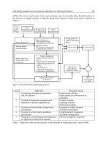
One of the features of the uranium-graphite reactors cooled with water is the possibility of
reactivity change with water-content change in the reactor. Substitution of boiling water with
steam in the operating channels leads to the rapid change of coolant average density. Failure of
a fuel-element sheath is another possibility of water-content change that was considered while
designing the BNPP reactors. The chosen core lattice with respect to reactivity change turned
out to be weakly dependent on water-content changes. It was explained by the compensation
of effects of increased resonance neutrons captured by increased water content and an increase
at the same time of non-productive neutrons absorption (Dollezhal et al. 1964). Normalized
thermal-neutrons distribution along the operating channel cell was studied experimentally for
the reactor lattice as shown in Figure 6
Fig. 5. Channel power ratios and power split between SHS and BW channels (
)
dependences on burnup produced by BNPP Unit 2 during the first operating period
(Vikulov et al. 1971): SHS-3 – superheated steam channel with 3% uranium enrichment and
SHS-2 – superheated steam channel with 2% uranium enrichment.