Standard Methods for Examination of Water & Wastewater_4 potx
Bạn đang xem bản rút gọn của tài liệu. Xem và tải ngay bản đầy đủ của tài liệu tại đây (1.98 MB, 49 trang )
Screening, Settling,
and Flotation
Screening
is a unit operation that separates materials into different sizes. The unit
involved is called a
screen
. As far as water and wastewater treatment is concerned,
only two “sizes” of objects are involved in screening: the water or wastewater and
the objects to be separated out.
Settling
is a unit operation in which solids are
drawn toward a source of attraction. In gravitational settling, solids are drawn
toward gravity; in centrifugal settling, solids are drawn toward the sides of cyclones
as a result of the centrifugal field; and in electric-field settling, as in electrostatic
precipitators, solids are drawn to charge plates.
Flotation
is a unit operation in
which solids are made to float to the surface on account of their adhering to minute
bubbles of gases (air) that rises to the surface. On account of the solids adhering
to the rising bubbles, they are separated out from the water. This chapter discusses
these three types of unit operations as applied to the physical treatment of water
and wastewater.
5.1 SCREENING
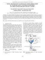
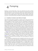
Figure 5.1 shows a bar rack and a traveling screen. Bar racks (also called bar
screens) are composed of larger bars spaced at 25 to 80 mm apart. The arrangement
shown in the figure is normally used for shoreline intakes of water by a treatment
plant. The rack is used to exclude large objects; the traveling screen following it is used
to remove smaller objects such as leaves, twigs, small fish, and other materials that
pass through the rack. The arrangement then protects the pumping station that lifts
this water to the treatment plant. Figure 5.2 shows a bar screen installed in a detritus
tank. Detritus tanks are used to remove grits and organic materials in the treatment
of raw sewage. Bar screens are either hand cleaned or mechanically cleaned. The
bar rack of Figure 5.1 is mechanically cleaned, as shown by the cable system hoisting
the scraper; the one in Figure 5.2 is manually cleaned. Note that this screen is
removable. Table 5.1 shows some design parameters and criteria for mechanically
and hand-cleaned screens.
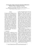
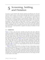
Figure 5.3 shows a microstrainer. As shown, this type of microstrainer consists
of a straining material made of a very fine fabric or screen wound around a drum.
The drum is about 75% submerged as it is rotated; speeds of rotation are normally
about from 5 to 45 rpm. The influent is introduced from the underside of the wound
fabric and exits into the outside. The materials thus strained is retained in the interior
of the drum. These materials are then removed by water jets that directs the loosened
strainings into a screening trough located inside the drum. In some designs, the flow
is from outside to the inside.
5
TX249_Frame_C05 Page 243 Friday, June 14, 2002 4:27 PM
© 2003 by A. P. Sincero and G. A. Sincero
244
Microstrainers have been used to remove suspended solids from raw water
containing high concentrations of algae. In the treatment of wastewater using oxi-
dation ponds, a large concentration of algae normally results. Microstrainers can be
used for this purpose in order to reduce the suspended solids content of the effluent
FIGURE 5.1
Bar rack and traveling screen. (Courtesy of Envirex, Inc.)
FIGURE 5.2
Bar screen in a detritus tank.
Traveling screen
Bar rack
Rake can reach
to bottom of
tank
Detritus
tank
Outlet
Inlet
Heavy solids
pit
Section A-A
Penstocks
Plan
Inlet
Inlet
Detritus
To sludge feed
(a)
(b)
A
A
h
1
h
1
– h
2
h
2
12
TX249_Frame_C05 Page 244 Friday, June 14, 2002 4:27 PM
© 2003 by A. P. Sincero and G. A. Sincero
245
that may cause violations of the discharge permits of the plant. Microstrainers have
also been used to reduce the suspended solids content of wastewaters treated by
biological treatment. Openings of microstrainers are very small. They vary from 20
to 60
µ
m and the cloth is available in stainless steel or polyester construction.
5.1.1 H
EAD
L
OSSES
IN
S
CREENS
AND
B
AR
R
ACKS
Referring to
b
of Figure 5.2, apply the Bernoulli equation, reproduced below, between
points 1 and 2.
(5.1)
where
P
,
V
, and
h
are the pressure, velocity, and elevation head at indicated points;
g
is the acceleration due to gravity.
V
1
is called the
approach velocity
; the channel
in which this velocity is occurring is called the
approach channel
. To avoid sedi-
mentation in the approach channel, the velocity of flow at this point should be
maintained at the self-cleansing velocity. Self-cleansing velocities are in the neigh-
borhood of 0.76 m/s.
TABLE 5.1
Design Parameters and Criteria for Bar Screens
Parameter Mechanically Cleaned Manually Cleaned
Bar size
Width, mm 5–20 5–20
Thickness, mm 20–80 20–80
Bars clear spacing, mm 20–50 15–80
Slope from vertical, degrees 30–45 0–30
Approach velocity, m/s 0.3–0.6 0.6–1.0
FIGURE 5.3
A Microstrainer. (Courtesy of Envirex, Inc.)
Influent
Screening
return
Grid
Effluent
Screening
trough
Backwash spray
P
1
γ
V
1
2
2g
h
1
++
P
2
γ
V
2
2
2g
h
2
++=
TX249_Frame_C05 Page 245 Friday, June 14, 2002 4:27 PM
© 2003 by A. P. Sincero and G. A. Sincero
Remember from fluid mechanics that the Bernoulli equation is an equation for
frictionless flow along a streamline. The flow through the screen is similar to the
flow through an orifice, and it is standard in the derivation of the flow through an
orifice to assume that the flow is frictionless by applying the Bernoulli equation. To
consider the friction that obviously is present, an orifice coefficient is simply prefix
to the derived equation.
Both points 1 and 2 are at atmospheric, so the two pressure terms can be canceled
out. Considering this information and rearranging the equation produces
(5.2)
From the equation of continuity,
V
1
may be solved in terms
V
2
, cross-sectional area
of clear opening at point 2 (
A
2
), and cross-sectional area at point 1 (
A
1
).
V
1
is then
V
1
=
A
2
V
2
/
A
1
. This expression may be substituted for
V
1
in the previous equation,
whereupon,
V
2
can be solved. The value of
V
2
thus solved, along with
A
2
, permit the
discharge
Q
through the screen openings to be solved. This is
(5.3)
Recognizing that the Bernoulli equation was the one applied, a coefficient of
discharge must now be prefixed into Equation (5.3). Calling this coefficient
C
d
,
(5.4)
Solving for the head loss across the screen
∆
h
,
(5.5)
As shown in Equation (5.5), the value of the coefficient can be easily determined
experimentally from an existing screen. In the absence of experimentally determined
data, however, a value of 0.84 may be assumed for
C
d
. As the screen is clogging, the
value of
A
2
will progressively decrease. As gleaned from the equation, the head loss
∆
h
will theoretically rise to infinity. At this point, the screen is, of course, no longer
functioning.
The previous equations apply when an approach velocity exists. In some situa-
tions, however, this velocity does not exist. In these situations, the previous equations
do not apply and another method must be developed. This method is derived in the
next section on microstrainers.
V
1
2
V
2
2
2gh
2
h
1
–()+=
QA
2
V
2
A
2
2gh
1
h
2
–()
1
A
2
A
1
–
A
2
2g∆h
1
A
2
A
1
–
== =
QC
d
A
2
2g∆h
1
A
2
A
1
–
=
∆h
Q
2
1
A
2
A
1
–
2gC
d
2
A
2
2
=
TX249_Frame_C05 Page 246 Friday, June 14, 2002 4:27 PM
© 2003 by A. P. Sincero and G. A. Sincero
247
5.1.2 H
EAD
L
OSS
IN
M
ICROSTRAINERS
Referring to Figure 5.3, the flow turns a right angle as it enters the openings of the
microstrainer cloth. Thus, the velocity at point 1,
V
1
, (refer to Figure 5.2) would
be approximately zero. Therefore, for microstrainers: applying the Bernoulli equa-
tion, using the equation of continuity, and prefixing the coefficient of discharge as
was done for the bar screen, produce
(5.6)
As in the bar screen, the value of the coefficient can be easily determined
experimentally from an existing microstrainer. In the absence of experimentally
determined data, a value of 0.60 may be assumed for
C
d
. Also, from the equation,
as the microstrainer clogs, the value of
A
2
will progressively decrease; thus the head
loss rises to infinity, whereupon, the strainer ceases to function. Although the pre-
vious equation has been derived for microstrainers, it equally applies to ordinary
screens where the approach velocity is negligible.
Example 5.1
A bar screen measuring 2 m by 5 m of surficial flow area is used
to protect the pump in a shoreline intake of a water treatment plant. The plant is
drawing raw water from the river at a rate of 8 m
3
/s. The bar width is 20 mm and
the bar spacing is 70 mm. If the screen is 30% clogged, calculate the head loss
through the screen. Assume
C
d
=
0.60.
Solution:
For screens used in shoreline intakes, the velocity of approach is practically
zero. Thus,
From the previous figure, the number of spacings is equal to one more than the
number of bars. Let x = number of bars,
∆h
Q
2
2gC
d
2
A
2
2
=
5 m
20 mm
70 mm
∆h
Q
2
2gC
d
2
A
2
2
=
TX249_Frame_C05 Page 247 Friday, June 14, 2002 4:27 PM
© 2003 by A. P. Sincero and G. A. Sincero
Therefore,
Example 5.2 In the previous example, assume that there was an approach
velocity and that the approach area is 7.48 m
2
. Calculate the head loss.
Solution:
Assume C
d
= 0.84
5.2 SETTLING
Settling has been defined as a unit operation in which solids are drawn toward a
source of attraction. The particular type of settling that will be discussed in this section
is gravitational settling. It should be noted that settling is different from sedimenta-
tion, although some authors consider settling the same as sedimentation.
Strictly speaking, sedimentation refers to the condition whereby the solids are
already at the bottom and in the process of sedimenting. Settling is not yet sedi-
menting, but the particles are falling down the water column in response to gravity.
Of course, as soon as the solids reach the bottom, they begin sedimenting. In the
physical treatment of water and wastewater, settling is normally carried out in settling
or sedimentation basins. We will use these two terms interchangeably.
Generally, two types of sedimentation basins are used: rectangular and circular.
Rectangular settling basins or clarifiers, as they are also called, are basins that are
rectangular in plans and cross sections. In plan, the length may vary from two to
four times the width. The length may also vary from ten to 20 times the depth. The
depth of the basin may vary from 2 to 6 m. The influent is introduced at one end
and allowed to flow through the length of the clarifier toward the other end. The
solids that settle at the bottom are continuously scraped by a sludge scraper and
20x 70 x 1+()+ 5000=
x 54.77, say 55=
Area of clear opening 70 55 1+()2000()=
7,840,000 mm
2
= 7.48 m
2
A
2
==
∆h
8
2
2 9.81()0.6()
2
7.48 0.7()[]
2
0.33 m of water==
∆h
Q
2
1
A
2
A
1
–
2gC
d
2
A
2
2
=
∆h
8
2
1
7.48 0.7()
52()
–
2 9.81()0.84
2
()7.48 0.7()[]
2
30.49
379.54
0.08 m of water===
TX249_Frame_C05 Page 248 Friday, June 14, 2002 4:27 PM
© 2003 by A. P. Sincero and G. A. Sincero
removed. The clarified effluent flows out of the unit through a suitably designed
effluent weir and launder.
Circular settling basins are circular in plan. Unlike the rectangular basin, circular
basins are easily upset by wind cross currents. Because of its rectangular shape,
more energy is required to cause circulation in a rectangular basin; in contrast, the
contents of the circular basin is conducive to circular streamlining. This condition
may cause short circuiting of the flow. For this reason, circular basins are typically
designed for diameters not to exceed 30 m in diameter.
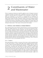
Figure 5.4 shows a portion of a circular primary sedimentation basin used at the
Back River Sewage Treatment Plant in Baltimore City, MD. In this type of clarifier,
the raw sewage is introduced at the center of the tank and the solids settled as the
wastewater flows from the center to the rim of the clarifier. The schematic elevational
section in Figure 5.5 would represent the elevational section of this clarifier at the
FIGURE 5.4 Portion of a primary circular clarifier at the Back River Sewage Treatment Plant,
Baltimore City, MD.
FIGURE 5.5 Elevation section of a circular radial clarifier. (Courtesy of Walker Process.)
Effluent weir
Effluent
weir
Drive
Influent well
Sludge draw-off
Effluent
Influent
Sludge concentrator
Collector arm
TX249_Frame_C05 Page 249 Friday, June 14, 2002 4:27 PM
© 2003 by A. P. Sincero and G. A. Sincero
Back River treatment plant. As shown, the influent is introduced at the bottom of the
tank. It then rises through the center riser pipe into the influent well. From the center
influent well, the flow spreads out radially toward the rim of the clarifier. The clarified
liquid is then collected into an effluent launder after passing through the effluent weir.
The settled wastewater is then discharged as the effluent from the tank.
As the flow spreads out into the rim, the solids are deposited or settled along
the way. At the bottom is shown a squeegee mounted on a collector arm. This arm
is slowly rotated by a motor as indicated by the label “Drive.” As the arm rotates,
the squeegee collects the deposited solids or sludge into a central sump in the tank.
This sludge is then bled off by a sludge draw-off mechanism.
Figure 5.6a shows a different mode of settling solids in a circular clarifier. The
influent is introduced at the periphery of the tank. As indicated by the arrows, the
flow drops down to the bottom, then swings toward the center of the tank, and back
into the periphery, again, into the effluent launder. The solids are deposited at the
bottom, where a squeegee collects them into a sump for sludge draw-off.
Figure 5.6b is an elevational section of a rectangular clarifier. In plan, this
clarifier will be seen as rectangular. As shown, the influent is introduced at the left-
hand side of the tank and flows toward the right. At strategic points, effluent trough
(or launders) are installed that collect the settled water. On the way, the solids are
then deposited at the bottom. A sludge scraper is shown at the bottom. This scraper
moves the deposited sludge toward the front end sump for sludge withdrawal. Also,
FIGURE 5.6 Elevation sections of a circular clarifier (a) and a rectangular clarifier (b).
(Courtesy of Envirex, Inc.)
TX249_Frame_C05 Page 250 Friday, June 14, 2002 4:27 PM
© 2003 by A. P. Sincero and G. A. Sincero
notice the baffles installed beneath each of the launders. These baffles would guide
the flow upward, simulating a realistic upward overflow direction.
Generally, four functional zones are in a settling basin: the inlet zone, the settling
zone, the sludge zone, and the outlet zone. The inlet zone provides a transition aimed
at properly introducing the inflow into the tank. For the rectangular basin, the transition
spreads the inflow uniformly across the influent vertical cross section. For one design
of a circular clarifier, a baffle at the tank center turns the inflow radially toward the
rim of the clarifier. On another design, the inlet zone exists at the periphery of the tank.
The settling zone is where the suspended solids load of the inflow is removed
to be deposited into the sludge zone below. The outlet zone is where the effluent
takes off into an effluent weir overflowing as a clarified liquid. Figure 5.7a and 5.7b
shows the schematic of a settling zone and the schematic of an effluent weir, respec-
tively. This effluent weir is constructed inboard. Inboard weirs are constructed when
the natural side lengths or rim lengths of the basin are not enough to satisfy the
weir-length requirements.
5.2.1 FLOW-THROUGH VELOCITY AND OVERFLOW RATE
OF SETTLING BASINS
Figure 5.7a shows the basic principles of removal of solids in the settling zone. A
settling column (to be discussed later) is shown moving with the horizontal flow of
the water at velocity v
h
from the entrance of the settling zone to the exit. As the
column moves, visualize the solids inside it as settling; when the column reaches
FIGURE 5.7 Removal at the settling zone (a); inboard weir design at outlet zone (b).
(a)
(b)
Z
o
Z
p
v
p
v
o
v
h
v
h
t
o
t
0
Effluent
TX249_Frame_C05 Page 251 Friday, June 14, 2002 4:27 PM
© 2003 by A. P. Sincero and G. A. Sincero
the end of the zone, these solids will have already been deposited at the bottom of
the settling column. The behavior of the solids outside the column will be similar to that
inside. Thus, a time t
o
in the settling column is the same time t
o
in the settling zone.
A particle possesses both downward terminal velocity v
o
or v
p
, and a horizontal
velocity v
h
(also called flow-through velocity). Because of the downward movement,
the particles will ultimately be deposited at the bottom sludge zone to form the sludge.
For the particle to remain deposited at the sludge zone, v
h
should be such as not to
scour it. For light flocculent suspensions, v
h
should not be greater than 9.0 m/h; and
for heavier, discrete-particle suspensions, it should not be more than 36 m/h. If A
is the vertical cross-sectional area, Q the flow, Z
o
the depth, W the width, L the
length, and t
o
the detention time:
(5.7)
The detention time is the average time that particles of water have stayed inside
the tank. Detention time is also called retention time. Because this time also corre-
sponds to the time spent in removing the solids, it is also called removal time. For
discrete particles, the detention time t
o
normally ranges from 1 to 4 h, while for
flocculent suspensions, it normally ranges from 4 to 6 h. Calling the volume of
the tank and L the length, t
o
can be calculated in two ways: t
o
= Z
o
/v
o
and t
o
= /Q =
(WZ
o
L)/Q = A
s
Z
o
/Q. Also, for circular tanks with diameter D, t
o
= /Q = ( Z
o
)/Q =
A
s
Z
o
/Q, also. Therefore,
(5.8)
where A
s
is the surface area of the tank and Q/A
s
is called the overflow rate, q
o
.
According to this equation, for a particle of settling velocity v
o
to be removed, the
overflow rate of the tank q
o
must be set equal to this velocity.
Note that there is nothing here which says that the “efficiency of removal is
independent of depth but depends only on the overflow rate.” The statement that
efficiency is independent of depth is often quoted in the environmental engineering
literature; however, this statement is a fallacy. For example, assume a flow of 8 m
3
/s
and assert that the removal efficiency is independent of depth. With this assertion,
we can then design a tank to remove the solids in this flow using any depth such as
10
−50
meter. Assume the basin is rectangular with a width of 10
6
m. With this design,
the flow-through velocity is 8/(10
+6
)(10
−50
) = 8.0(10
44
) m/s. Of course, this velocity
is much greater than the speed of light. The basin would be performing better if a
deeper basin had been used. This example shows that the efficiency of removal is
definitely not independent of depth. The notion that Equation (5.8) conveys is simply
that the overflow velocity q
o
must be made equal to the settling velocity v
o
—nothing
more. The overflow velocity multiplied by the surface area produces the hydraulic
loading rate or overflow rate.
v
h
Q
A
Q
Z
o
W
L
t
o
== =
V
V
V
π
D
2
4
Z
o
v
o
A
s
Z
o
Q
v
o
⇒
Q
A
s
q
o
===
TX249_Frame_C05 Page 252 Friday, June 14, 2002 4:27 PM
© 2003 by A. P. Sincero and G. A. Sincero
In the outlet zone, weirs are provided for the effluent to take off. Even if v
h
had
been properly chosen but overflow weirs were not properly sized, flows could be
turbulent at the weirs; this turbulence can entrain particles causing the design to fail.
Overflow weirs should therefore be loaded with the proper amount of overflow
(called weir rate). Weir overflow rates normally range from 6–8 m
3
/h per meter of
weir length for light flocs to 14 m
3
/h per meter of weir length for heavier discrete-
particle suspensions. When weirs constructed along the periphery of the tank are
not sufficient to meet the weir loading requirement, inboard weirs may be con-
structed. One such example was mentioned before and shown in Figure 5.7b. The
formula to calculate weir length is as follows:
(5.9)
5.2.2 DISCRETE SETTLING
Generally, four types of settling occur: types 1 to 4. Type 1 settling refers to the
removal of discrete particles, type 2 settling refers to the removal of flocculent
particles, type 3 settling refers to the removal of particles that settle in a contiguous
zone, and type 4 settling is a type 3 settling where compression or compaction of
the particle mass is occurring at the same time. Type 1 settling is also called discrete
settling and is the subject in this section. When particles in suspension are dilute,
they tend to act independently; thus, their behaviors are therefore said to be discrete
with respect to each other.
As a particle settles in a fluid, its body force f
g
, the buoyant force f
b
, and the
drag force f
d
, act on it. Applying Newton’s second law in the direction of settling,
(5.10)
where m is the mass of the particle and a its acceleration. Calling
ρ
p
the mass density
of the particle,
ρ
w
the mass density of water, the volume of the particle, and g
the acceleration due to gravity, f
g
=
ρ
p
g and f
b
=
ρ
w
g . The drag stress is directly
proportional to the dynamic pressure,
ρ
w
v
2
/2, where v is the terminal settling velocity
of the particle. Thus, the drag force f
d
= C
D
A
p
ρ
w
v
2
/2, where C
D
is the coefficient of
proportionality called drag coefficient, and A
p
is the projected area of the particle
normal to the direction of motion. Because the particle will ultimately settle at its
terminal settling velocity, the acceleration a is equal to zero. Substituting all these
into Equation (5.10) and solving for the terminal settling velocity v, produces
(5.11)
assuming the particle is spherical. A
p
=
π
d
2
/4 for spherical particles, where d is the
diameter.
weir Length
Q
weir Rate
=
f
g
f
b
– f
d
– ma=
V
p
V
p
V
p
v
4
3
g
ρ
p
ρ
w
–()d
C
D
ρ
w
=
TX249_Frame_C05 Page 253 Friday, June 14, 2002 4:27 PM
© 2003 by A. P. Sincero and G. A. Sincero
The value of the coefficient of drag C
D
varies with the flow regimes of laminar,
transitional, and turbulent flows. The respective expressions are shown next.
laminar flow (5.12)
for transitional flow (5.13)
= 0.4 turbulent flow (5.14)
where Re is the Reynolds number = v
ρ
w
d/
µ
, and
µ
is the dynamic viscosity of water.
Values of Re less than 1 indicate laminar flow, while values greater than 10
4
indicate
turbulent flow. Intermediate values indicate transitional flow.
Substituting the C
D
for laminar flow (C
D
= 24/Re) in Equation (5.11), produces
the Stokes equation:
(5.15)
To use the previous equations for non-spherical particles, the diameter d, must
be the diameter of the equivalent spherical particle. The volume of the equivalent
spherical particle =
π
()
3
, must be equal to the volume of the non-spherical
particle =
β
, where
β
is a volume shape factor. Expressing the equality and
solving for the equivalent spherical diameter d produces
(5.16)
The following values of sand volumetric shape factors
β
have been reported:
angular = 0.64, sharp = 0.77, worn = 0.86, and spherical = 0.52.
Example 5.3 Determine the terminal settling velocity of a spherical particle
having a diameter of 0.6 mm and specific gravity of 2.65. Assume the settling is
type 1 and the temperature of the water is 22°C.
Solution:
C
D
24
Re
=
24
Re
3
Re
0.34++=
v
g
ρ
p
ρ
w
–()d
2
18
µ
=
V
s
4
3
d
2
V
p
d
p
3
d
6
π
1/3
β
1/3
d
p
=
v
4
3
g
ρ
p
ρ
w
–()d
C
D
ρ
w
=
g 9.81 m/s
2
=
ρ
w22
997 kg/m
3
=
ρ
p
2.65 1000()2650 kg/m
3
==
d 0.6 10
−3
() m=
µ
22
9.2 10
4–
() kg/m-s 9.2 10
4–
() N-s/m
2
==
TX249_Frame_C05 Page 254 Friday, June 14, 2002 4:27 PM
© 2003 by A. P. Sincero and G. A. Sincero
Therefore,
Solve by successive iterations:
Therefore, v = 0.114 m/s Ans
Example 5.4 Determine the terminal settling velocity of a worn sand particle
having a measured sieve diameter of 0.6 mm and specific gravity of 2.65. Assume
the settling is type 1 and the temperature of the water is 22°C.
Solution:
Therefore,
C
D
v (m/s) Re
1.0 0.114 74
1.0 0.114 74
v
4
3
9.81()
2650 997–[]0.6 10
3–
()[]
C
D
997()
0.114
C
D
==
C
D
24
Re
for Re 1<()=
C
D
24
Re
3
Re
0.34 for 1 ≤ Re ≤ 10
4
()++=
C
D
0.4 for Re > 10
4
()=
Re
dv
ρ
µ
dv 997()
9.2 10
4–
()
1,083,695.70dv 650.22v== = =
v
4
3
g
ρ
p
ρ
w
–()d
C
D
ρ
w
=
g 9.81 m/s
2
=
ρ
w22
997 kg/m
3
=
ρ
p
2.65 1000()2650 kg/m
3
==
d 0.6 10
3–
() m=
µ
22
9.2 10
4–
() kg/m-s 9.2 10
4–
() N-s/m
2
, d 1.24
β
0.333
d
p
,== =
for worn sands,
β
0.86=
d 1.24 0.86
0.333
()0.6()10
3–
()0.71 10
3–
() m==
v
4
3
9.81()
2650 997–[]0.71 10
3–
()[]
C
D
997()
0.124
C
D
==
C
D
24
Re
for Re 1<()=
TX249_Frame_C05 Page 255 Friday, June 14, 2002 4:27 PM
© 2003 by A. P. Sincero and G. A. Sincero
Solve by successive iterations:
Therefore, v = 0.132 m/s Ans
A raw water that comes from a river is usually turbid. In some water treatment
plants, a presedimentation basin is constructed to remove some of the turbidities.
These turbidity particles are composed not of a single but of a multitude of particles
settling in a column of water. Since the formulas derived above apply only to a
single particle, a new technique must be developed.
Consider the presedimentation basin as a prototype. In order to design this
prototype properly, its performance is often simulated by a model. In environmental
engineering, the model used is a settling column. Figure 5.8 shows a schematic of
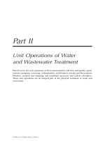
columns and the result of an analysis of a settling test.
At time equals zero, let a particle of diameter d
o
be at the water surface of the
column in a. After time t
o
, let the particle be at the sampling port. Any particle that
arrives at the sampling port at t
o
will be considered removed. In the prototype, this
removal corresponds to the particle being deposited at the bottom of the tank. t
o
is
the detention time. The corresponding settling velocity of the particle is v
o
= Z
o
/t
o
,
where Z
o
is the depth. This Z
o
corresponds to the depth of the settling zone of the
prototype tank. Particles with velocities equal to v
o
are removed, so particles of
velocities equal or greater than v
o
will all be removed. If x
o
is the fraction of all
C
D
v(m/s) R
e
1.0 0.124 95.41
0.90 0.131 100
0.88 0.132 101
FIGURE 5.8 Settling column analysis of discrete settling.
C
D
24
Re
3
Re
0.34 for 1 Re≤ 10
4
≤()++=
C
D
0.4 for Re 10
4
>()=
Re
dv
ρ
µ
dv 997()
9.2 10
4–
()
1,083,695.70dv 769.42v== = =
Water level
Z
o
Z
p
(a) (b)
(c)
Velocity (m/min x 10
-2
)
2.0 3.0
0.16
0.48
0.70
0.85
1.0
0.25
0.35
0.8
0.7
0.6
0.5
0.4
0.4
0.3
0.2
0.1
Weight fraction remaining, x
Sampling
port
TX249_Frame_C05 Page 256 Friday, June 14, 2002 4:27 PM
© 2003 by A. P. Sincero and G. A. Sincero
particles having velocities less than v
o
, 1 − x
o
is the fraction of all particles having
velocities equal to or greater than v
o
. Therefore, the fraction of particles that are
removed with certainty is 1 − x
o
.
During the interval of time t
o
, some of the particles comprising x
o
will be closer
to the sampling port. Thus, some of them will be removed. Let dx be a differential
in x
o
.
Assume that the average velocity of the particles in this differential is v
p
. A
particle is being removed because it travels toward the bottom and, the faster it
travels, the more effectively it will be removed. Thus, removal is directly proportional
to settling velocity. Removal is proportional to velocity, so the removal in dx is
therefore (v
p
/v
o
)dx and the total removal R comprising all of the particles with
velocities equal to or greater than v
o
and all particles with velocities less than v
o
is then
(5.17)
Note that this equation does not state that the velocity v
p
must be terminal. It only
states that the fractional removal R is directly proportional to the settling velocity
v
p
.
For discrete settling, this velocity is the terminal settling velocity. For flocculent
settling (to be discussed later), this velocity would be the average settling velocity
of all particles at any particular instant of time.
To evaluate the integral of Equation (5.17) by numerical integration, set
(5.18)
This equation requires the plot of v
p
versus x. If the original concentration in the
column is [c
o
] and, after a time of settling t, the remaining concentration measured
at the sampling port is [c], the fraction of particles remaining in the water column
adjacent to the port is
(5.19)
Corresponding to this fraction remaining, the average distance traversed by the particles
is Z
p
/2, where Z
p
is the depth to the sample port at time interval t from the initial
location of the particles. The volume corresponding to Z
p
contains all the particles
that settle down toward the sampling port during the time interval t. Therefore, v
p
is
(5.20)
The values x may now be plotted against the values v
p
. From the plot, the numerical
integration may be carried out graphically as shown in c of Figure 5.8.
Example 5.5 A certain municipality in Thailand plans to use the water from the
Chao Praya River as a raw water for a contemplated water treatment plant. The river
is very turbid, so presedimentation is necessary. The result of a column test is as follows:
R 1 x
o
–
v
p
v
o
xd
0
x
0
∫
+=
v
p
v
o
xd
0
x
o
∫
1
v
0
v
p
∆x
∑
=
x
c[]
c
o
[]
=
v
p
Z
p
2t
=
TX249_Frame_C05 Page 257 Friday, June 14, 2002 4:27 PM
© 2003 by A. P. Sincero and G. A. Sincero
What is the percentage removal of particles if the hydraulic loading rate is 25
m
3
/m
2
.
d? The column is 4-m deep.
Solution:
Find the x corresponding to v
o
= 0.0174 m/min
t(min) 0 60 80 100 130 200 240 420
c(mg/L) 299 190 179 169 157 110 79 28
t (min) 0 60 80 100 130 200 240 420
c (mg/L) 299 190 179 169 157 110 79 28
x = [c]/[c
o
] 1.0 0.64 0.60 0.57 0.53 0.37 0.26 0.09
v
p
= Z
p
/2t = 4/2t (m/min) — 0.033 0.025 0.02 0.015 0.01 0.0083 0.0048
t (min) 0 60 80 100 — 130 200 240 420 —
c (mg/L) 299 190 179 169 — 157 110 79 28 —
x = [c]/[c
o
] 1.0 0.64 0.60 0.57 0.55 0.53 0.37 0.26 0.09 0
v
p
= Z
p
/2t
= 4/2t (m/min)
— 0.033 0.025 0.02 0.0174 0.015 0.01 0.0083 0.0048 0
∆x — — — — — 0.02
a
0.16 0.11 0.17 0.09
v
p
in ∆x — — — — — 0.0162
b
0.0125 0.0092 0.0066 0.0024
a
0.02 = 0.55 − 0.53
b
0.0162 =
q
o
hydraulic loading rate 25 m
3
/m
2
d⋅ 25 m/d 0.0174 m/min====
R 1 x
o
v
p
v
o
xd
0
x
o
∫
+–=
v
p
v
o
xd
0
x
o
∫
1
v
o
v
p
∆x
∑
=
v
o
0.0174 m/min=
0.02 0.57
x 0.57–
0.53 0.57–
0.0174 0.02–
0.015 0.02–
=
0.0174 x x 0.55 x
0
==
0.015 0.53
0.0174 0.015+
2
R 1 x
o
1
v
o
Σv
p
∆x+–=
1 0.55–
1
0.0174
[0.0162 0.02()0.0125 0.16()0.0092 0.11()+++=
0.0066 0.17()0.0024 0.09()++]
0.45 0.27+ 0.72 Ans==
TX249_Frame_C05 Page 258 Friday, June 14, 2002 4:27 PM
© 2003 by A. P. Sincero and G. A. Sincero
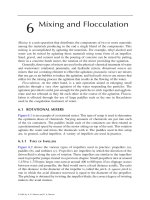
5.2.3 OUTLET CONTROL OF GRIT CHANNELS
Grit channels (or chambers) are examples of units that use the concept of discrete
settling in removing particles. Grit particles are hard fragments of rock, sand, stone,
bone chips, seeds, coffee and tea grounds, and similar particles. In order for these
particles to be successfully removed, the flow-through velocity through the units
must be carefully controlled. Experience has shown that this velocity should be
maintained at around 0.3 m/s. This control is normally carried out using a propor-
tional weir or a Parshall flume. A grit channel is shown in Figure 5.9 and a propor-
tional flow weir is shown in Figure 5.10. A proportional flow weir is just a plate
with a hole shaped as shown in the figure cut through it. This plate would be installed
at the effluent end of the grit channel in Figure 5.9. The Parshall flume was discussed
in Chapter 3.
FIGURE 5.9 A grit channel. (Courtesy of Envirex, Inc.)
FIGURE 5.10 Velocity control of grit channels: (a) proportional-flow weir; (b) cross section
of a parabolic-sectioned grit channel.
Overflow
Maximum
h
t
1
h
1
t
Actual crest
Design crest
Area replacing area cut
off between dotted lines
Theoretical
section
Practical
section
(a) (b)
TX249_Frame_C05 Page 259 Friday, June 14, 2002 4:27 PM
© 2003 by A. P. Sincero and G. A. Sincero
As shown in the figure, the flow area of a proportional-flow weir is an orifice.
From fluid mechanics, the flow Q through an orifice is given by
(5.21)
where K
o
is the orifice constant, ഞ is the width of flow over the weir, and h is the
head over the weir crest. There are several ways that the orifice can be cut through
the plate; one way is to do it such that the flow Q will be linearly proportional to
h. To fulfill this scheme, the equation is revised by letting h
3/2
= h
1/2
h. The revised
equation is
(5.22)
Thus, to be linearly proportional to h, must be a constant. Or,
(5.23)
Equation (5.23) is the equation of the orifice opening of the proportional-flow
weir in Figure 5.10. If the equation is strictly followed, however, the orifice opening
will create two pointed corners that will most likely result in clogging. For this
reason, for values of h less than 2.5 cm, the side curves are terminated vertically to
the weir crest. The area of flow lost by terminating at this point is of no practical
significance; however, if terminated at an h of greater than 2.5 cm, the area lost
should be compensated for by lowering the actual crest below the design crest. This
is indicated in the figure.
The general cross-sectional area of the tank may be represented by kwH, where k
is a constant, w is the width at a particular level corresponding to H, the depth in the
tank. Now, the flow through the tank is Q = v
h
(kwH), where v
h
is the flow-through
velocity to be made constant. This flow is also equal to the flow that passes through
the control device at the end of the tank. The height of the orifice crest from the bottom
of the channel is small, so h may be considered equal to the depth in the tank, H.
From the equation of continuity,
(5.24)
Solving for w,
(5.25)
Therefore, for grit chambers controlled by a proportional-flow weir, the width of
the tank must be constant, which means that the cross-section should be rectangular.
QK
o
ഞh
3/2
=
QK
o
ഞh
1/2
h=
K
o
ഞh
1/2
K
o
ഞ
1
h
1
1/2
K
o
ഞ
2
h
2
1/2
constant ഞh
1/2
⇒ const== =
v
h
kwH()K
o
ഞh
1/2
hK
o
′
ഞh
1/2
H const H()== =
w
const
v
h
k
constant==
TX249_Frame_C05 Page 260 Friday, June 14, 2002 4:27 PM
© 2003 by A. P. Sincero and G. A. Sincero
For grit chambers controlled by other critical-flow devices, such as a Parshall
flume (the proportional flow weir is also a critical-flow device), the flow through
the device is also given by . Thus, the following equation may also
be obtained:
(5.26)
Solving for H,
(5.27)
which is the equation of a parabola. Thus, for grit chambers controlled by Parshall
flumes, the cross-section of flow should be shaped like a parabola. For ease in
construction, the parabola is not strictly followed but approximated. This is indicated
in the upper right-hand drawing of Figure 5.10. The area of the parabola is
(5.28)
Coordinates of the proportional-flow weir orifice. The opening of the weir
orifice needs to be proportioned properly. To accommodate all ranges of flow during
operation, the proportioning should be done for peak flows. For a given inflow peak
flow to the treatment plant, not all channels may be operated at the same time. Thus,
for operating conditions at peak flow, the peak flow that flows through a given grit
channel will vary depending upon the number of channels put in operation. The
proportioning of the orifice opening should be done on the maximum of the peak
flows that flow through the channel.
Let l
mpk
be the l of the orifice opening at the maximum peak flow through the
channel. The corresponding h would be h
mpk
. From Equation (5.23),
and,
(5.29)
Let l
mpk
= w and h
mpk
= Z
ompk
, where Z
ompk
is the maximum depth in the channel
corresponding to the maximum peak flow through the channel, Q
mpk
. Then,
(5.30)
This equation represents the coordinate of the proportional-flow weir orifice.
QK
o
ഞh
3/2
=
v
h
kwH()K
o
ഞh
3/2
K
o
ഞH
3/2
==
H constant w
2
() cw
2
Z
o
===
A
2
3
wH
2
3
wZ
o
==
ഞh
1/2
const l
mpk
h
mpk
1/2
==
h
l
mpk
2
h
mpk
ഞ
=
1
3
h
1
3
w
2
Z
ompk
ഞ
1
9
w
2
Z
ompk
ഞ
==
TX249_Frame_C05 Page 261 Friday, June 14, 2002 4:27 PM
© 2003 by A. P. Sincero and G. A. Sincero
Coordinates of the parabolic cross section. Let A
mpk
be the area in the para-
bolic section corresponding to Q
mpk
. From Equation (5.28),
(5.31)
where w
mpk
is the top width of the parabolic section corresponding Z
ompk
. From
Equation (5.27) and the previous equation, the following equation for c can be
obtained:
(5.32)
From Equation (5.27), again,
(5.33)
Substituting in Equation (5.28),
(5.34)
(5.35)
Thus,
(5.36)
Example 5.6 Design the cross section of a grit removal unit consisting of four
identical channels to remove grit for a peak flow of 80,000 m
3
/d, an average flow
of 50,000 m
3
/d and a minimum flow of 20,000 m
3
/d. There should be a minimum
of three channels operating at any time. Assume a flow-through velocity of 0.3 m/s
and that the channels are to be controlled by Parshall flumes.
Solution: Four baseline cross-sectional areas must be considered and computed
as follows:
A
mpk
2
3
w
mpk
Z
ompk
=
1
3
c
3
2
A
mpk
w
mpk
3
=
Z
o
3
2
A
mpk
w
mpk
3
w
2
=
A
2
3
wZ
o
2
3
w
3
2
A
mpk
w
mpk
3
w
2
w
2
⇒
w
mpk
3
A
mpk
2/3
A
2/3
== =
w
w
mpk
3
A
mpk
1/3
A
1/3
=
Z
o
3
2
A
mpk
w
mpk
3
w
2
3
2
A
mpk
w
mpk
3
w
mpk
3
A
mpk
2/3
A
2/3
3
2
A
mpk
1/3
w
mpk
A
2/3
== =
A
peak, three channels
80,000
3 0.3()24()60()60()
1.03 m
2
A
mpk
===
A
peak, four channels
80,000
4 0.3()24()60()60()
0.77 m
2
==
A
ave
50,000
4 0.3()24()60()60()
0.48 m
2
==
A
min
20,000
4 0.3()24()60()60()
0.19 m
2
==
TX249_Frame_C05 Page 262 Friday, June 14, 2002 4:27 PM
© 2003 by A. P. Sincero and G. A. Sincero
The channels are to be controlled by Parshall flumes, so the cross sections are parabolic. Thus,
and determine coordinates at corresponding areas. Let w
mpk
= 1.5 m.
Note: In practice, these coordinates should be checked against the flow conditions
of the chosen dimensions of the Parshall flume. If the flumes are shown to
be submerged forcing them not to be at critical flows, other coordinates
of the parabolic cross sections must be tried until the flumes show critical
flow conditions or unsubmerged.
Example 5.7 Repeat previous example problem for grit channels controlled
by proportional flow weirs.
Solution: For grit channels controlled by proportional weirs, the cross-section
should be rectangular. Thus,
Therefore, the depths, Z
o
, and other parameters for various flow conditions are as
follows (for a constant flow-through velocity of 0.30 m/s):
Area (m
2
) w(m) Z
o
(m) Q(m
3
/d)
1.03 1.5 1.03 80,000 in three channels
Ans0.77 1.36 0.85 80,000 in three channels
0.48 1.16 0.62 50,000 in four channels
0.19 0.85 0.33 20,000 in four channels
000 0
Z
o
3
2
A
mpk
1/3
w
mpk
A
2/3
=
For A
peak four chambers,
0.77 m
2
:=
Z
o
3
2
A
mpk
1/3
w
mpk
A
2/3
3
2
1.03
1/3
1.5
0.77
2/3
()0.85 m== =
For A
ave
0.48 m
2
:=
Z
o
3
2
A
mpk
1/3
w
mpk
A
2/3
3
2
1.03
1/3
1.5
0.48
2/3
()0.62 m== =
For A
min
0.19 m
2
:=
Z
o
3
2
A
mpk
1/3
w
mpk
A
2/3
3
2
1.03
1/3
1.5
0.19
2/3
()0.33 m== =
w
constant
v
h
k
constant; assume w 1.5 m== =
TX249_Frame_C05 Page 263 Friday, June 14, 2002 4:27 PM
© 2003 by A. P. Sincero and G. A. Sincero
5.2.4 FLOCCULENT SETTLING
Particles settling in a water column may have affinity toward each other and coalesce
to form flocs or aggregates. These larger flocs will now have more weight and settle
faster overtaking the smaller ones, thereby, coalescing and growing still further into
much larger aggregates. The small particle that starts at the surface will end up as
a large particle when it hits the bottom. The velocity of the floc will therefore not
be terminal, but changes as the size changes. Because the particles form into flocs,
this type of settling is called flocculent settling or type 2 settling.
Because the velocity is terminal in the case of type 1 settling, only one sampling
port was provided in performing the settling test. In an attempt to capture the changing
velocity in type 2 settling, oftentimes multiple sampling ports are provided. The
ports closer to the top of the column will capture the slowly moving particles, especially
at the end of the settling test.
For convenience, reproduce the next equation.
(5.37)
As shown in this equation, the fractional removal R is a function of the settling
velocity v
p
. The question is that if the settling is flocculent, what would be the value
of the v
p
? In discrete settling, the velocity is terminal and since the velocity is terminal,
the velocity substituted into the equation is the terminal settling velocity. In the case
of flocculent settling, would the velocity to be substituted also be terminal?
In the derivation of Equation (5.37), however, nothing required that the velocity
be terminal. If the settling is discrete, then it just happens that the velocity obtained
in the settling test approximates a terminal settling velocity, and this is the velocity
that is substituted into the equation. If the settling is flocculent, however, the same
formula of is still the one used to obtain the velocity. Since removal
does not require that the velocity be terminal but simply that removal is proportional
to velocity, this velocity of flocculent settling can be substituted in Equation (5.37)
to calculate the fractional removal, and it follows that the same formula and, thus,
method can be used both in discrete settling as well as in flocculent settling.
Each of the ports in the flocculent settling test will have a corresponding Z
p
.
During the test each of these Z
p
’s will accordingly have corresponding times t and
thus, will produce corresponding average velocities. These velocities and times form
arrays that correspond to each other, including a corresponding array of concentration.
In other words, in the flocculent settling test more test data are obtained. The method
Area(m
2
) w(m) H(m) Q(m
3
//
//
d)
1.03 1.5 0.69 80,000 in three channels
0.77 1.5 0.51 80,000 in four channels
0.48 1.5 0.32 50,000 in four channels
0.19 1.5 0.13 20,000 in four channels
0 1.5 0 0
R 1 x
0
v
p
v
o
xd
0
x
o
∫
+–=
v
p
Z
p
/2t=
TX249_Frame_C05 Page 264 Friday, June 14, 2002 4:27 PM
© 2003 by A. P. Sincero and G. A. Sincero
of calculating the efficiency of removal, however, is the same as in discrete settling
and this is Equation (5.37).
Example 5.8 Assume Anne Arundel County wants to expand its softening
plant. A sample from their existing softening tank is prepared and a settling column
test is performed. The initial solids concentration in the column is 250 mg/L. The
results are as follows:
Calculate the removal efficiency for an overflow rate of 0.16 m
3
/m
2
⋅ min. Assume
the column depth is 4 m.
Solution:
Sampling Time (min)
Z
p
//
//
Z
o
5 10 152025303540
0.1 95
a
68553023———
0.2 129 121 73 67 58 48 43 —
0.3 154 113 92 78 69 60 53 45
a
Values in the table are the results of the test for the suspended
solids (mg/L) concentration at the given depths.
t (min) 0 5 10 15 20 25 30 35 40
Z
p
//
//
Z
o
==
==
0.1
c (mg/L) 250 95 68 55 30 23 — — —
x = [c]/[c
o
] 1.0 0.38 0.27 0.22 0.12 0.092 — — —
v
p
= Z
p
/2t
= 0.1(4)/2t(m/min)
— 0.08
a
0.04 0.03 0.02 0.016 — — —
Z
p
//
//
Z
o
==
==
0.2
c (mg/L) 250 129 121 73 67 58 48 43 —
x = [c]/[c
o
] 1.0 0.52 0.48 0.29 0.27 0.23 0.19 0.17 —
v
p
= Z
p
/2t
= 0.2(4)/2t (m/min)
— 0.16
b
0.08 0.05 0.04 0.032 0.027 0.023 —
Z
p
//
//
Z
o
==
==
0.3
c (mg/L) 250 154 113 92 78 69 60 53 45
x = [c]/[c
o
] 1.0 0.62 0.45 0.37 0.31 0.28 0.24 0.21 0.18
v
p
= Z
p
/2t
= 0.3(4)/2t (m/min)
— 0.24
c
0.12 0.08 0.06 0.048 0.04 0.034 0.03
a
0.08 = 0.1(4)/5
b
0.16 = 0.2(4)/5
c
0.24 = 0.3(4)/5
R 1 x
o
v
p
v
o
xd
0
x
o
∫
+–=
TX249_Frame_C05 Page 265 Friday, June 14, 2002 4:27 PM
© 2003 by A. P. Sincero and G. A. Sincero
It is not necessary to interpolate the x corresponding to v
p
= 0.16 m/min. From the
table, x = x
o
= 0.52.
Therefore,
5.2.5 PRIMARY SETTLING AND WATER-TREATMENT
S
EDIMENTATION BASINS
The primary sedimentation tank used in the treatment of sewage and the sedimen-
tation basin used in the treatment of raw water for drinking purposes are two of the
units in the physical treatment of water and wastewater that use the concept of
flocculent settling. These units are either of circular or rectangular (flow-through)
design; however, they differ in one important respect: the amount of scum produced.
Whereas in water treatment there is practically no scum, in wastewater treatment, a
large amount of scum is produced and an elaborate scum-skimming device is used.
The primary sedimentation basins used in wastewater treatment and water treat-
ment also differ in another respect: the length of detention time. Although longer
detention times tend to effect more solids removal in water treatment, in primary
sedimentation, a longer detention time can cause severe septic conditions. Septicity,
because of formation of gases, makes solids rise resulting in inefficiency of the basin.
Thus, in practice, there is a practical range of values of 1.5 to 2.5 h based on the
average flow for primary settling detention times in wastewater treatment. This range
of figures, although stated in terms of the average, really means that it takes an
average of 1.5 to 2.5 h for a particle of sewage to become septic whether or not the
flow is average.
Both water and wastewater treatment also need to maintain the flow-through
velocity so as not to scour the sludge that has already deposited at the bottom of
the settling tank. They also need properly designed overflow weirs, an example of
which is shown in Figure 5.7b. The particles in both these units are flocculent, so
the flow-through velocity should be maintained at no greater than 9.0 m/h and the
overflow weir loading rate at no greater than 6–8 m
3
/h per meter of weir length, as
mentioned before. Some design criteria for primary sedimentation tanks are shown
in Table 5.2. Except for the detention time, the criteria values may also be used for
settling tanks in water treatment.
v
p
0.24 0.16 0.12 0.08 0.06 0.05 0.048 0.04 0.034 0.032 0.03 0.027 0.023 0.02 0.016 0
x 0.62 0.52 0.45 0.41
a
0.31 0.29 0.28 0.26 0.23 0.21 0.20 0.19 0.17 0.12 0.092 0
∆x — 0.10 0.07 0.04 0.10 0.02 0.01 0.02 0.03 0.02 0.01 0.01 0.02 0.05 0.028 0.092
v
p
in ∆x — 0.20
b
0.14 0.10 0.07 0.055 0.049 0.044 0.037 0.033 0.031 0.029 0.025 0.022 0.018 0.008
a
0.41 = (0.37 + 0.48 + 0.38)/3
b
0.20 = (0.24 + 0.16)/2
R 1 0.52–
1
0.16
[0.14 0.07()0.1 0.04()0.07 0.1()0.055 0.02()++++=
0.049 0.01()0.044 0.02()0.037 0.03()0.033 0.02()0.031 0.01()+++++
0.029+ 0.01()0.025 0.02()0.022 0.05()0.018 0.028()0.008 0.092()]+++ +
0.48 0.178+ 0.66 66%⇒== Ans
TX249_Frame_C05 Page 266 Friday, June 14, 2002 4:27 PM
© 2003 by A. P. Sincero and G. A. Sincero
Design flows to use. When detention time is mentioned, the flow associated
with it is normally the average flow. As noted in Chapter 1, however, sewage flows
are variable. In water treatment, this variation is, of course, not a problem, but it
would be for sewage sedimentation basins. This situation causes a dilemma. A
detention time, although customarily attributed to the average flow, may be attributed
to other flow magnitudes as well. When the detention time to be used is, for example,
2.5 h in order to limit septicity, what is the corresponding flow? In this particular
case, the flow would not necessarily be the average but a flow that would effect a
detention time of 2.5 h. What flow then would effect this detention time?
The settling tank has an inherent capacity to damp out fluctuation in rate of
inflow. In the present example, the flow is being damped out or sustained in a period
of 2.5 h. Because this flow has taken effect during the detention time, it must be the
flow corresponding to this detention time and, hence, must be the one adopted for
design purposes. To size sedimentation basins, the flow to be used should therefore
be the sustained flow corresponding to the detention time chosen. This detention
time must, in turn, be a value that limits septicity. The method of calculating sustained
flows was discussed in Chapter 1.
Suppose a sedimentation basin is to be designed for an average daily flow rate of
0.15 m
3
/s, how would the sustained flow be calculated with this information on the
average flow? It will be remembered that the average daily flow rate is the mean of
all 24-h flow values obtained from an exhaustive length of flow record. The unit to be
designed must meet this average flow requirement, but yet, the actual flow transpiring
inside the tank is not always this average flow. This situation calls for a relationship
between sustained flow and the average flow.
TABLE 5.2
Design Parameters and Criteria for Primary
Sedimentation Basins
Value
Parameter Range Typical
Detention time, h 1.5–2.5 2.0
Overflow rate, m/d 30–50 40
Dimensions, m
Rectangular
Depth 2–6 3.5
Length 15–100 30
Width 3–30 10
Sludge scraper speed, m/min 0.5–1.5 1.0
Circular
Depth 3–5 4.5
Diameter 3–60 30
Bottom slope, mm/m 60–160 80
Sludge scraper speed, rpm 0.02–0.05 0.03
TX249_Frame_C05 Page 267 Friday, June 14, 2002 4:27 PM
© 2003 by A. P. Sincero and G. A. Sincero