Advances in Modern Woven Fabrics Technology Part 2 docx
Bạn đang xem bản rút gọn của tài liệu. Xem và tải ngay bản đầy đủ của tài liệu tại đây (2.95 MB, 20 trang )
Electro-conductive Sensors and Heating Elements Based on
Conductive Polymer Composites in Woven Fabric Structures
9
No. PARAMATER UM VALUE
1 Linear density of the filament g/km 48.23
2 Diameter of the filament mm 0.70
3 Average width of the sensor cross section mm 1.68
4 Average thickness of the sensor cross section mm 1.26
5 Aspect ratio of the sensor (width/thickness) - 1.33
6 Initial resistance of the sensor kΩ 43.3
Table 1. Sensor properties
For insertion in conductive fibre based reinforcements like that woven using carbon
multifilament tows, the sensor was coated with Latex Abformmasse supplied by
VossChemie® so as to insulate the sensor from surrounding carbon tows.
Prepared in this way, the sensor with polyethylene substrate was tested again on MTS 1/2
tester, under quasi static tensile loading at a constant test speed of 5 mm/min. The same
Keithley® KUSB-3100 data acquisition module was employed for the purpose of voltage
variation during tensile testing. This time, a special set-up containing a Wheatstone bridge and
an amplifier was used to measure unknown variable resistance of the sensor as a function of
output voltage. As is obvious from curves presented in Fig. 2-a, b and c, the simple voltage
divider circuit is not adequate for the measurement of resistance change in case of sensors
developed here. These piezoresistive sensors produce a very small percentage change in
resistance in response to physical phenomena such as strain. Moreover the output signal has
considerable noise. Generally, a bridge measures resistance indirectly by comparison with a
similar resistance. Wheatstone bridges offer an attractive solution for sensor applications as
they are capable of measuring small resistance changes accurately (Wilson, 2004).
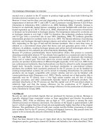
Fig. 4 shows schematic diagram of the data acquisition module developed and used for data
acquisition and its further treatment.
Fig. 4. Schematic of instrumentation amplifier (INA 101) connected to Wheatstone bridge
Advances in Modern Woven Fabrics Technology
10
The resistance variation data thus obtained for different test results was treated for noise
reduction using a low pass filter. The resultant stress-strain-resistance relationship curve up
to 2.75 % elongation of the out of composite sensor (before insertion in the reinforcement) is
shown in Fig. 5.
Fig. 5. Normalized resistance and stress against strain for sensor outside composite
It may be noticed in Fig. 5 that the stress vs. strain curve has the same shape as normalised
resistance (ΔR/R) vs. strain curve. This validates electromechanical properties of our fibrous
sensor for strains ranging from 0 to 2.75 %.
In Fig. 6, the hysteresis results of the sensor for 10 cycles have been given. The sensor
underwent 0.5 % extension at a constant test speed of 5 mm/min, followed by
compression in each cycle. The sensor follows the extension and compression patterns in
each cycle.
The hysteresis is high for the first cycle which reduces gradually and for the 10
th
cycle the
sensor exhibits almost linear behaviour.
2.2 Sensor insertion in carbon woven reinforcement
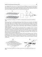
An orthogonal/layer to layer warp interlock with 13 weft layers and 12 warp layers was
chosen as woven structure (Fig. 7-a) and than was woven on a modified conventional loom
(Patronic B60 ARM). 6K multifilament carbon tows (supplied by Hercules Inc.) having 200 tex
was used in both direction – warp and weft. Yarn densities were 24 yarns/cm in warp
direction and 170 yarns/cm in weft direction. The thickness and areal density of resulted
reinforcement were 6.5 mm and 3908 g/m
2
, respectively.
Electro-conductive Sensors and Heating Elements Based on
Conductive Polymer Composites in Woven Fabric Structures
11
Fig. 6. Normalized resistance (ΔR/R) and stress against strain for sensor (Hysteresis 10
cycles at 0.5 % extension)
a) The weave repeat b) The path of the sensor inside woven fabric
Fig. 7. Interlock weave structure used as reinforcement – graphical representation (TexGen
software)
Sensors can be inserted in warp or weft directions during weaving. Given the technical
complications associated with sensor insertion in warp direction during weaving on a loom,
Advances in Modern Woven Fabrics Technology
12
insertion in weft direction has been carried out for preliminary studies. The placement of
sensor in the reinforcement was decided so that the sensor was inserted in the middle of the
structure related to thickness (Fig. 7-b).
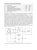
The sensor was inserted during the weaving process, as a weft yarn and it follows the same
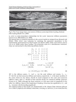
trajectory as the carbon weft yarns inside the reinforcement. In Fig. 8, off the loom dry
reinforcement photograph have been shown. Latex coated sensor connections can be seen
protruding from the reinforcement.
Fig. 8. Reinforcement with protruding sensor connections
2.3 Carbon woven reinforcement impregnation and testing
After weaving, the reinforcement was carefully removed from the loom and was
impregnated using vacuum bag infusion process in order to make the composite part stiff.
The resin employed was epoxy Epolam® 5015. The two connections of the sensor which
remain outside the reinforcement at the two ends were carefully separated from the rest of
the mould. This was done by creating two vacuum sub moulds inside the larger mould so
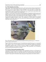
that the resin may not impregnate the two connections of the sensor. The impregnated
composite samples were cut into slabs of 25 X 2.5 cm (Fig. 9).
The composite specimens were tested on Instron 8500 tester. Tensile strength tests were
performed on the composite specimens (according to ISO 527-4, 1997) in the weft direction
i.e., the direction parallel to the inserted sensor. The same Wheatstone bridge was used for
resistance variation measurement. The configuration of the testing equipment was also kept
the same. The composite structural part was tested at constant test speed of 5 mm/min. The
composite underwent traction until rupture.
Electro-conductive Sensors and Heating Elements Based on
Conductive Polymer Composites in Woven Fabric Structures
13
Fig. 9. Textile composite sample containing fibrous piezo-resistive sensor
2.4 On-line measurements of sensor in woven fabric composites - Results
Resultant stress-strain-resistance relationship curve is shown in Fig. 10. It can be observed that
the normalized resistance follows the stress-strain curve. The stress-strain-resistance curve can
be divided into four regions: the initial stiff region - where the composite exhibits toughness
against the applied load represented by high slope; the tows straightening region; the second stiff
region and the zone of rupture. The rupture occurred at the strain of 0.52 %, after which the
tensile strength tester came back to its initial position at the same speed (5 mm/min). Since the
fibrous sensor has not been broken, the normalised resistance (ΔR/R) decreased until zero as
the tester returned to its initial position. However this decrease was not linear because the
sensor was still intact while the resin-sensor interface was partially damaged which caused its
non linear behaviour.
Due to the high difference in yarn densities (24 warp yarns/cm vs. 170 weft yarn/cm), the
weft tows are highly crimped. In the initial stiff region micro-cracks start appearing as the
composite specimen undergoes traction but the interface at resin and multifilament tows is
still intact. That is why the composite exhibits rigid behaviour. In Fig. 10 it can be observed
Advances in Modern Woven Fabrics Technology
14
Fig. 10. Normalized resistance and stress against strain for sensor inside composite
that after the initial stiff region the highly crimped tows tend to straighten due to increasing
tensile load in the second region. In this region the micro-cracks give way to relative
slippage of highly crimped tows in their sockets i.e., the resin-tow interface is relatively
weakened. It can also be remarked that the sensor resistance follows the stress strain curve,
but in the second region the electrical resistance curve is noisier as compared to other
regions of the curve which might signify the slippage of tows as well as the sensor in their
sockets. This second region is followed by the third region called the second stiff region
where the tows are locked in their sockets. In this region the tows resist the applied load and
exhibit stiff behaviour as they regain some of their initial stiffness after the straightening of
tows in the second region. The electrical resistance varies almost linearly with the applied
load, in this region. The third region is followed by the zone of rupture of the composite in
which the electrical resistance, having attained the highest value starts dropping down. The
normalized resistance starts dropping after the rupture. The fact that the sensor resistance
attains its initial value after the rupture signifies that the sensor, owing to its elastic
properties, is not destroyed with the composite. This fact was confirmed by tomographical
image of the samples which underwent traction, shown in Fig. 11-a) and b). Sensor cross
section and its path at and near the zone of rupture can be observed.
In Fig. 11-a) and b) it can be observed that the sensor-resin interface has a lot of voids. These
are caused by poor resin-sensor interfacial properties. The insulating medium on the sensor
surface needs to have good adherence with the epoxy resin and carbon fibre reinforcements.
Damage that occurred at the main rupture zone has propagated along the sensor boundary
giving rise to de-bonding of the sensor. A kink in the sensor can be observed which is
caused by the relaxation of sensor as it tries to regain its original dimensions after the tensile
loading damages the composite sample. The insulation coating around the sensor renders it
thick as well which is undesirable for high performance composite materials as thick
insulation coatings might adversely affect the mechanical properties.
Electro-conductive Sensors and Heating Elements Based on
Conductive Polymer Composites in Woven Fabric Structures
15
a) Frontal view
b) Longitudinal section
Fig. 11. Tomographical images of sensor inside a tested sample near the zone of rupture
3. Heating elements based on conductive polymer composite
The second part of this chapter presents a woven fabric containing an original heating
element. Textile actuators like heating fabrics can find applications in numerous and varied
Advances in Modern Woven Fabrics Technology
16
fields such as sports, leisure, medical and automotive (Droval et al., 2005; El-Tantawy et al.,
2002). In garments, wearability is affected because of the use of metallic components
(heating wire and/or heating track on polymer flexible substrate), that are rarely elastic,
flexible and lightweight. Nevertheless, these metallic, non-textile elements can be replaced
by other conductive fibres such as silver plated polyamide fibres. In that case, the heating
textile becomes lightweight, but very expensive (WarmX GmbH). In all the cases, heating
systems need heavy power supplies. Thus, it is very important to develop heating textile
systems able to work at low voltage.
Our heating element is designed to adapt to woven flexible structures. Additional metallic
yarns, used as electrodes, are integrated in a woven structure (or sewn into textile) in a
comb-teeth arrangement. Function of these electrodes is to connect heating textile to a power
supply and to distribute the current in the conductive coating layer applied on the fabric
surface. The comb-teeth electrode arrangement is specially designed to ensure uniform heat
distribution. The coating is realized with a composite material based on aqueous latex
dispersed with carbon black (CB) as filler. The heating element (comb electrodes and electro-
conductive coating) can thus adopt the desired pattern. This is an important aspect of our
heating element as it allows integration of the heating element in various fabrics designed
for varied and diverse applications.
3.1 Materials and methods
Comb structure was made with stainless steel yarns (2 x 275 x 12 µm from Bekintex®). The
average yarn count was 500 Tex, with a resistivity of 14 ohm/m. These yarns were either
woven or sewn on an existing fabric. The common feature of all the configurations is that
only one comb-teeth structure was used (Fig. 12). The textile fabric was woven on a hand
loom (ARM loom equipped with Selectron command box). A plain weave was chosen.
Cotton yarns were used in warp and weft having densities of 27 and 10 yarns/cm
respectively. The stainless steel yarns were introduced manually during the weaving
process according to the pattern (Fig. 12).
Samples with heating surface (i.e. L x l in Fig. 12) larger than 180 cm² were prepared. In
typical samples, the dimension L was about 140 mm while l was about 150 mm. In this
study, the distance between electrodes (lp) remained unchanged: i.e., 20 mm.
The coating was made using a conductive polymer composite (CPC) composed of carbon
black (CB, Printex ® L6, Degussa), a synthetic rubber latex solution (Kraton® IR-401, Kraton
Polymers) a dispersing agent (Disperbyk®-2010, SPCI) and water.
The preparation procedure is as follows: the dispersing agent is put into water and the CB
particles are gradually added while mixing continuously. The polymer is finally added
while mixing gently in order to avoid too strong shearing. The coating was then applied on
the fabric with a magnetic coating table equipped with a magnetic bar as scraper. 12 samples
were prepared with different CB content: 2.5, 5.0, 7.5, 10.0, 15.0, 20.0, 30.0, 35.0, 40.0, 45.0,
50.0 and 60.0 wt %. These contents were calculated from the total weight CB + Latex
solution. After coating the woven fabric samples were dried at 50 °C for 12 hours. For all the
samples, the thickness of the final coating layer was 450 ± 50 µm.
For each coating surface resistivity was measured using four-point probe (MR-1 Surface
resistance meter, Schuetz Messtechnik). The aim of these measurements is to determine the
percolation threshold and the minimum CB content which allows sufficient electrical
conduction for our application.
Electro-conductive Sensors and Heating Elements Based on
Conductive Polymer Composites in Woven Fabric Structures
17
Fig. 12. General structure (comb-teeth pattern and conductive coating) of heating textile
element
To characterize heating effect of the samples, 2 processes were used:
Feeding of the heating element with variable voltage supply (10, 15, 20 and 24 V). The
surface temperature was recorded using thermocouple at 15 minute intervals at 5
different locations of the fabric. The average temperature was calculated from 5
measurements. Ammeter was used to determine the power consumption (W) of the
heating element. This consumption is expressed in mW/cm² (taking into consideration
the surface area of each sample),
Feeding of the heating element with constant voltage supply (15 V) in conjunction with
an IR camera (Agema ThermoVision 900). This camera took an IR image every 20
seconds.
3.2 Results
Fig. 13 shows electrical resistivity of coatings plotted against filler (CB) content in the latex
solution. As expected, it is possible to identify the percolation threshold from this plot,
which lies at 12 ±1 wt %. The form of the plot is in accordance with the typical behaviour of
systems consisting of percolation networks (Kirkpatrick, 1973).
Advances in Modern Woven Fabrics Technology
18
Fig. 13. Electrical resistivity of the coating vs. CB content in the latex solution
This threshold value in wt % is expressed for liquid latex solution. Liquid latex contains
approximately 63 % of dry material by weight. Thus, the corrected value of percolation
threshold is near 18 wt %. This value is relatively higher than the value reported in
literature for similar systems, (Grunlan et al. 1999, 2001). In our study, process of dispersion
(including rupture of CB aggregate) and coating on fabric is not yet optimized. Obtained
results show that 15 wt % of CB is necessary to obtain à conductive coating. Nevertheless,
Fig. 13 shows that between 15 and 40 wt % resistivity is not optimal: therefore it is
necessary to fill the composite at least by 45 wt % to obtain lower resistivity.
Fig. 14. Surface temperature vs. CB content for feeding voltage of 10, 15, 20 and 24 V
Electro-conductive Sensors and Heating Elements Based on
Conductive Polymer Composites in Woven Fabric Structures
19
Fig. 14 shows surface temperature of coating plotted against the filler content (in liquid
latex) for several feed voltages (10, 15, 20 and 24 V). Temperature on the graph (ΔT) is
expressed as difference between measured temperature and room temperature (between 20
and 22 °C). No elevation of temperature was recorded for sample under 30 wt % of CB. For
CB content between 30 wt % and 45 wt %, ΔT increases with the CB content. Above
45 wt % of CB, ΔT does not increase significantly with filler addition. These results are in
agreement with the previous remarks concerning resistivity vs. CB content.
These results show that the best content of CB was, in our case, 45 wt %. Under this value
heating effect was non optimal. Above this value addition of CB does not increase heating
ability.
Maximum value of ΔT (near 20 K) was registered for sample voltages of 24 V and CB
content of 45 wt % and 60 wt %. Fig. 15 shows that for these heating elements, electrical
input power was close to 250 mW/cm².
Fig. 15. Increase of surface temperature (ΔT) vs. power consumption of heating element
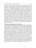
Infrared images show the distribution of heat in the structure (comb electrodes and
conductive coating) vs. time. Fig. 16 shows temperature of sample with 60 wt % of CB from
t = 0 s (Fig. 16-a) to t = 180 s (Fig. 16-f). Feeding voltage was constant and was equal to 15 V.
Fig. 16 shows that comb structure (stainless steel yarn) heats first after switching on. The
maximum temperature of this yarn was about 70 °C. This temperature is achieved after 120
s. CB coating heats relatively slowly but it can be conjectured that after 120 s the
temperature of all the surface area exceeds 35 °C while it exceeds 40 °C after 180s. This
behaviour is expected since stainless steel yarns have better thermal conductivity than
carbon based composite.
4. Conclusion
The sensor based on conductive polymer composite, developed for in situ measurements on
carbon fibre based woven fabric composite, is capable of detecting strain in the structure.
The electrical resistance variation in the sensor follows the deformation pattern of the
composite, mainly due to its sensitivity to its environment and because of the fact that it is
Advances in Modern Woven Fabrics Technology
20
a) t = 0 s
b) t = 20 s
c) t = 40 s d) t = 60 s
e) t = 120 s
f) t = 180 s
Fig. 16. IR image of 60 wt % CB heating element from a) t = 0 s to f) t = 180 s, voltage = 15V
integrated in the structure and follows the fibre architecture of the reinforcement. It has
been shown that the integrated textile sensors inside the reinforcement can be used as in situ
strain gages for the composite materials. Moreover, if the placement of these sensors inside
the reinforcement is carefully chosen, they can be used to follow the local deformation
pattern so as to better understand the deformation mechanisms and predict life time of the
composite parts. At present the sensors have been tested for tensile loading. Tensile strength
tests were chosen to demonstrate the basic features of this novel SHM approach. In the
future these sensors will be used for bending and fatigue tests on similar 3D carbon fibre
woven reinforcement based composites. However optimisation of sensors needs to carried
out in order to prepare finer sensors having negligible affect on reinforcement geometrical
and mechanical properties. For carbon fibre based reinforcements which require an
insulation coating on the sensor surface, a better and finer coating needs to be applied. In
view of the test results presented, it can be concluded that these sensors can be used for in
situ health monitoring of various types of composites for industrial applications
(aeronautics, automotive etc).
We have also developed a heating element based on original comb-teeth structure (stainless
steel electrode) and electro-conductive coating composed of latex and carbon black. Comb
structure can be either woven or sewn into the fabric. Final product is flexible and
lightweight. This study has show that ideal carbon content of the coating was 45 wt % in a
latex solution. Our heating elements (about 200 cm²) allow increasing the temperature (ΔT)
by 20 K with low voltages (between 15 and 24 V). Temperature homogeneity of heating
Electro-conductive Sensors and Heating Elements Based on
Conductive Polymer Composites in Woven Fabric Structures
21
elements is better than those of heating elements made with only stainless steel yarns
because in the later case, heat is only produced and localized at conductive yarns. Moreover,
our system is cost efficient because we used a few stainless steel yarns.
The next step of this study would allow, in the first place, the optimization of composite
preparation (liquid Latex + CB) and secondly the realization of larger heating elements (>
0.5 m²). Potential applications of these heating elements can be found in garments (to
improve thermal comfort), in transportation where heating is required for passenger
comfort and in certain industrial systems (antifreeze).
5. Acknowledgements
This research was partially financed by Interreg IV via TRITEX (Transfer of Research and
Innovations in TEXtiles) program (FLV1.1.1). Special acknowledgments to Textile
Department Laboratory from UGENT (Belgium) for electrical measurements (part 3.) and
use of IR camera.
6. References
Black, S. (2009). Structural health monitoring: Composites get smart, Composites World,
/>composites-get-smart
Cochrane, C., Koncar, V., Lewandowski, M., & Dufour, C. (2007). Design and development
of a flexible strain sensor for textile structures based on a conductive polymer
composite. Sensors, Vol. 7, pp. 473-492.
Cochrane, C., Lewandowski, M., & Koncar, V. (2010). A Flexible Strain Sensor Based on a
Conductive Polymer Composite for in situ Measurement of Parachute Canopy
Deformation. Sensors, Vol. 10, pp. 8291-8303.
Dharap, P., Zhiling L., Nagarajaiah, S. & Barrera, E.V. (2004). Nanotube film based on single-
wall carbon nanotubes for strain sensing, Nanotechnology, vol. 15, pp. 379-382.
Droval, G., Glouannec, P., Feller, J.F., & Salagnac, P. (2005). Simulation of electrical and
thermal behavior of conductive polymer composites heating elements. Journal of
Thermophysics, Vol. 19, No. 3, pp. 375-381.
El-Tantawy, F., Kamada, K., & Ohnabe, H. (2002). In situ network structure, electrical and
thermal properties of conductive epoxy resin–carbon black composites for electrical
heater applications. Materials Letters, Vol. 56, pp. 112-126.
European Standard NF EN ISO 527-4 (1997), Plastiques - Détermination des propriétés en
traction, Partie 4 : Conditions d´essai pour les composites plastiques renforcés de
fibres isotropes et orthotropes.
Fiedler, B., Gojny, F. H., Wichmann, M. H. G, Bauhofer, W. & Schulte, K. (2004). Can carbon
nanotubes be used to sense damage in composites?, Annales de chimie, 29, p. 81-94.
Gettinger, C.L., Heeger, A.J., Pine, D.J. & Cao, Y. (1995). Solution characterization of
surfactant solubilized polyaniline. Synth. Met., 74, pp. 81-88.
Grunlan, J., Gerberich, W., & Francis, L. (2001). Lowering the percolation threshold of
conductive composites using particulate polymer microstructure. Journal of
applied polymer science, Vol. 80, No. 4, pp. 692-705.
Advances in Modern Woven Fabrics Technology
22
Grunlan, J., Gerberich, W., & Francis, L. (1999). Electrical and mechanical property
transitions in carbon-filled poly(vinylpyrrolidone). Journal of materials research,
Vol. 14, No. 11, pp. 4132-4135.
Haba, Y., Segal, E., Narkis, M., Titelman, G.I. & Siegmann, A. (1999). Polymerization of
aniline in the presence of DBSA in an aqueous dispersion. Synth. Met., 106, 59-66.
Heeger, A.J. (2002). Semiconducting and metallic polymers: the fourth generation of
polymeric materials. Synth. Met. No. 125, pp. 23-42.
Kamiya, R., Cheeseman, B. A., Popper, P. & Chou, T W. (2000). Some recent advances in the
fabrication and design of three-dimensional textile preforms: a review. Composites
Science and Technology, Vol. 60, pp. 33-47.
Kirkpatrick, S. (1973). Percolation and conduction. Reviews of Modern Physics, Vol. 45, No.
4, pp. 574-588.
Ko, F. (2007). 3-D textile reinforcements in composite materials, 3-D Textile Reinforcements
In Composite Materials. vol. null: Woodhead Publishing Limited.
Krupa, I. & Chodak, I. (2001). Physical properties of thermoplastic/graphite composites.
Europ Polym J., 37, pp. 2159-2168.
Kumar, D., & Sharma, R.C. (1998). Advances in conductive polymers. Eur. Polym. J. No. 34,
pp. 1053-1060.
Li, C., Thostenson, E. T. & Chou, T. W. (2008). Sensors and actuators based on carbon
nanotubes and their composites: A review, Composites Science and Technology,
vol. 68, pp. 1227-1249.
Lorussi, F., Scilingo, E. P., Tesconi, M., Tognetti, A. & De Dossi, D. (2005). Strain sensing
fabric for hand posture and gesture monitoring, IEEE Transactions On Information
Technology In Biomedicine, vol. 9, pp. 372-381.
Novak, I., Krupa, I. & Chodak, I. (2002). Investigation of the correlation between electrical
conductivity and elongation at break in polyurethane-based adhesives. Synth. Met.,
131, 93–98.
Scilingo, E. P., Lorussi, F., Mazzoldi, A. & De Rossi, D. (2003). Strain-sensing fabrics for
wearable kinaesthetic-like systems, IEEE sensors journal, vol. 3, pp. 460-467.
Wilson, J. (2004). Sensor signal conditioning, Sensor Technology Handbook. vol. null:
Newnes Publishing Limited.
www.nottingham.ac.uk/~emxmns/texgen.htm, consulted on 10/01/2011
www.datasheetdir.com/INA101-Instrumentation-Amplifiers, consulted on 06/05/2010.
2
Smart Woven Fabrics in Renewable
Energy Generation
Derman Vatansever, Elias Siores, Ravi L. Hadimani and Tahir Shah
University of Bolton, Institute for Materials Research and Innovation
United Kingdom
1. Introduction
Initially, the first purpose of fabric making was only for covering the body and sheltering.
However, with a growing population and ever improving advanced technologies, today’s
fabrics are mostly used for fashion and performance thus enhancing the standard of
people’s everyday life and enjoyment.
Most of the technologies which increase the standard of living also increase carbon emission
and adversely affect human life indirectly. Warming buildings, using cars, provide hot
water, cooking food etc. need energy generated by using coal, gas, fuel or electricity.
Burning gas and fuel accelerate the threat of nature and eventually contribute to global
warming. Even electricity generation causes carbon emission unless it is generated by using
renewable energy sources. Interest in providing renewable usable electrical power from the
environment has grown, particularly in the elimination of battery usage, because of their
sizeable dimensions, weight and limited lifetime.
Since global warming is being considered as the biggest danger for the nature, many
scientists and researchers have brought a new breath to their researches. As almost all areas
of renewable science and technology, researchers are now working in the field of textile
fabrics capable of generating green electricity.
Undoubtedly, weaving is the oldest fabric making method which has been a part of human
life for protection from nature’s elements and hazards. It is now possible to produce smart
woven fabrics by combining the oldest fabric making method with smart fibre material
technologies. The chapter named “Smart Woven Fabrics in Renewable Energy Generation“
contains a brief introduction to smart materials, focusing on piezoelectricity and polymer
based piezoelectric fibre production. The rest of the chapter explains how to produce smart
woven structures by integrating smart fibres into the fabric during weaving process and
examples for possible applications for energy regeneration from nature’s elements are given.
2. Brief introduction to weaving and looms
2.1 Vertical and horizontal looms
The first loom consisted of only a branch of a tree that is parallel to the ground. In this
simple design, warp threads were directly fastened to the branch of a tree and held parallel
to each other under tension caused by tied stones at the other end of the warps. The weft
threads work from right to left and left to right by passing through hanging warps until the
Advances in Modern Woven Fabrics Technology
24
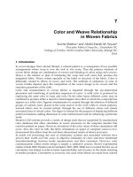
Fig. 1. (a) A vertical warp-weighted loom used in Iceland, reconstructed and set up before
1914, National Museum of Iceland-Photograph by Gilsli Gestsson (Broudy, 1979),
(b) a horizontal ground loom used in Northen Cameroon-Photograpgh by René Gardi
(Broudy, 1979).
Fig. 1. (c) An example of laboratory scale hand looms and (d) an example of automated
looms (wikipedia, 2011).
Smart Woven Fabrics in Renewable Energy Generation
25
designed fabric is composed. Later, a simple framework was made of tree branches to form
a vertical loom to use for indoor as well as outdoor.
Figure 1 (a and b) show examples for early vertical loom and horizontal looms and Figure 1
shows a laboratory scale hand loom (c) and automated loom (d). Warp threads are attached
to heddles and held parallel to each other on the loom and weft thread is held by a shuttle.
The heddles keep warp threads apart so that the shuttle could pass through easily and cary
the thread from left to right and right to left so that the weft will work over and under warp
threads to form a fabric. Movements of the heddles on hand looms are controlled by pedals
beneath the loom.
Current generation looms (Fig. 1d) are fully automated. Movements of the heddles are
automatically controlled according to the fabric design sent via a computing system. The
important parameters, such as tension, speed, temperature etc., are measured and/or
controlled by the controlling systems. Thus, any errors that occur during the fabric
production are immediately detected.
2.2 Main weaving constructions
Weaving is one of the traditional fabric making methods. There are two sets of threads,
warp threads and weft threads which form a fabric by being interlaced row by row.
Weaving has three main construction techniques; plain weaving, twill weaving and satin
weaving. Any other techniques developed are variations of these main techniques.
Plain weave is created by interlacing the weft across the warp threads and for this at least 2
heddles are needed. Weft thread goes under a warp thread and then over the next one so
that the equal amount of weft and warp is seen on both surfaces of the woven fabric.
Twill weave is created by interlacing two or more weft threads over and under one or
more warp threads so that at least three heedles are needed to make a twill woven fabric.
In twill wovens, parallel diagonal ribs are formed from left to right or from right to left
that depends on the formation, woven fabric is characterised and named as “S“ or “Z“
twill, respectively. If a twill woven has more warps than the wefts on the fabric face is
known as warp faced twill and if it has more wefts on the fabric face, it is known as weft
faced twill.
Satin weave is created by floating four or more yarns before a single interlacing occurs and
at least 5 heddles are needed to make a satin woven fabric. The warp or weft threads pass
across many threads in such a way, like 4/1, 5/1, 7/1 etc., that the face of the woven fabric
is mostly covered with either warp or weft threads and known as warp satin or weft satin,
respectively.
Depending on the construction of the weave and characteristics of the used warp and weft
threads, fabric properties may vary. Count of the used fibres/yarns determines the fabric
density which affects the weight, feel, appearance, thickness etc. Variable properties are
many and can be found in the literature (Gioello, 1982). They include:
Weight
Hand and feel
Drapeability
Appearance
Covering power
Surface texture
Body fit
Advances in Modern Woven Fabrics Technology
26
Thickness
Lustre
Strength
Flexibility / pliability
Resiliency
Warmth
Affinity to dyestuff
Fabrics created by using plain weave technique are tough compared to twill and satin
weave. The fabrics made by twill weaving technique are more pliable and drapable than
plain weave fabrics but not as pliable as satin weave. However, strength of plain woven
fabrics is higher than both twill and satin woven fabrics.
3. Smart materials and piezoelectricity
A smart material is one that shows extraordinary response when subjected to a stimulus.
Piezoelectric materials are considered as smart materials because of their ability to generate
electricity against the stimulus which is mechanical strain or vibration (Fig.2a). This
property of piezoelectric materials is known as direct piezoelectric effect. The reverse effect
is also possible in that this material undergoes a slight deformation in shape when a small
electrical field is applied (Fig.2b).
Fig. 2. (a) Direct piezoelectric effect; mechanical energy is converted to form electrical
energy, (b) Converse piezoelectric effect; electrical energy causes deformation in the shape
of piezoelectric material.
Direct piezoelectric effect of the materials is also known as “generator effect“ or “sensor
effect“. The terms “motor effect“ and “actuator effect“ are also used to mean converse
piezoelectric effect of the piezoelectric material. It should also be pointed out that the
piezoelectric effect can be induced when heat or cooling is involved, in which case this
phenomenon is termed thermoelectric or pyroelectric effect.
Smart Woven Fabrics in Renewable Energy Generation
27
Direct piezoelectric effect is mainly used for energy harvesting. The term “Energy
Harvesting” is used to describe the process of extracting energy from the environment and
the extracted energy is converted and stored in the form of electrical energy.
Although energy harvesting technologies have been known for many years, increasing
concern about global warming has led to intensive research for alternative energy sources
including piezoelectrics. With an increasing concern about global warming, piezoelectricity
has gained a significant importance and intensive research and development efforts are
being made for extracting energy from the environment [Umeda et al., 1997; Sodano et al.,
2004; Mateu & Moll, 2005].
Fig. 3. Defining the modes of piezoelectric material
The generated electrical charge of a piezoelectric material under a mechanical stress can be
formulated in terms of dielectric displacement, D (charge per unit area, C/m
2
) [Schwartz,
2002; Granstrom et al., 2007; Swallow et al., 2008]
iijj
Dd (1)
where “d
ij
“ is the piezoelectric charge coefficient (C/N) and “σ
j
“ is the stress (N/m
2
). “i“ is
the direction of polarization and takes terms 1–3 and “j“ is the direction of applied stress
having subscripts 1–6 (Fig. 3).
In Figure 3, numbers 1, 2 and 3 present x,y and z axes of piezoelectric material, respectively.
Modes 31 and 33 are two coupling modes of piezoelectric materials that when a force is
applied in the perpendicular direction to the poling direction, the piezoelectric voltage
coefficient acts in the mode 31. When a force is applied in the parallel direction to the poling
direction, the piezoelectric voltage coefficient acts in the mode 33 which generally yields a
higher coupling coefficient (k) [Roundy et al., 2005; Baker et al., 2007; Anton & Sodano 2007;
Patel et al., 2010] which is the ability of piezoelectric materials to convert mechanical energy
into electrical energy and vice versa, and can be defined by,
Advances in Modern Woven Fabrics Technology
28
k
Y
d (2)
where “ε” is dielectric constant and “Y” the elastic modulus of the material.
Piezoelectric voltage coefficient (g) relating the electric field generated by an applied
mechanical stress and relationship between the piezoelectric charge coefficient and
piezoelectric voltage coefficient can be expressed as [Jordan & Ounaies, 2001],
0
/K
j
gij dij (3)
where; “
0
” is the permittivity of free space (8.85x10⁻¹² F/m) and “Kj” is the relative
dielectric constant of the material.
Since the discovery of piezoelectricity in ceramics [Shirane & Suzuki, 1952; Jaffe et al.,
1971] and polymers [Kawai, 1969], various studies have been carried out on structural
changes [Ramos et al., 2005; Sencadas 2006], poling [Seo et al., 1985; Holstein et al., 1999;
Neagu et al., 1999; Parvanova & Nadoliisky 2005] and applications, such as sensors [Tzou
& Tseng 1990; Sirohi & Chopra 2000], actuators [Baz & Poh 1988; Schmidt et al., 2006],
energy harvesting [Sodano & Inman 2004; Shu & Lien 2006; Granstrom et al., 2007;
Ramadass & Chandrakasan 2010] and so on. PZT has been pre-eminent due to its
piezoelectricity among other piezoelectric materials, with a piezoelectric coefficient (d
33
)
of 220pC/N [Hellwege, 1996] while PVDF exhibits much lower piezoelectric coefficient of
d
33
≈ 35pC/N [Sencadas et al., 2006; De-Qing, 2008; Jain et al., 2010; Patel et al., 2010].
However, flexible nature of polymers adds extra versatility for applications against
ceramic based piezoelectric materials.
With the invention of new polymers exhibiting piezoelectric and better mechanical
properties, the scope of application has widened. Both ceramic and polymer based
piezoelectric materials have found a wide range of application in many areas. Ceramic
based piezoelectric materials, in general, have a higher piezoelectric constant compared to
polymer based piezoelectric materials. However, polymer based piezoelectric materials
have an advantage of being flexible which makes them preferable for many applications,
particularly for wearable applications. This flexibility can also result in better conversion of
energy in certain applications.
3.1 Flexible piezoelectric fibres
There are many naturally occurring piezoelectric structures, such as cane sugar, tendon, silk,
bones etc., but polymers are not natural piezoelectric materials. However, polymers such as
polyvinylidene fluoride (PVDF), polyproplylene (PP), polyethylene terephthalate (PET), odd
numbered polyamides (PA11, PA9, PA7, PA5) etc. can be made piezoelectric (Kawai, 1969;
Newman et al. 1980; Dunn & Carr, 1988; Harrison & Ounaies, 2001).
Siores et al (2010) were the first to develop and patent a continuous process for making
piezoelectric fibres by extruding suitable polymers. To produce piezoelectric PVDF fibres
via a continuous process on the melt extruder, granular PVDF was fed to extruder screw
which was heated above melting point of the polymer. To gain the piezoelectricity,
molecular chain of the PVDF fibre must be re-oriented and transformed from non-
piezoelectric α-phase to piezoelectric β-phase by applying a high stretching ratio (Sencadas
et al., 2006), heat (Neagu et al., 1999) at the stretching region and high voltage (Holstein et
al., 1999 & Ramos et al., 2005), simultaneously.