Advances in Satellite Communications Part 3 doc
Bạn đang xem bản rút gọn của tài liệu. Xem và tải ngay bản đầy đủ của tài liệu tại đây (1.13 MB, 15 trang )
Helical Antennas in Satellite Radio Channel
19
a)
b)
Fig. 11. a) Standard, conical and tapered BHAs, and b) their radiation patterns.
F/B (dB) Gain (dB) AR HPBW (°)
Standard BHA 4.5 5.6 0.79 111
Conical BHA 15.6 6.5 0.92 113
Tapered BHA 16 7.6 0.76 87
Table 1. Simulation results of radiation characteristics of standard, conical and tapered BHA.
F/B (dB) Gain (dB) AR HPBW (°)
Tapered BHA
(n
t
= 1.5, n
u
=3)
15.4 7.1 0.72 90
Tapered BHA
(n
t
= 0.8, n
u
= 3)
11.2 5.7 0.89 120
Tapered BHA
(n
u
= 0, n
t
= 2.3)
7.5 6 0.72 85
Tapered BHA
(n
u
= 1, n
t
= 2.3)
14.8 7.8 0.65 82
Tapered BHA
(n
u
= 2, n
t
= 2.3)
14.0 7.8 0.75 87
Table 2. Simulation results of reduced size tapered BHA.
Advances in Satellite Communications
20
a)
b)
Fig. 12. Geometry and radiation patterns of reduced size BHA, a) and b) respectively.
a) b)
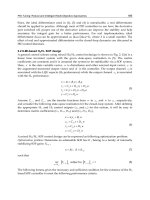
Fig. 13. Typical radiation patterns of bifilar scanning helical antenna, a) conical at 1.6 GHz
and b) normal radiation pattern at 2.1 GHz.
Contrary to monofilar helical antenna, the bifilar helical antenna yields scanning radiation
mode when relative phase velocity p = v/c = 1.0. This is confirmed with the comparison
of the simulated results with the experimental and calculated results (Nakano et al.,
1991; Zimmerman, 2000) of the lobe direction for the different values of phase velocity,
Fig. 14.
Helical Antennas in Satellite Radio Channel
21
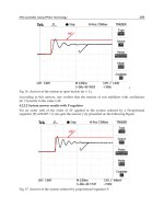
1.4 1.6 1.8 2 2.2 2.4
70
80
90
100
110
120
130
140
150
Frequency (GHz)
Lobe direction in degrees
experimental (Nakano et al., 1991) and calculated results for p = 1.0 (Zimmerman, 2000)
calculated results for p = 0.9 (Zimmerman, 2000)
FEKO simulations
Fig. 14. The comparison of the simulated, calculated and experimental results for the lobe
direction vs. frequency.
3.2 The quadrifilar helical antenna
The quadrifilar helical antenna (QHA), also known as the Kilgus coil, is mostly used for
telemetry, tracking and command (TT&C) satellite systems due to its simplicity, small size,
wide circularly polarized beam and insensitivity to nearby metal objects. The QHA consists
of four helical wires equally spaced circumferentially and fed from the top or the bottom.
The open ended QHA generally uses the length of each wire of
λ
/4 or 3
λ
/4 with typical
input impedance in the range 10 to 20 ohms while the short–circuited QHA uses
λ
/2 or
λ
length of each wire which produces resonant input impedance of nearly 50 ohms. Printed
QHAs, convenient for high frequency applications, are manufactured using the dielectric
substrate (Chew et al., 2002; Hanane et al., 2007) while wire QHA-s can be implemented on
cylindrical, conical, square and spherical dielectric mechanical supports (Casey & Bansal,
2002; Hui et al., 2001). The size reduction of quadrifilar helical antennas can be achieved
with geometrical reduction techniques such as sinusoidal (Fonseca et al., 2009; Takacs et al.,
2010), rectangular (Ibambe et al., 2007), meander line (Chew et al., 2002) and other
techniques (Letestu et al., 2006).
Radiation pattern of fractional turn resonant QHA is cardioid-shaped and circularly
polarized with wide beamwitdh, but by extending the fractional-turn QHA to an integral
number of turns shaped-conical radiation pattern can be obtained for many applications in
spacecraft communications (Kilgus, 1975).
The Kilgus coil consisted of four wires
λ
/2 long and forming a ½ turn of a helix, generates a
cardioid-shaped backfire radiation pattern with circular polarization and a very high HPBW
Advances in Satellite Communications
22
when two pairs are fed in phase quadrature and lower ends are short-circuited (Kilgus,
1968, 1974). The antenna is fed with a split sheath balun and the phase quadrature is
achieved by adjusting the lengths of the wires.
The performance of the QHA is described with the following parameters: the length of one
element consisted of two radials and a helical section l
el
(integer number of
λ
/2), axial length
between the radials l
ax
and the number of turns N. We designed a half turn QHA for GPS L2
signal with the central frequency of f = 1220 MHz and the following parameters: l
el
=
λ
/2,
wire diameter d = 2 mm, bending radius b
r
= 5 mm and width-to height ratio w/h = 0.44 (the
length of wires was adjusted to achieve phase quadrature so width w is the longitudinal
width and h is axial height (l
ax
) of the antenna). This is the so called self-phased QHA where
the wire of one bifilar helix is longer than the resonant length, so that the current has a phase
lead of 45° and the other is shorter in order to achieve a phase lag of 45°. Instead of infinite
balun, we proposed a stripline structure for impedance matching and the support for helical
wire. Fig. 15 c) shows that matching stripline is made of shorter part designed to counteract
the imaginary part of the antenna input impedance and longer quarterwave part which is
used to tune the real component of antenna input impedance to 50-Ω coaxial line impedance
(Sekelja et al., 2009).
a) b) c)
Fig. 15. The geometry with wire segments a) and simulated radiation patterns b) of QHA
and c) the antenna prototype with stripline feeding structure.
In many satellite applications, it is also desirable to concentrate the radiated energy into a
shaped conical beam with full cone angles from 120° to 180° (Kilgus, 1975). So, for the same
frequency, f = 1220 MHz, we simulated a three turn QHA (Fig. 16 a)) fed in phase
quadrature with short circuited ends which achieves gain decreasing from the maximum of
5.6 dB at the edge of the cone to the local minimum of -2.5 dB at the centre. Radiation
pattern in Fig. 16 b) also shows that this antenna gives an excellent axial ratio.
Helical Antennas in Satellite Radio Channel
23
a) b) c)
Fig. 16. a) The geometry, b) the 2D and c) 3D simulated radiation patterns of three turn
QHA.
5. Conclusion
In this chapter, the basic theory and simulations of helical antennas are presented. It is
shown that various radiation patterns can be obtained with conventional helical antenna
and its modifications: forward and backward radiation, beam, normal and scanning
radiation, from hemispherical to conical-shaped radiation patterns. The circular polarization
is easily achieved (except for the normal mode) and it can be improved by end tapering.
These modifications include the change of helix geometry, the size and shape of reflector,
the number of wires and implementing some guiding structure.
However, when implementing real materials in practical design, they must be evaluated for
their influence on the overall antenna performance. Thus, while the depicted analytical
approach offers a tool for the optimal design and basic analysis of the helical antenna,
although not completely impossible, it becomes too complex to be implemented in final
decision about the practical design. The performances of the designed antenna must
therefore be tested by some numerical tool or by measurements.
6. References
Adekola, A. S., Mowete, A. I. & Ayorinde, A. A. (2009). Compact theory of the broadband
elliptical helical antenna, European Journal of Scientific research, Vol. 31, No. 3, (2009),
pp. 446-490, ISSN 1450-216X
Amin, M., Cahill, R. & Fusco, V. Single feed low profile omnidirectional antenna with slant
45° linear polarization, IEEE Transactions on Antennas and Propagation, Vol. 55, No.
11, (November 2007), pp. 3087-3090, ISSN 0018-926X
Barts, R. M. & Stutzman, W. L. (1997). A reduced size helical antenna, Proceedings of IEEE
Antennas and Propagation Society International Symposium, ISBN 0-7803-4178-3,
Montreal, Canada, July 1997.
Advances in Satellite Communications
24
Blazevic, Z. & Skiljo, M. (2010). Bandwidth of the Helical Beam Antenna Loaded by a
Dielectric Rod, Proceedings of ICECom, ISBN 978-1-61284-998-0, Dubrovnik, Croatia,
September 2010.
Bulgakov, B. M., Shestopalov, V. P., Shiskin, L. A. & Yakimenko, I. P. (1960). Symmetrical
surface waves in a helix waveguide with a ferrite medium, Journal of Radio and
Electronic Physics, Vol. 5, No. 11, (1960), pp. 102-119
Carver, K. R. (1967). The helicone-a circularly polarized antenna with low side-lobe level,
Proceedings of the IEEE, Vol. 55, No. 4, (April 1967), p. 559, ISSN 0018-9219
Casey, J. P. & Basal, R. (1988). Dielectrically loaded wire antennas, Proceedings of the IEEE,
Vol. 135, No. 2, (April 1988), pp. 103-110, ISSN 0950-107X
Casey, J. P. & Basal, R. (1988) Square helical antenna with a dielectric core, IEEE Transactions
on Electromagnetic Compatibility, Vol. 30, No. 4, (November 1988), pp. 429-436, ISSN
0018-9375
Cha, A. G. (1972). Wave propagation on helical antennas, IEEE Transactions on Antennas and
Propagation, Vol. 20, No. 5, (September 1972), pp. 556-560, ISSN 0018-926X
Chew, D. K. C. & Saunders, S. R. (2002). Meander line technique for size reduction of
quadrifilar helix antenna, IEEE Antennas and Wireless Propagation Letters, Vol. 1, No.
1, (2002.) pp. 109-111, ISSN 1536-1225
Djordjevic, A. R., Zajic, A. G. & Ilic, M. M. (2006). Enhancing the gain of helical antennas by
shaping the ground conductor, IEEE Antennas and Wireless Propagation Letters, Vol.
5, No. 1, (December 2006), pp. 138-140, ISSN 1536-1225
Fonseca, N. J. G. & Aubert, H. (2009). Very compact quadrifilar helix antenna in VHF band
with quasi hemispherical radiation pattern, Proceedings of IEEE Antennas and
Propagation Society International Symposium, ISBN 978-1-4244-3647-7, Charleston,
South Carolina, June 2009.
Hanane, L., Hebib, S., Aubert, H. & Fonseca, N. J. G. (2007). Compact printed quadrifilar
helix antennas for stratospheric ballons telemetry, Proceedings of IEEE Antennas and
Propagation Society International Symposium, ISBN 978-1-4244-0877-1, Honolulu,
Hawai, June 2007.
Hui, H. T., Yung, E. K. N. & Leung, K. W. (1997). Numerical and experimental studies of a
helical antenna loaded by a dielectric resonator, Radio Science, Vol. 32, No. 2,
(March-April 1997), pp. 295-304, ISSN 0048-6604
Hui, H. T., Chan, K. Y. & Yung, E. K. N. (2001). The input impedance and the antenna gain
of the spherical helical antenna, IEEE Transactions on Antennas and Propagation, Vol.
49, No. 8, (August 2001), pp. 1235-1237, ISSN 0018-926X
Ibambe, M. G., Letestu, Y. & Sharaiha, A. (2007). Compact printed quadrifilar helical
antenna. Electronic Letters, Vol. 43, No. 13, (June 2007), pp. 697-698, ISSN 0013-5194
Kilgus, C. (1968). Multielement, Fractional Turn Helices. IEEE Transactions on Antennas and
Propagation, Vol.16, No.4, (July 1968), pp. 499-500 , ISSN 0018-926X
Kilgus, C. (1974). Spacecraft and Ground Station Applications of the Resonant Quadrifilar
Helix, Proceedings of IEEE Antennas and Propagation Society International Symposium,
Vol.12, pp. 75-77, June 1974.
Kilgus, C. (1975). Shaped-Conical Radiation Pattern Performance of the Backfire Quadrifilar
Helix. IEEE Transactions on Antennas and Propagation, Vol. 23, No. 3, (May 1975), pp.
392-397 , ISSN 0018-926X
Helical Antennas in Satellite Radio Channel
25
Klock, P. (1963). A study of wave propagation of helices, University of Illinois Antenna
Laboratory Technical Report No. 68, March 1963.
Kraft, U. R. & Mönich, G. (1990). Main-beam polarization properties of modified helical
antennas, IEEE Transactions on Antennas and Propagation, Vol. 38, No. 5, (May 1990),
pp. 589-597, ISSN 0950-107X
Kraus, J. D. & Williamson J. C. (1948). Characteristic of helical antennas radiating in the axial
mode, Journal of Applied Physics, Vol. 19, No. 1, (January 1948), pp. 87-96, ISSN 0021-
8979
Kraus, J. D. (1949). The helical antenna, Proceedings of IRE, Vol. 37, No. 3, (March 1949), pp.
263-272, ISSN 0096-8390
Kraus, J. D. (1988). Antennas (2
nd
ed), McGraw-Hill Companies, ISBN 978-0070354227, New
Delhi, India
Lan, C. W., Chang, T. H. & Kiang, J. F. (2004). Helical antenna for GPS applications,
Proceedings of IEEE Antennas and Propagation Society International Symposium, ISBN 0-
7803-8302-8, June 2004.
Letestu, Y. & Sharaiha, A. (2006). Broadband folded printed quadrifilar helical antenna, IEEE
Transactions on Antennas and Propagation, Vol. 54, No. 5, (May 2006), pp. 1600-1604,
ISSN 0018-926X
Maclean, T. S. M. & Kouyoumjian, R. G. (1959). The bandwidth of helical antennas, IRE
Transactions on Antennas and Propagation, Vol. 7, No. 5, (December 1959), pp. 379-
386, ISSN 0096-1973
Marsh, J. (1950). Current distributions on helical antennas, Project Report No. 339-10, The
Ohio State University Research Foundation, February 28, 1950.
Mimaki, H. & Nakano, H. (1998). Double pitch helical antenna, Proceedings of IEEE Antennas
and Propagation Society International Symposium, ISBN 0-7803-4478-2, Atlanta,
Georgia, June 1998.
Nakano, H., Samada, Y. & Yamauchi, J. (1986). Axial mode helical antenna, IEEE
Transactions on Antennas and Propagation, Vol. AP-34. No. 9, (September 1986), pp.
1143-1148, ISSN 0018-926X
Nakano, H., Yamauchi, J. & Mimaki, H. (1988). Backfire radiation of a monofilar helix with a
small ground plane, IEEE Transactions on Antennas and Propagation, Vol. 36, No. 10,
(October 1988.), pp. 1359-1364, ISSN 0018-926X
Nakano, H., Takeda, H., Honma, T., Mimaki, H. & Yamauchi, J. (1991.). Extremely low-
profile helix radiating a circularly polarized wave, IEEE Transactions on Antennas
and Propagation, Vol. 39, No. 6, (June 1991), pp. 754-757, ISSN 0018-926X
Nakano, H., Mimaki, H. & Yamauchi, J. (1991). Loaded bifilar helical antenna with small
radius and large pitch angle, Electronic Letters, Vol. 27, No. 17, (August 1991), pp.
1568–1569, ISSN 0013-5194
Neureuther, A. R., Clock, P. W. & Mittra, R. (1967). A study of the sheath helix with a
conducting core and its application to the helical antenna, IEEE Transactions on
Antennas and Propagation, Vol. AP-15, No. 2, (March 1967), pp. 203-210, ISSN 0018-
926X
Olcan, D. I., Zajic, A. R., Ilic, M. M. & Djordjevic, A.R. (2006). On the optimal dimensions of
helical antenna with truncated-cone reflector, Proceedings of EuCAP, ISBN 978-92-
9092-937-6, Nice, France, November 2006.
Advances in Satellite Communications
26
Patton, W. T. (1962). The backfire bifilar helical antenna, Technical Report No. 61, Electrical
Engineering Research Laboratory, University of Illionois, September 1962.
Sekelja, M. , Jurica, J. & Blazevic, Z. (2009). Designing and testing the quadrafilar helical
antenna, Proceedings of SoftCOM, ISBN 978-1-4244-4973-6, Hvar, Croatia, September
2009.
Skiljo, M. , Blazevic, Z., Jurisic, A. and Pandzic, K. (2010). Improving the Helical Antenna
Performance by Changing the Pitch Angle and the Shape of Reflector, Proceedings of
SoftCOM, ISBN 978-1-4244-4973-6, Bol, Croatia, September 2010.
Sensiper, S. (1951). Electromagnetic wave propagation on helical conductors, Technical
Report No. 194, MIT Research Laboratory of Electronic, May 16, 1951.
Sensiper, S. (1955). Electromagnetic wave propagation on helical structures, Proceedings of
IRE, ISSN 0096-8390, February 1955.
Shestopalov, V. P., Bulgakov, A. A. & Bulgakov, B. M. (1961). Theoretical and experimental
studies of helical dielectric antennas, Journal of Radio and Electronic Physics, Vol. 6,
July 1961, pp. 1011-1019.
Sultan, N., Moody, M., Whelpton, J. & Hodgson, C. (1984). Novel broadband double pitch
cylindrical helical antenna for satellite and ground applications, Proceedings of IEEE
Antennas and Propagation Society International Symposium, Vol.22, pp. 162-165, June
1984.
Takacs, A., Fonseca, N. J. G. & Aubert, H. (2010). Height reduction of the axial-mode open-
ended quadrifilar helical antenna, IEEE Antennas and Wireless Propagation Letters,
Vol.9, (September 2010.) pp. 942-945 , ISSN 1536-1225
Vaughan, R. G. & Andersen, J. B. (1985). Polarization properties of the axial mode helix
antenna, IEEE Transactions on Antennas and Propagation, Vol 33, No. 1, (January
1985), pp. 10-20, ISSN 0018-926X
Wong, J. L. & and King, H. E. (1979). Broadband quasi-taper helical antennas, IEEE
Transactions on Antennas and Propagation, Vol. 27, No. 1, (January 1979), pp. 72-78,
ISSN 0018-926X
Wong, J. L. & and King, H. E. (1982). Empirical Helix Antenna Design, Proceedings of IEEE
International Symposium on Antennas and Propagation, p.p. 366-369, May 1982.
Yamauchi, J. , Nakano, H. & Mimaki, H. (1981). Backfire bifilar helical antenna with tapered
feed end, Proceedings of IEEE Antennas and Propagation Society International
Symposium, Vol. 19, pp. 683-686, June 1981.
Zimmerman, R. K., Jr. (2000). Traveling wave analysis of a bifilar scanning helical antenna,
IEEE Transactions on Antennas and Propagation, Vol 48, No. 6, (June 2000), pp. 1007-
1009, ISSN 0018-926X
Part 2
Atmospheric Effects in
Satellite Links over Ka Band
0
Theoretical Analysis of Effects of Atmospheric
Turbulence on Bit Error Rate for Satellite
Communications in Ka-band
Tatsuyuki Hanada
1
, Kiyotaka Fujisaki
2
and Mitsuo Tateiba
3
1
Japan Aerospace Exploration Agency
2
Kyushu University
3
Ariake National College of Technology
Japan
1. Introduction
In electromagnetic wave propagation through the earth’s atmosphere like satellite
communications, it is known that random fluctuations of the dielectric constant of atmosphere
affect propagation characteristics of electromagnetic waves (Fante, 1975; 1980; Ishimaru, 1997;
Rytov et al., 1989; Strohbehn, 1977; Tatarskii, 1961; 1971; Tatarskii et al., 1993; Uscinski, 1977;
Wheelon, 2003). The random fluctuations, called atmospheric turbulence, cause spot dancing,
wave form distortion, scintillations of the received intensity, the decrease in the spatial
coherence of wave beams etc. These effects make the received power decrease, and result
in the degradation in the performance on satellite communication links. Fig. 1 shows the
image of spot dancing and wave form distortion of wave beams. Fig. 2 presents the image of
the decrease in the spatial coherence of transmitted waves due to a wave front distortion.
The effects of atmospheric turbulence are not negligible in satellite communications in high
carrier frequencies at low elevation angles. For example, tropospheric scintillation, caused by
turbulence in the lowest layer of atmosphere, has been observed in satellite communications
in Ku-band at low elevation angles (Karasawa, Yamada & Allnutt, 1988; Karasawa, Yasukawa
& Yamada, 1988). Therefore, it becomes important to consider the effects of atmospheric
turbulence appropriately in the design of such satellite communication systems. Some models
to predict tropospheric scintillation have been developed for applications up to around 14
GHz in the carrier frequency on the basis of both theoretical and empirical studies (Ippolito,
2008). However, because a carrier frequency becomes higher according to the increase in
the required channel capacity of satellite communication links in the next generation, the
analysis of the effects of atmospheric turbulence should be done for applications at the higher
carrier frequencies such as Ka-band, a millimeter wave and an optical wave. Some studies are
conducted for satellite communications in such frequencies (Marzano et al., 1999; Matricciani
et al., 1997; Matricciani & Riva, 2008; Mayer et al., 1997; Otung, 1996; Otung & Savvaris, 2003;
Peeters et al., 1997).
We study the effects of atmospheric turbulence on satellite communications in such high
frequencies by the theoretical analysis of the moments of wave fields given on the basis of a
multiple scattering method (Tateiba, 1974; 1975; 1982). We investigate the method to estimate
2
2 Will-be-set-by-IN-TECH
Fig. 1. Spot dancing and wave form distortion of wave beams through atmospheric
turbulence where I
(r, z) denotes the intensity of a wave beam at (r, z).
the effect on bit error rate (BER) which is one of the most important parameters to determine
the system performance (Hanada et al., 2008a;b; 2009a;b;c;d). The probability density function
(PDF) of E
b
/N
0
(the energy per bit to noise power density ratio) is needed in the analysis of
BER for satellite communications. However, it is very difficult to derive the arbitrary order
moment and the PDF by the multiple scattering theory, so that the alternative method to
estimate effects of atmospheric turbulence on BER has to be considered.
In this chapter, we give attention to the average value of received power which can be obtained
by the second moment of a Gaussian wave beam, and then we formulate BER derived from the
average received power. We provide the method to estimate effects of atmospheric turbulence
on satellite communications by analyzing the degradation in BER performance due to the
decrease in the average received power.
Sec. 2 presents formulations which are used in the analysis of BER on satellite
communications. We introduce the second moment of a Gaussian wave beam obtained by
the moment equation. Using the second moment of a Gaussian wave beam, we prepare the
30
Advances in Satellite Communications
Theoretical Analysis of Effects of Atmospheric Turbulence on Bit Error Rate for Satellite Communications in Ka-band 3
Fig. 2. Decrease in the spatial coherence of transmitted waves due to a wave front distortion.
modulus of the complex degree of coherence (DOC) and the BER derived from the average
received power.
Sec. 3 shows the results of analysis of the effect of atmospheric turbulence on satellite
communications in Ka-band at low elevation angles. We analyze the DOC and the BER
derived from the average received power for the uplink and the downlink, respectively.
Furthermore, we analyze the effect of atmospheric turbulence on the BER when we make
an aperture radius of the ground station’s antenna large in order to increase the antenna gain
and improve BER performance.
Sec. 4 provides a summary of this chapter and subjects to resolve in future.
2. Formulation
2.1 Moment of received waves
We assume that an inhomogeneous random medium, which represents atmospheric
turbulence, is characterized by fluctuations of the dielectric constant. The dielectric constant
ε, the magnetic permeability μ and the conductivity σ are expressed as
ε
= ε
0
[1 + δε(r , z)] (1)
μ
= μ
0
(2)
σ
= 0, (3)
where r
= i
x
x + i
y
y (i
x
and i
y
denote the unit vectors of x and y coordinates, respectively) and
ε
0
and μ
0
are the dielectric constant and the magnetic permeability for free space, respectively.
The function δε
(r, z) is a Gaussian random function with the properties:
δε(r , z) = 0 (4)
δε(r
1
, z
1
) · δε(r
2
, z
2
) = B( r
−
, z
+
, z
−
), (5)
where r
−
= r
1
− r
2
, z
+
=(z
1
+ z
2
)/2, z
−
= z
1
− z
2
, B(r
−
, z
+
, z
−
) is the correlation function
of random dielectric constant and the bracket notation
· denotes an ensemble average of the
31
Theoretical Analysis of Effects of Atmospheric
Turbulence on Bit Error Rate for Satellite Communications in Ka-band
4 Will-be-set-by-IN-TECH
quantity inside the brackets. Thus the medium fluctuates inhomogeneously in the z direction
and homogeneously in the r direction. Moreover, we assume that for any z,
B
(0, z,0) 1 (6)
kl
(z) 1, (7)
where k
= 2π/λ is the wave number for free space and λ is the wave length. The wave length
can be described by λ
= c/ f , where c and f are velocity of light and the carrier frequency,
respectively. The function l
(z) is the local correlation length of δε(r, z). The medium changes
little the state of polarization of the wave under the conditions (6) and (7), and the present
analysis can be made in the scalar approximation. In addition, the forward scattering and the
small angle approximations can be applied.
We represent u
(r, z) as a successively forward scattered wave with exp(−jwt) time
dependence in the inhomogeneous random medium. Fig. 3 shows a model of wave
propagation in the inhomogeneous random medium. An arbitrary order moment of u
(r, z),
which is defined as
M
μν
(z) ≡
μ
∏
u(s
m
, z)
ν
∏
u
∗
(t
n
, z)
, (8)
satisfies the following moment equation (Tateiba, 1982):
∂
∂z
−j
1
2k
μ
∑
∇
2
s
m
−
ν
∑
∇
2
t
n
− j(μ − ν)k
M
μν
(z)
= −
k
2
4
z
0
dz
(μ − ν)
2
B
0, z −
z
2
, z
+
μ
∑
m=1
ν
∑
n=1
D
s
m
− t
n
, z −
z
2
, z
−
μ
∑
m=1
μ
∑
n>m
D
s
m
− s
n
, z −
z
2
, z
−
ν
∑
m=1
ν
∑
n>m
D
t
m
− t
n
, z −
z
2
, z
M
μν
(z)
M
μν
(0)=M
in
μν
(0), (9)
Fig. 3. Model of wave propagation in an inhomogeneous random medium.
32
Advances in Satellite Communications
Theoretical Analysis of Effects of Atmospheric Turbulence on Bit Error Rate for Satellite Communications in Ka-band 5
where ∇ = i
x
∂/(∂x)+i
y
∂/(∂y),
D
(
r
−
, z
+
, z
−
)
=
2
[
B
(
0, z
+
, z
−
)
−
B
(
r
−
, z
+
, z
−
)]
(10)
M
in
μν
(z)=
μ
∏
u
in
(s
m
, z)
ν
∏
u
∗
in
(t
n
, z), (11)
and u
in
(r, z) represents a transmitted waves which is a wave function in free space where
δε
(r, z)=0. The function D
(
r
−
, z
+
, z
−
)
is the structure function of random dielectric
constant. The exact solutions to (9), however, have not been obtained except for the second
moment, which is one of the most important unsolved problems. The second moment of
u
(r, z) can be derived as follows (Tateiba, 1985):
M
11
(r
+
, r
−
, z)=u(r
1
, z)u
∗
(r
2
, z)
=
1
(2π)
2
∞
−∞
dκ
+
ˆ
M
in
11
(κ
+
, r
−
, z)
·
exp
jκ
+
· r
−
−
k
2
4
z
0
dz
1
z
1
0
dz
2
D
r
−
−
z − z
1
k
κ
+
, z
1
−
z
2
2
, z
2
, (12)
where r
+
=(r
1
+ r
2
)/2,
ˆ
M
in
11
(κ
+
, r
−
, z)=
∞
−∞
dr
+
M
in
11
(r
+
, r
−
, z) exp
(
−
jκ
+
· r
+
)
(13)
M
in
11
(r
+
, r
−
, z)=u
in
(r
1
, z)u
∗
in
(r
2
, z). (14)
2.2 Second moment for Gaussian wave beam
A transmitted wave is assumed to be a Gaussian wave beam, where the transmitting antenna
is located in the plane z
= 0 and the amplitude distribution is Gaussian with the minimum
spot size w
0
at z = −z
0
and w
0
denotes the radius at which the field amplitude falls to 1/e of
that on the beam axis (see Fig. 4). Then, the wave field in free space (Tateiba, 1985) is given by
u
in
(r, z)=
2A
π
1
w
exp
−(1 − jp)
r
2
w
2
+ j(kz − β)
, (15)
Fig. 4. Gaussian wave beam.
33
Theoretical Analysis of Effects of Atmospheric
Turbulence on Bit Error Rate for Satellite Communications in Ka-band