Advances in Satellite Communications Part 4 pptx
Bạn đang xem bản rút gọn của tài liệu. Xem và tải ngay bản đầy đủ của tài liệu tại đây (424.55 KB, 15 trang )
6 Will-be-set-by-IN-TECH
where A is constant, r = |r| and
w
= w
0
(1 + p
2
)
1/2
(16)
p
= 2(z + z
0
)/(kw
2
0
) (17)
β
= tan
−1
p. (18)
Therefore,
M
in
11
(r
+
, r
−
, z)=
2A
πw
2
exp
−
2
w
2
r
2
+
+ j
2p
w
2
(r
+
· r
−
) −
r
2
−
2w
2
(19)
ˆ
M
in
11
(κ
+
, r
−
, z)=A exp
−
w
2
8
κ
2
+
+
p
2
(r
−
· κ
+
) −
r
2
−
2w
2
0
. (20)
Substituting (20) into (12), the second moment for a Gaussian wave beam is given by
M
11
(r
+
, r
−
, z)=
A
(2π)
2
∞
−∞
dκ
+
exp
−
w
2
8
κ
2
+
+
jr
+
+
p
2
r
−
· κ
+
−
r
2
−
2w
2
0
−
k
2
4
z
0
dz
1
z
1
0
dz
2
D
r
−
−
z − z
1
k
κ
+
, z
1
−
z
2
2
, z
2
. (21)
2.3 Structure function of random dielectric constant
We assume that the correlation function of random dielectric constant defined by (5) satisfies
the Kolmogorov model. We use the von Karman spectrum (Ishimaru, 1997) which is the
modified model of the Kolmogorov spectrum to be applicable over all wave numbers κ for
|r
−
+ i
z
z
−
|:
Φ
n
(κ, z
+
)=0.033C
2
n
(z
+
)
exp
−κ
2
/κ
2
m
κ
2
+ 1/L
2
0
11/6
,0≤ κ < ∞ (22)
where κ
m
= 5.92/l
0
. Parameters C
2
n
(z
+
), L
0
and l
0
denote the refractive index structure
constant, the outer scale and the inner scale of turbulence, respectively.
Here, we assume that the dielectric constant is delta correlated in the direction of propagation,
which is the Markov approximation (Tatarskii, 1971). On this assumption, B
(r
−
, z
+
, z
−
) can
be expressed by using the Dirac delta function δ
(z) as follows:
B
(r
−
, z
+
, z
−
)=16π
2
δ(z
−
)
∞
0
dκκΦ
n
(κ, z
+
)J
0
(κr
−
), (23)
where J
0
(z) is the Bessel function of the first kind and order zero. Therefore, we obtain the
structure function defined by (10) as follows:
D
(r
−
, z
+
, z
−
)=32π
2
δ(z
−
)
∞
0
dκκΦ
n
(κ, z
+
)
[
1 − J
0
(κr
−
)
]
=
δ(z
−
) ·
96π
2
5
· 0.033C
2
n
(z
+
)L
5/3
0
1
− Γ
1
6
r
−
2L
0
5/6
I
−5/6
r
−
L
0
+Γ
1
6
1
κ
m
L
0
5/3
∞
∑
n=0
1
n!
1
κ
m
L
0
2n
1
F
1
−n −
5
6
;1;
−
κ
2
m
r
2
−
4
, (24)
34
Advances in Satellite Communications
Theoretical Analysis of Effects of Atmospheric Turbulence on Bit Error Rate for Satellite Communications in Ka-band 7
where Γ(z),
1
F
1
(a; b; z) and I
ν
(z) are the gamma function, the confluent hypergeometric
function of the first kind and the modified Bessel function of the first kind, respectively. Note
that we use the solution including an infinite series (Wang & Strohbehn, 1974) in order to ease
the numerical analysis of the integral with respect to κ.
2.4 Model of analysis
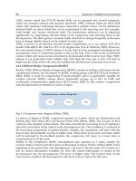
We analyze effects of atmospheric turbulence on the GEO satellite communications for
Ka-band at low elevation angles. Fig. 5 shows the propagation model between the earth
and the GEO satellite. The earth radius, the altitude of satellite and the elevation angle are
expressed by R, L and θ, respectively. A height of the top of atmospheric turbulence is shown
by h
t
. The z
L
is the distance from a transmitting antenna to a receiving antenna:
z
L
=
(R + L)
2
− (R cos θ)
2
− R sin θ, (25)
and z
ht
is the distance of propagation through atmospheric turbulence:
z
ht
=
(R + h
t
)
2
− (R cos θ)
2
− R sin θ. (26)
Note that z
L
z
ht
is satisfied for the GEO satellite communications. Therefore, for the uplink,
we can approximate z
− z
1
z in the integral with respect to z
1
in (21), and then express the
second moment of received waves at the GEO satellite:
M
11
(r
+
, r
−
, z
UL
)
A
(2π)
2
∞
−∞
dκ
+
exp
−
w
2
8
κ
2
+
+
jr
+
+
p
2
r
−
· κ
+
−
r
2
−
2w
2
0
−
k
2
4
z
UL
0
dz
1
z
1
0
dz
2
D
r
−
−
z
UL
k
κ
+
, z
1
−
z
2
2
, z
2
, (27)
Fig. 5. Earth – GEO satellite propagation model.
35
Theoretical Analysis of Effects of Atmospheric
Turbulence on Bit Error Rate for Satellite Communications in Ka-band
8 Will-be-set-by-IN-TECH
where z
UL
= z
L
, w = w
0
1 + p
2
, p = 2z
L
/(kw
2
0
) and the subscript of z
UL
denotes the uplink.
On the other hand, for the downlink, the statistical characteristics of a wave beam’s
incidence into atmospheric turbulence can be approximately treated as those of a plane
wave’s incidence. Thus the second moment of received waves at the ground station can be
approximately expressed by
M
11
(r
+
, r
−
, z
DL
)
2A
πw
2
exp
−
k
2
4
z
DL
0
dz
1
z
1
0
dz
2
D
r
−
, z
1
−
z
2
2
, z
2
, (28)
where z
DL
= z
ht
, w = w
0
1 + p
2
, p = 2( z
L
− z
h1
)/(kw
2
0
) and the subscript of z
DL
denotes
the downlink.
Here, the refractive index structure constant is assumed to be a function of altitude.
Referring to some researches for the dependence of the refractive index structure
constant in boundary layer (Tatarskii, 1971) and in free atmosphere (Martini et al., 2006;
Vasseur, 1999) on altitude, we assume the following vertical profile as a function of
altitude: h
=
(z + R sin θ)
2
+(R cos θ)
2
− R.
C
2
n
(h)=C
2
n0
1 +
h
h
s1
−2/3
, for 0 ≤ h < h
1
= C
2
n0
1
+
h
1
h
s1
−2/3
h
h
1
−4/3
, for h
1
≤ h < h
2
(29)
= C
2
n0
1 +
h
1
h
s1
−2/3
h
2
h
1
−4/3
exp
−
h − h
2
h
s2
, for h
2
≤ h ≤ h
t
Fig. 6. Vertical profile of refractive index structure constant as a function of altitude.
36
Advances in Satellite Communications
Theoretical Analysis of Effects of Atmospheric Turbulence on Bit Error Rate for Satellite Communications in Ka-band 9
ITEM VALUE
Carrier frequency (uplink / downlink): f 30.0/20.0 GHz
Velocity of light: c 3.0 × 10
8
m/s
Elevation angle: θ 5.0 deg
Aperture radius of an antenna in the GEO satellite 1.2 m
Aperture radius of an antenna in the ground station 1.2 to 7.5 m
Earth radius: R 6,378 km
Height of GEO satellite: L 35,786 km
Height of the top of atmospheric turbulence: h
t
20 km
Refractive index structure constant at the ground level: C
2
n0
1.0 × 10
−10
m
−2/3
Outer scale of turbulence: L
0
100 m
Inner scale of turbulence: l
0
1mm
Table 1. Parameters used in analysis.
where h
1
= 50 m, h
2
= 2, 000 m, h
t
= 20, 000 m, h
s1
= 2 m and h
s2
= 1, 750 m. Fig. 6 shows a
vertical profile of the refractive index structure constant. We assume C
2
n0
= 1.0 × 10
−10
m
−2/3
by referring to the profile of the standard deviation value obtained by Reference (Vasseur,
1999). We set L
0
= 100 m and l
0
= 1 mm.
Table 1 shows parameters used in analysis.
2.5 Modulus of complex degree of coherence
Using the second moment of received waves, we examine the loss of spatial coherence of
received waves on the aperture of a receiving antenna by the modulus of the complex degree
of coherence (DOC) (Andrews & Phillips, 2005) defined by
DOC
(ρ, z)=
M
11
(0, ρ, z)
[M
11
(ρ/2, 0, z)M
11
(−ρ/2, 0, z)]
1/2
, (30)
where ρ
= |ρ| is the separation distance between received wave fields at two points on the
aperture as shown in Fig. 7.
Fig. 7. Modulus of complex degree of coherence.
37
Theoretical Analysis of Effects of Atmospheric
Turbulence on Bit Error Rate for Satellite Communications in Ka-band
10 Will-be-set-by-IN-TECH
2.6 BER derived from average received power
We define BER derived from the average received power obtained by the second moment
of received waves. Here we assume a parabolic antenna as a receiving antenna. When a
point detector is placed at the focus of a parabolic concentrator, the instantaneous response
in the receiving antenna is proportional to the electric field strength averaged over the area
of the reflector. When the aperture size is large relative to the electromagnetic wavelength,
the electric field strength averaged over the area of the reflector in free space can be
described (Wheelon, 2003) by
u
in
(z)=
1
S
e
∞
−∞
dr u
in
(r, z)g(r), (31)
where S
e
is the effective area of a reflector. The field distribution g(r) is defined by a Gaussian
distribution of attenuation across the aperture with an effective radius a
e
:
g
(r)=exp
−
r
2
a
2
e
. (32)
Then the power received by the antenna in free space is given by
P
in
(z)=S
e
·
Re[u
in
(z) · u
∗
in
(z)]
Z
0
=
1
S
e
Z
0
· Re
∞
−∞
∞
−∞
dr
+
dr
−
M
in
11
(r
+
, r
−
, z) exp
−
2
a
2
e
r
2
+
−
1
2a
2
e
r
2
−
, (33)
where Re
[x] denotes the real part of x and Z
0
is the characteristic impedance. The energy per
bit E
b
can be obtained by the product of the received power P
in
(z) and the bit time T
b
:
E
b
= P
in
(z) · T
b
=
T
b
S
e
Z
0
· Re
∞
−∞
∞
−∞
dr
+
dr
−
M
in
11
(r
+
, r
−
, z) exp
−
2
a
2
e
r
2
+
−
1
2a
2
e
r
2
−
. (34)
We define the average energy per bit
E
b
affected by atmospheric turbulence as the product
of the average received power and T
b
. The average received power is given by the second
moment of received waves:
P(z) =
1
S
e
Z
0
· Re
∞
−∞
∞
−∞
dr
+
dr
−
M
11
(r
+
, r
−
, z) exp
−
2
a
2
e
r
2
+
−
1
2a
2
e
r
2
−
. (35)
Therefore,
E
b
= P(z)·T
b
=
T
b
S
e
Z
0
· Re
∞
−∞
∞
−∞
dr
+
dr
−
M
11
(r
+
, r
−
, z) exp
−
2
a
2
e
r
2
+
−
1
2a
2
e
r
2
−
. (36)
We consider QPSK modulation which is very popular among satellite communications. It is
known that BER in QPSK modulation is defined by
PE
=
1
2
erfc
E
b
N
0
, (37)
38
Advances in Satellite Communications
Theoretical Analysis of Effects of Atmospheric Turbulence on Bit Error Rate for Satellite Communications in Ka-band 11
where erfc(x) is the complementary error function. We define BER derived from the average
received power in order to evaluate the influence of atmospheric turbulence as follows:
PE
P
=
1
2
erfc
⎛
⎝
E
b
N
0
⎞
⎠
. (38)
And then, using E
b
in free space obtained by (34), the BER can be expressed by
PE
P
=
1
2
erfc
S
P
·
E
b
N
0
, (39)
where the normalized received power S
P
is given by
S
P
=
E
b
E
b
=
P(z)
P
in
(z)
=
Re
∞
−∞
∞
−∞
dr
+
dr
−
M
11
(r
+
, r
−
, z) exp
−
2
a
2
e
r
2
+
−
1
2a
2
e
r
2
−
Re
∞
−∞
∞
−∞
dr
+
dr
−
M
in
11
(r
+
, r
−
, z) exp
−
2
a
2
e
r
2
+
−
1
2a
2
e
r
2
−
. (40)
If the DOC is almost unity where the decrease in the spatial coherence of received waves is
negligible, the received power can be replaced with the integration of the intensity I
(r, z)=
|
u(r, z)|
2
over the receiving antenna. The received intensity in free space I
in
(z) and the average
received intensity affected by atmospheric turbulence
I(z) are respectively given by
I
in
(z)=
∞
−∞
dr M
in
11
(r, 0, z) exp
−
2r
2
a
2
e
(41)
I(z) =
∞
−∞
dr M
11
(r, 0, z) exp
−
2r
2
a
2
e
. (42)
Under the condition where the DOC is almost unity, we can reduce the number of the surface
integral in calculation of (40) and then obtain BER derived from the average received intensity
as follows:
PE
I
=
1
2
erfc
⎛
⎝
E
b
N
0
⎞
⎠
=
1
2
erfc
S
I
·
E
b
N
0
, (43)
where the normalized average received intensity S
I
is given by
S
I
=
E
b
E
b
=
I(z)
I
in
(z)
=
∞
−∞
dr M
11
(r, 0, z) exp
−
2r
2
a
2
e
∞
−∞
dr M
in
11
(r, 0, z) exp
−
2r
2
a
2
e
. (44)
39
Theoretical Analysis of Effects of Atmospheric
Turbulence on Bit Error Rate for Satellite Communications in Ka-band
12 Will-be-set-by-IN-TECH
3. Results
3.1 Modulus of complex degree of coherence
3.1.1 Uplink
Substituting (24) and (27) into (30), the DOC at the GEO satellite in the uplink can be described
by
DOC
(ρ, z
UL
)=
∞
0
dκ
+
2π
0
dθκ
+
exp
−
w
2
8
κ
2
+
+
p
2
κ
+
ρ cos θ −
ρ
2
2w
2
0
− H
ρ −
z
L
k
κ
+
,0,z
ht
·
2π
∞
0
dκ
+
κ
+
J
0
κ
+
ρ
2
exp
−
w
2
8
κ
2
+
− H
−
z
L
k
κ
+
,0,z
ht
−1
, (45)
where
H
ρ
,0,z
ht
=
12
5
(kπ)
2
L
5/3
0
z
ht
0
dz
1
0.033C
2
n
(z
1
)
·
1
+ Γ
1
6
1
κ
m
L
0
5/3
∞
∑
i=0
1
i!
1
κ
m
L
0
2i
1
F
1
−i −
5
6
;1;
−
κ
2
m
ρ
2
4
− exp
ρ
L
0
1
F
1
−
1
3
;
−
2
3
;
−
2ρ
L
0
, (46)
and
ρ
=
ρ
=
⎧
⎪
⎪
⎪
⎪
⎨
⎪
⎪
⎪
⎪
⎩
ρ
2
− 2ρ
z
L
k
κ
+
cos θ +
z
2
L
k
2
κ
2
+
in ρ
= ρ −
z
L
k
κ
+
z
L
k
κ
+
in ρ
= −
z
L
k
κ
+
.
(47)
Fig. 8 shows that the DOC in the uplink is almost unity within the size of an aperture diameter
of the receiving antenna of the GEO satellite (ρ
2a
e
). It means that the spatial coherence of
received waves keeps enough large within the receiving antenna.
3.1.2 Downlink
Substituting (24) and (28) into (30), the DOC at the ground station in the downlink is obtained
by
DOC
(ρ, z
DL
)=exp
− H
(
ρ, z
L
− z
ht
, z
L
)
, (48)
where
H
(
ρ, z
L
− z
ht
, z
L
)
=
12
5
(kπ)
2
L
5/3
0
z
L
z
L
−z
ht
dz
1
0.033C
2
n
(z
1
)
·
1
+ Γ
1
6
1
κ
m
L
0
5/3
∞
∑
i=0
1
i!
1
κ
m
L
0
2i
1
F
1
−i −
5
6
;1;
−
κ
2
m
r
2
4
− exp
r
L
0
1
F
1
−
1
3
;
−
2
3
;
−
2r
L
0
. (49)
40
Advances in Satellite Communications
Theoretical Analysis of Effects of Atmospheric Turbulence on Bit Error Rate for Satellite Communications in Ka-band 13
Fig. 8. The modulus of complex degree of coherence of received waves in the uplink for
various beam radius at the transmitting antenna as a function of the separation distance
between received wave fields at two points in the plane of the receiving antenna scaled by an
aperture diameter of the receiving antenna 2a
e
.
Fig. 9. Same as Fig. 8 except for the downlink where a beam radius at the transmitting
antenna w
0
= 1.2 m for various aperture radius of the receiving antenna a
e
.
41
Theoretical Analysis of Effects of Atmospheric
Turbulence on Bit Error Rate for Satellite Communications in Ka-band
14 Will-be-set-by-IN-TECH
As shown in Fig. 9, it is found that the decrease in the spatial coherence of received waves
can not be neglected within a receiving antenna of the ground station. It indicates that an
influence of the spatial coherence of received waves has to be considered in the analysis of
BER in the downlink.
3.2 BER derived from average received power
3.2.1 Uplink
The BER derived from the average received intensity defined by (43) and (44) can be used for
the uplink because the spatial coherence of received waves keeps enough large as shown in
Fig. 8. Using (24), (27), (43) and (44), the BER can be expressed by
PE
I
=
1
2
erfc
S
I
·
E
b
N
0
(50)
S
I
=
w
2
+ a
2
e
4
∞
0
dκ
+
κ
+
exp
−
w
2
+ a
2
e
8
κ
2
+
− H
−
z
L
k
κ
+
,0,z
ht
(51)
Fig. 10. BER derived from the average received intensity (PE
I
) in the uplink in w
0
= 7.5 m.
42
Advances in Satellite Communications
Theoretical Analysis of Effects of Atmospheric Turbulence on Bit Error Rate for Satellite Communications in Ka-band 15
H
−
z
L
k
κ
+
,0,z
ht
=
12
5
(kπ)
2
L
5/3
0
z
ht
0
dz
1
0.033C
2
n
(z
1
)
·
⎡
⎣
1
+ Γ
1
6
1
κ
2
m
L
2
0
5/6
∞
∑
i=0
1
i!
1
κ
2
m
L
2
0
i
1
F
1
−i −
5
6
;1;
−
κ
2
m
z
2
L
4k
2
κ
2
+
− exp
z
L
κ
+
kL
0
1
F
1
−
1
3
;
−
2
3
;
−
2z
L
kL
0
κ
+
. (52)
Fig. 10 shows the BER affected by atmospheric turbulence in the uplink when wave beams
are transmitted from the large aperture antenna where w
0
= 7.5 m. As reference, we plot a
dashed line as the BER in the absence of atmospheric turbulence given by (37). It is found
that BER increases compared with one in the absence of atmospheric turbulence. Because we
have already shown that the decrease in the spatial coherence of received waves is negligible,
we predict that the increase in BER is caused by the decrease in the average received intensity
due to spot dancing shown in Fig. 1.
3.2.2 Downlink
For the downlink, the decrease in the spatial coherence of received waves can not be ignored
as shown in Fig. 9. Therefore, we have to analyze the BER derived from the average received
power defined by (39) and (40) which include an influence of the spatial coherence of received
waves. Using (24), (28), (39) and (40), we obtain the BER as follows:
PE
P
=
1
2
erfc
S
P
·
E
b
N
0
(53)
S
P
=
1
a
2
e
∞
0
dr
−
r
−
exp
−
r
2
−
2a
2
e
− H
(
r
−
, z
L
− z
ht
, z
L
)
(54)
H
(
r
−
, z
L
− z
ht
, z
L
)
=
12
5
(kπ)
2
L
5/3
0
z
L
z
L
−z
ht
dz
1
0.033C
2
n
(z
1
)
·
1
+ Γ
1
6
1
κ
m
L
0
5/3
∞
∑
i=0
1
i!
1
κ
m
L
0
2i
1
F
1
−i −
5
6
;1;
−
κ
2
m
r
2
−
4
− exp
r
L
0
1
F
1
−
1
3
;
−
2
3
;
−
2r
−
L
0
. (55)
Fig. 11 shows the BER affected by atmospheric turbulence in the downlink when wave beams
are received by the large aperture antenna where a
e
= 7.5 m. It is found that the decrease
in the spatial coherence of received waves causes the decrease in the average received power
and result in the increase in BER. Note that an influences of spot dancing is negligible because
a statistical characteristics of received waves can be considered as a plane wave as mentioned
in the introduction of (28)
3.3 Effects of antenna radius of ground station on BER performance
In the system design of the ground station, we may increase an aperture radius of the ground
station’s antenna in order to satisfy the required Effective Isotropic Radiated Power (EIRP)
of the transmitter system or the G/T of the receiver system. In this section, we estimate an
effect of increasing an aperture radius of the ground station’s antenna on BER affected by
atmospheric turbulence.
43
Theoretical Analysis of Effects of Atmospheric
Turbulence on Bit Error Rate for Satellite Communications in Ka-band
16 Will-be-set-by-IN-TECH
Fig. 11. BER derived from the average received power (PE
P
) in the downlink in a
e
= 7.5 m
The EIRP of the transmitter system is defined as the product of a transmitting power and an
antenna gain of the transmitting antenna. The transmitting power P
t
is obtained by
P
t
=
1
Z
0
·
∞
−∞
dr
|
u
in
(r,0)
|
2
=
A
Z
0
, (56)
where u
in
(r,0) is given by (15). The antenna gain of the transmitting antenna G
t
is defined by
G
t
=
4πz
2
L
S
P
t
, (57)
where S denotes the received power density at
(0, z
L
):
S
=
|
u(0, z
L
)
|
2
Z
0
=
1
Z
0
·
2A
πw
2
. (58)
Thus, the antenna gain can be expressed by
G
t
=
4πz
2
L
S
P
t
=
8z
2
L
w
2
=
8z
2
L
w
2
0
(1 + p
2
)
2(kw
0
)
2
, (59)
where it is assumed that p
2
= 4z
2
L
/(k
2
w
4
0
) 1, which is satisfied in this model of analysis.
Using (56) and (59), the EIRP of the transmitter system can be described by
EIRP
= P
t
· G
t
=
2A(kw
0
)
2
Z
0
. (60)
44
Advances in Satellite Communications
Theoretical Analysis of Effects of Atmospheric Turbulence on Bit Error Rate for Satellite Communications in Ka-band 17
The G/T of the receiver system can be expressed by the ratio of an antenna gain of the
receiving antenna to the system noise temperature. The antenna gain of the receiving antenna
G
r
can be described by
G
r
=
4π
λ
2
S
e
= 4π ·
k
2π
2
·
πa
2
e
2
=
(
ka
e
)
2
2
, (61)
where S
e
= πa
2
e
/2 because the aperture efficiency of the receiving antenna, whose field
distribution is given by (32), is 0.5. The system noise temperature T
s
is obtained by
T
s
=
N
0
k
B
, (62)
where k
B
denotes Boltzmann’s Constant. Thus, the G/T of the receiver system can be
described by
G/T
=
G
r
T
s
=
k
B
N
0
·
(
ka
e
)
2
2
. (63)
On the other hand, using (19) and (34), E
b
/N
0
in free space is obtained by
E
b
N
0
=
P
in
(z
L
) · T
b
N
0
=
T
b
N
0
·
A
Z
0
a
2
e
w
2
+ a
2
e
T
b
k
B
T
s
·
A
Z
0
a
2
e
w
2
=
T
b
k
B
T
s
·
A
Z
0
· a
2
e
·
k
2
w
2
0
4z
2
L
, (64)
where it is assumed that a
e
/w 1. Using the EIRP and the G/T obtained by (60) and (63)
respectively, E
b
/N
0
in free space can be expressed by
E
b
N
0
=
T
b
k
B
·
A
Z
0
· 2(kw
0
)
2
·
1
(2kz
L
)
2
·
(
ka
e
)
2
2T
s
=
T
b
k
B
· P
in
· G
t
·
1
(2kz
L
)
2
·
G
r
T
s
=
T
b
k
B
· EIRP ·
1
(2kz
L
)
2
· G/T. (65)
Note that
(2kz
L
)
2
is the free space path loss.
3.3.1 Uplink
Using (65), we can describe BER derived from the average received intensity given by (50) in
the uplink:
PE
I
=
1
2
erfc
S
I
·
T
b
k
B
· EIRP ·
1
(2kz
L
)
2
· G/T
. (66)
Fig. 12 shows the BER as a function of kw
0
under the condition that G/T and EIRP keep
constant, where the transmitting power A/Z
0
changes in inverse proportion to the square
of kw
0
in (60). It is found that the BER affected by atmospheric turbulence increases as
kw
0
becomes large, whereas the BER in the absence of atmospheric turbulence plotted by
the dashed line does not change. Fig. 13 shows the BER for various beam radius at the
transmitting antenna w
0
as a function of E
b
/N
0
obtained by (65). It is shown that BER
increases as w
0
becomes larger as well as Fig. 12.
The reason for the increase in BER is as follows.
We have shown that spot dancing of wave beams due to atmospheric turbulence causes the
increase in BER for the uplink in Sec. 3.2.1. From each profile of the intensity in the absence
of atmospheric turbulence plotted by the dashed line in Figs. 14 to 17, it is found that the
45
Theoretical Analysis of Effects of Atmospheric
Turbulence on Bit Error Rate for Satellite Communications in Ka-band
18 Will-be-set-by-IN-TECH
Fig. 12. BER derived from the average received intensity in the uplink as a function of kw
0
when the EIRP of the transmitter system keeps constant.
Fig. 13. BER derived from the average received intensity in the uplink for various beam
radius at the transmitting antenna w
0
as a function of E
b
/N
0
.
46
Advances in Satellite Communications
Theoretical Analysis of Effects of Atmospheric Turbulence on Bit Error Rate for Satellite Communications in Ka-band 19
Fig. 14. Average intensity for the uplink in the beam radius at the transmitting antenna
w
0
= 1.2 m normalized by the intensity on a beam axis in free space as a function of the
distance from the center of the receiving antenna scaled by w
1
, which denotes the beam
radius at the plain of the receiving antenna for w
0
= 1.2 m.
Fig. 15. Same as Fig 14 except for w
0
= 2.5 m.
47
Theoretical Analysis of Effects of Atmospheric
Turbulence on Bit Error Rate for Satellite Communications in Ka-band
20 Will-be-set-by-IN-TECH
Fig. 16. Same as Fig 14 except for w
0
= 5.0 m.
Fig. 17. Same as Fig 14 except for w
0
= 7.5 m.
48
Advances in Satellite Communications