Applications of High Tc Superconductivity Part 4 pptx
Bạn đang xem bản rút gọn của tài liệu. Xem và tải ngay bản đầy đủ của tài liệu tại đây (5.11 MB, 20 trang )
Superconductivity Application in Power System
49
Fig. 4. General conceptual diagram of HTS cable system
2.2.1 HTS cable
Three kinds of HTS cable in outward appeareance are developed. Fig 5 shows single core
cable, co-axial core cable, tri-axial cable.
(a) Single core cable (b) tri-axial cable
(c) Co-axial cable
Fig. 5. HTS cable type classified by core
Usually, single core type is for transmission, tri-axial type is for subtransmission and co-
axial type is distribution.
The performance of HTS cable depends on the quality of HTS tape. HTS tape for power
cable has to be produced long enough to fulfill the required length of cable core to be
Applications of High-Tc Superconductivity
50
installed, also have sufficient critical current density and uniform current and good
mechnical characteristics.
Recently, the improvement of critical current and length in Bismuth series high temperature
superconducting wire make possible to realize HTS power cable application in real field.
BSCCO-2223, the recently developed HTS conductor which has almost 110[K] critical
temperature, is mainly applied to make HTS cable.
Fig. 6 shows CD type HTS cable cross section. It is composed with Former(copper),
conductor(HTS), Electrical Insulation(PPLP), electrical shielding(HTS), stainless sheath for
thermal insulation and cladding material.
Fig. 6. Cross section of HTS cable(CD type, for distribution system)
Table 2 shows one of HTS cable specification for 22.9kV distribution line. It is designed for
replace present distribution cable system without changing underground right of way.
Item Specification
Former Stranded copper
Conductor Bi-2223, 2 layer
Shield layer Bi-2223, 1 layer
Electrical insulation PPLP, 4.5 mm
Cable core diameter 35 mm
Superconductor/shield Bi-2223 tape
Thermal insulation Double corrugated pipe, MLI, Vacuum
Oversheath PE
Cable outer diameter 130 mm
Table 1. Example of HTS cable specifications (CD type, for distribution system)
2.2.2 Cooling facility
Cooling facility is another important component of HTS cable system to maintain
superconductivity with sufficient low temperature at various operating conditions. In fig.7,
LN2 flows LN2 line, superconducting cable, refrigerator and pump. Cryostat prevents heat
transfer from cable inner and outer.
Superconductivity Application in Power System
51
Fig. 7. HTS cable system at Albany project
2.2.3 Termination
Termination locates both ends of HTS cable. It connects HTS cable and normal temperature
power line. Because of large difference of temperature between HTS cable and outer
weather, termination has to sustain temperature difference and pump out heat from joint
resistance.
2.2.4 Monitoring system
Monitoring system checks electrical and thermal status of HTS cable system. Electrical
variables are currents and voltages. Thermal variables are temperatures of every
components, such as cable inlet, outlet, refrigerator inlet and outlet etc.
2.3 Characteristics of HTS cable
2.3.1 Electrical characteristics
Brief comparison of electric characteristics among power delivery systems are suggested in
table 2.
WD type can transfer about 2 times power than conventional cable at same power loss,
however, CD type can transfer about 4.5 times power. Below table shows brief comparison
between WD and CD type.
conventional HTS(WD) HTS(CD)
Pipe outer diameter(mm) 200 200 200
Voltage(KV) 115 115 115
Power rating(MVA) 220 500 1000
power loss(W/MVA) 300 300 200
Table 2. Comparison of ratings between WD and CD HTS power cable
Applications of High-Tc Superconductivity
52
The capacity of WD HTS cable is about 2.5[kA] per phase at 132/150~400[kV] transmission
voltage and 500~2000[MVA] per system[2]. CD type has better current capacity than WD
type, 8[kA]/phase. Also, DC HTS cable can transfer 15[kA] and more at same design.
Power delivery
system
Cable dimension Electrical constants(Z
1
/Z
0
)
Inside
Radius
[mm]
Outside
Radius
[mm]
Shield
Radius
[mm]
Resistance
[Ω/km]
Inductance
[mH/km]
Capacitance
[nF/km]
Conventional XLPE 2 25 40 0.03/0.15 0.36/1.40 257/175
HTS WD type 12.7 14 29
0.0001/
0.12
0.39/1.47 217/175
HTS CD type(VLI) 12.7 14 29
0.0001/
0.03
0.06/0.10 200/140
Table 3. Comparision of electrical constants between WD and CD HTS power Cable
Table 3 introduces the electrical constants of HTS cable. We can find that CD type cable has
only 1/6 positive sequence inductance over WD and XLPE cable which acts as impedance in
AC system. This tells us CD type HTS cable shows excellent power transfer capability at
steady state.
However, it has quench property if the conductor temperature rise over critical temperature,
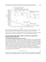
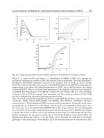
the resistivity increase dramatically. See Fig.8.
Fig. 8. Temperature and Resistivity of HTS conductor
2.3.2 Thermal characteristics
To sustain superconductivity of HTS cable in normal operation, it is very important to keep
the temperature of cable system within permissible range. Depend on above figure, if
temperature rise over about 97[K], quench happens.
Superconductivity Application in Power System
53
Fig. 9. Inlet and outlet temperature of HTS cable
Above figure shows the temperatures of inlet and outlet of HTS cable during load cycling
operation. At both terminal, temperatures are below 73[K] and there are about 24 degrees
temperature margin.
2.3.3 Operational characteristics of HTS cable system in sample system
In this section, a sample of distribution level HTS cable operation status shall be introduced
to understand each electrical components response to steady and transient state. HTS cable
may be operated at unbalanced 3 phase currents, harmonics, various fault condition. Well
designed HTS system has to survive expected abnormal state.
2.3.3.1 Sample system
22.9kV, 50MVA distribution CD type HTS cable applied sample system is introduced in
Fig.8 and Table 4.
Fig. 8. Model distribution system
Applications of High-Tc Superconductivity
54
Items Specification
Rated Voltage 22.9 kV
Rated Current 1,250 A
Capacity 50 MVA
Length 100 m
Cable Type 3 cores in one cryostat
Dielectric Type Cold dielectric
Cable Size Applicable for 175 mm duct
Response to Fault
Current
There shall be no damage for the cable and cable system when
the fault of 25kA is applied to the cable for 5 cycles.
Table 4. Ratings of modeled HTS cable
Fig. 9. CD type HTS cable modeling
To verify electrical characteristic more detail, each conductors and formers are modeled
with EMTDC and compared with test results.
2.3.3.2 Normal operation characteristics –3 phase balanced case
When the operating current of HTS cable increased up to 2/3 of rated current, the conductor
and shield current are measured[Fig 10]
(a) Test (b) Simulation
Fig. 10. Test and simulation results (Balanced case 800A
rms
: conductor and shield current)
Superconductivity Application in Power System
55
In a) and b), currents in conductor and shield are almost same and opposite phase. Errors of
measured and simulated value are 1.7%(HTS conductor) and 0.7%(Shield), respectly. This
errors are regarded as heat characteristics and AC loss effects of HTS cable.
Abnormal operation characteristics – 3 phase unbalanced case
Fig. represents the test and simulation results of 30% unbalanced case. Errors between test
and simulation reaches 6.5% maximum.
(a) Test (b) Simulation
Fig. 11. Test and simulation results (Unbalanced case 600/600/800Arms: conductor and
shield current)
2.3.3.3 Abnormal operation characteristics – harmonics
Harmonics can increase AC loss of HTS cable due to hysteresis loss. Hysteresis loss model is
as below equation.
=
[W/m
3
] (1)
f : frequency [Hz]
B : flux density[Wb/m2]
n : exponential index on material [2.1]
V : volumn of material
k : total constant
In case of high THD, especially higher order harmonics are included dominantly, the
hysteresis loss will be increased because it is proportional to frequency. Regarding
harmonics, HTS cable system has to increase cooling capacity and/or decrease operating
capacity of HTS cable.
2.3.3.4 Abnormal operation characteristics-fault currents and thermal characteristics
In abnormal operation status such as short curcuit current passing condition,
superconducting cable has to pass large current securely. Usually, fault current rises 10
times more than normal current, this excessive current may over critical current (Ic) of
superconductor. In this case, current quench may happen and very rapid temperature rise
may take place and the HTS cable may be damaged . Therefore, various methods such as
fast circuit breaker and/or parallel conductor(copper former) are applied to protect quench
of HTS conductor.
Applications of High-Tc Superconductivity
56
In CD type HTS cable, most of fault currents are transferred from HTS conductor to former
conductor because of superconductor resistance rise. When temperature is supposed as
constant, HTS conductor resistance is calculated by next equation.
(1)
Fig. 12. V-I curve of 66kV HTS cable
During fault current, the internal heat dynamics can be approximately fomulated by heat
insulated equation because electric dynamics ends within very short time(0.1 seconds)
compare to heat dynamics.
Therefore, quench dynamics are represented next heat balnace differential equation.
(2)
C(T) : heat capacity
The left side represent temperature rising rate of HTS cable, the first term of right side
represent heat transfer to superconductor, and k(T) is heat transfer rate, Q(T) is internal heat
generation due to current, W(T) is cooling heat.
Therefore,
(3)
I(t) is current, ρ is resistivity of tape, A is cross secion area.
If we suppose fault current flows within very short time, heat transfer and cooling effect can
be disregarded. Therefore, equation (2) simplified as (4).
(4)
Superconductivity Application in Power System
57
In quench state, voltage of quench area will be increase and cable impedance(R+jX) is
increased too.
Every nonconductors in cable acts heat resistances of heat tranfer. The heat resistance of
each insulation can be calculated as follows.
(5)
T : Heat resistance of each insulation layer in unit length [K·m/W].
ρ
th :
heat resistance of material
r
1
, r
2
: inner and outer radius of insulator
Most of problem related cable rating is determined by passed time and modeled by heat
balance equation. However, solving it is very difficult with numerical analysis. Therefore, in
most calculation case, we define heat capacity of cable as equation (6) and use simple
approach.
(6)
V = cable volumn[m
3
]
c = heat capacity of material [J/m
3
℃]
Next Figure represents and example of heat equivalent circuit between conductor and
sheath of cable. Qc represents heat capacity of conductor and sheath. Heat capacity of
dielectrics are calculated.
Fig. 13. Equivalent heat transfer circuit of HTS cable
T
1
: Total heat resistance of dielectric material
Qi : Total heat capacity of dielectric material
Qc : heat capacity of conductor
heat capacity coefficient ρ can be calculated equation (7)
(7)
D
i
: Cable inner diameter
d
c
: conductor diameter
Applications of High-Tc Superconductivity
58
2.3.3.5 Fault example - single line fault case
Fig. 14 shows the simulation results of single line to ground fault case on above distribution
system
(a)
(b)
Fig. 14. Current and temperature of HTS cable in fault condition(SLG)
(a) fault current at Single line fault (b) temperature of conductor and shield
Superconductivity Application in Power System
59
With the fault current of A phase, HTS conductor of phase A temperature rises from 67[K]
to 97[K] during fault time. If quench temperature is 105[K] normally, there is little margin to
this HTS cable system.
3. Superconducting Fault Current Limiter(SFCL)
3.1 Fault Current Limiter and SFCL
In electrical network, there are various faults, such as lightning, short circuits, grounding etc.,
which occurs large fault current. If these large currents are not properly controlled for power
system security, there happens unexpected condition like fire, equipment and facility damage,
and even blackout. Therefore, Circuit Breakers are installed and have the duty to cut off fault
current, however, it takes minimum breaking time to cut, and sometimes fail to break.
Fault Current Limiter(FCL) is applied to limit very high current in high speed when faults
occur. Different with normal reactor, normal impedance is very low and have designed
impedance under faulted situation. Fault limiting speed is high enough that it can limit fault
current within 1/4 cycle. Also, this function has to be recovered fast and automatically, too.
Various FCLs are developed and some of them are applied in power system. Most typical
FCL is to change over circuit from low impedance circuit to high impedance circuit. Circuit
breakers and/or power electronics devices are used to control FCL circuits. Fuse or snubber
circuits are used to protect high recovery voltage. These FCLs are attractive as it implements
normal conductor, however, there are weak points such as slow current limiting speed and
big size in distribution and transmission level as well.
Superconducting fault current limiter (SFCL) has been known to provide the most
promising solution of limiting the fault current in the power grid. It makes use of the
characteristic of superconductor whose resistance is zero within critical temperature (Tc)
and critical current (Ic). If fault current exceeds Ic, superconductor lose superconductivity
and the resistance increase dramatically (called quench) and limit circuit current.
3.2 Classification of SFCL
Various types of SFCLs have been built and showed desired current limitation up to
medium voltages. Some of them were actually field-tested in the electrical power grid.
However, the SFCLs seem to be not near to commercial operation in the grid. This means
that the SFCL is not ready to satisfy the utilities in various conditions. The conditions are
dependent upon the application conditions, general purpose applications and special
purpose ones.
We can classify these SFCLs as three types, which are resistance type(R-type), Inductance
type (L-type) and saturable core type. R-type makes use of quench resistance of
superconductor directly. L-type makes use of superconductor as trigger element for circuit
inductance which limits fault current. Saturable core type makes use of superconductor
magnet to saturate reactor iron core. In normal operation, this reactor has a little reactance in
saturation state. However in fault state, fault current releases saturation state and increases
impedance, therefore limits fault current.
3.2.1 R-type and L-type
The conceptual circuit of R-type and L-type SFCL is shown Fig. 15. In SFCL(Limiter), R
p is
fault limiting resistance when R-type. In case of L-type, R
p will change as Lp (fault limiting
inductance). If i
ac reaches critical current, Rsc should be quenched and its superconducting
Applications of High-Tc Superconductivity
60
characteristics will be lost (resistance will be increased dramatically) , so fault current will be
limited by R
p
.
Fig. 15. R-type and L-type SFCL conceptual circuit
The mathematical model of SFCL is expressed as equation (8).
(8)
T
s
is time constant of impedance, t
0
is delay time of SFCL, Zs is impedance of SFCL.
(9)
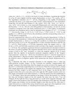
By the equation (8), impedance dynamics of SFCL is as Fig. 16.
Fig. 16. Characteristics of SFCL impedance
R-type SFCL can limit peak current if proportional to Rs. L-type has slow damping
characteristic because of transient DC component. The superconductor resistance value of
SFCL (Rsc) is dependent to its type, it rise about 25 [pu] exponentally within 1[ms].
Superconductivity Application in Power System
61
3.2.2 Saturable core type
The conceptual circuit diagram of saturable core type SFCL is shown Fig. 17. In normal
state, two core fluxs are saturable with currents I
o
. When fault current i
ac
flows, saturable
fluxs are decreased and inductance of L1 and L2 increase along with B-H curve.
Fig. 17. Saturable core type SFCL conceptual circuit
Fig. 18. Saturable core type characteristics
3.2.3 Hybrid type
Currently two types of SFCLs are widely developed at medium and high voltage scale, the
resistive type and the saturable iron-core type SFCLs. Since a resistive SFCL component is
limited in current and voltage ratings, inevitable is a large number of components to be
assembled, so a large cryostat to cool them. Likewise, the saturable iron-core type carries
large size iron cores.
To match these requirements, hybrid SFCL is developed for medium voltages class. The
hybrid structure is composed of superconducting parts and conventional switches. This
resulted in drastic reduction of superconductor volume, followed by smaller cryostat. The
Applications of High-Tc Superconductivity
62
design also provides standing alone current limitation, reclosing capability, and other
functions.
Fig. 19. Design innovation of resistive SFCLs. (a) conventional resistive type, (b) hybrid type
with a conventional breaker, (c) hybrid type with a fast switch
3.3 Developed/Applied SFCLs
The first installed one is developed by ABB. After that, various SFCLs are developed for
distribution and transmission application to protect bus and/or feeder from high fault
currents . Fig. 20 shows recently developed and installed SFCLs for distribution level.
(a) (b) (c)
Fig. 20. Distribution class SFCLs, (a) Boxberg, Germany (b) Shandin, USA, (c) Kochang,
Korea
Superconductivity Application in Power System
63
place developer Voltage (kV) Type status
ABB P/P, Swiss ABB 10.5 R-type
Operated
1997(6month)
Puji S/S, China Innopower 10.5
Saturable
Core
In operation (2008~)
SCE Shandin S/S
USA
Zenergy Power 15
Saturable
Core
In operation (2009~)
Tokyo Gas, Japan Toshiba 6.6 In operation (2007~)
Lancashire, U.K Nexans SC 12 R-type In operation (2010~)
Boxberg P/P,
Germany
Nexans SC 12 R-Type In operation (2009~)
San Dionigi S/S
Italy
CESI
RICERCA
9 R-Type In operation (2011~)
Kochang, Korea KEPRI/LS 22.9 Hybrid In operation (2009~)
SCE, USA AMSC/Siemens 115 R-Type In operation (2011~)
AEP, USA ZenergyPower 138
Saturable
Core
In operation (2011~)
Table 5. SFCL Developments for Transmission level
3.4 Applications of SFCL
The utilities used to require that the SFCL must be robust, reliable, of low cost, and (almost)
maintenance-free for long time use. These would be universal conditions that any SFCL is
expected to satisfy. In addition, there may be local conditions associated with the special
purpose application of an SFCL by local demands. The local conditions may be specific size,
cost, current limitation performance, reclosing capability, and so on.
Fig. 21. SFCL sample system
Applications of High-Tc Superconductivity
64
SFCL has many good points, such as small size, faster fault current limiting, little parts, no
power increase in fault circuit. Therefore, various applications are expected as belows, for
example.
Increase power transfer flexibility applied to bus-tie between distribution transformers
Reduce voltage sag applied to sensitive load.
Reduce ground fault current applied to neutral impedance for transformer
Below is case study result how SFCL is work in 22.9kV distribution system.
variables L
limit
R
limit
rA
quench
(normal)
rA
quench
(fault)
Value 0.005[H] 1.0[Ω]0[Ω]
Table 6. Constants of sample SFCL
In this simulation, maximum quench resistance is 5 [Ω]. Fig 22 shows how SFCL limits fault
current compare to non-SFCL circuit. The fault current could be reduced dramatically
within 1/4 cycle by SFCL.
Fig. 22. Simulation result of SFCL dynamics
4. Dynamic Synchronous Condenser (DSC : SuperVar)
Synchronous Condensers (SC) are a good facility to support dynamic reactive power both
capacitive and inductive area to improve system voltage characteristics. They are rotating
machine rotating in synchronous speed. When we operate a synchronous generator
connected power grid without driving motor, it is operated as synchronous condenser.
Its reactive power can be controlled with field current excitation. When overexcited, it
generates capacitive reactive power. If under-excited, it generates inductive reactive power.
Today, this machine is not preferred because of high power loss and maintenance problem.
Static reactive compensators such as STATCOM (Static Compensator) and/or SVC (Static
Var Compensator) are preferred alternatives with rapid response and easy maintenance.
However, synchronous condenser has excellent characteristic to support dynamic rating
compare to above static compensators.
Dynamic Synchronous Condenser (DSC) has upgraded existing SC technology by using a
conventional armature mated with a field winding made from High Temperature
Superconductivity Application in Power System
65
Superconducting (HTS) wires. With the upgrading of field magnetic flux density as HTS
conductor, it can provide up to 8 [pu] current for short periods to support transient VAR
requirements. Key benefits of DSC are as follows:
Fast response to transient voltage variation at both reactive power
Low losses
Simple installation (small footprint)
Low maintenance
No harmonic generation
4.2 Configuration
The major components of a DSC are shown in Figure 23. The field winding employs HTS
conductor which is cooled with a cryocooler to about 35-40K. The cryocooler modules are
located in a stationary frame and a fluid such as gaseous helium or liquid neon is employed
to cool components on the rotor. The stator winding employs
conventional copper
windings.
(a)
(b)
Fig. 23. Conceptual diagram of a DSC
(a) superconducting field winding in cryocooler , (b) DSC model picture
Applications of High-Tc Superconductivity
66
4.3 Electric characteristics and performance
The DSC has low synchronous reactance which increases power system stability and
reactive power/voltage compensation compare to a conventional SC. The characteristics
DSC are summarized below:
With low synchronous reactance, DSC provides less voltage drop ratio between no-load
and full-load operations
The sub transient reactance (x
d
”) of the machine is also low (0.11 pu) which lets the
machine provide up to 8 pu first peak current for a terminal short circuit.
The major parameters of the machine are shown in table 7.
Parameters value
Synchronous reactance (x
d
) 0.5 pu
Transient reactance (x
d’
) 0.22 pu
Sub-transient reactance (x
d”
) 0.11 pu
Armature short-current time constant ( )
0.045 sec
D-axis transient short circuit time constant (
)
7.31 hr
D-axis transient short circuit time constant (
“)
0.01 sec
Armature resistance (r
a
) 0.007 pu
Table 7. DSC electric parameters
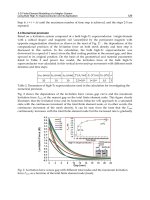
Figure 24 compares the efficiency of the DSC with a conventional synchronous condenser.
The HTS field winding eliminates 50% of conventional machine field losses. Especially, It
has good efficiency in light load condition.
Fig. 24. DSC versus conventional machine efficiency
The DSC has no dynamic stability limit within its MVA rating. The machine can run stably
without requiring any feedback control for dynamic voltage stabilization. This machine also
has a superior dynamic stability during small oscillations and requires no field forcing for
damping such oscillations. Figure 25 shows its damping of oscillations following a sudden
change of load.
Superconductivity Application in Power System
67
Fig. 25. DSC damping of low frequency oscillation following sudden load change
5. Application to power system
5.1 HTS cable
Before HTS cable application to power system, system planners have to understand the
characteristics of power system and HTS cable. HTS cable system shall be applied special
place in network which requires higher density power transmission.
There are several feasibility studies for HTS cable application. J. Jipping et al examined
application validity of HTS cable for future load growth in a viewpoint for heat capacity and
fault current. D. Politano et al examined technical economical efficiency for substitution high
voltage transmission line for HTS cable. K. C. Seong et al examined transmission capability
problem of power systems in a viewpoint for power flow and examined validity for HTS
cable application. G.J.Lee et.el[ ] presented HTS cable application method to increase
voltage stability limit. Recently, Ultera finished feasibility study of Amsterdam HTS project
which will connect 6km, 50kV 250MVA HTS cable in 2013~2014 to increase inter-substation
power transfer. Also, AMSC is planning to use DC HTS cable to interconnect North America
network (Tres-Amigas Project).
For every application, total power system planning techniques are needed for the future’s
HTS cable implementation.
In this section, an example of HTS application study method shall be introduced to increase
voltage stability limit. Fig 26 represents study procedure .
5.1.1 Case study
Sample system and verify initial transfer capacity
IEEE 39 bus system is considered for the sample system (Fig. 27). N-1 contingency is applied
to estimate initial steady state transfer capacity. From the initial load condition (6098MW),
maximum incremental transfer capacity applied N-1 contingency case is 3900MW.
Therefore, system transfer capacity regarding security limit is 9,998MW.
Applications of High-Tc Superconductivity
68
Fig. 26. Analysis procedure of HTS cable application