Novel Applications of the UWB Technologies Part 4 ppt
Bạn đang xem bản rút gọn của tài liệu. Xem và tải ngay bản đầy đủ của tài liệu tại đây (827.8 KB, 30 trang )
A 0.13um CMOS 6-9GHz 9-Bands
Double-Carrier OFDM Transceiver for Ultra Wideband Applications
77
C. Mishra, A. Valdes-Garcia & F. Bahmani, et al., “Frequency planning and synthesizer
architectures for multiband OFDM UWB radios”, IEEE transaciton on microwave
theory and techniques, vol. 53, pp. 3744-3756, Dec. 2005
D. Leenaerts, R. Beek, G. Weide, J. Bergervoet, K. Harish & H. Waite, et al., “A SiGe BiCMOS
1ns Fast Hopping Frequency Synthesizer for UWB Radio”, ISSCC 2005, pp. 202-203,
February 2005.
H. M. Chien, T. H. Lin & B. Ibrahim, “A 4GHz fractional-N synthesizer for IEEE 802.11a”,
IEEE VLSI, pp. 46-49, Jun. 2004
Huang Zue-Der, Kuo Fong-Wei, Wang Wen-Chieh & Wu Chung-Yu, “A 1.5-V 3~10-GHz
0.18-µm CMOS frequency synthesizer for MB-OFDM UWB applications”, 2008
MTT-S International Microwave Symposium Digest, pp. 229-232, June 2008
Kuo C., Chang J. & Liu S., “A Spur-Reduction Technique for a 5-GHz Frequency
Synthesizer”, IEEE Trans. Circuits and Systems—I: Regular Papers, Vol. 53, NO. 3,
March 2006, pp.526-533.
Liang C.F., Liu S.I., Chen Y.H., Yang T.Y. & Ma G.K., “14-band frequency synthesizer for
MB-OFDM UWB application”, IEEE Int. Solid-State Circuits Conf. Dig.Tech. Papers
(ISSCC), pp. 126-127, Feb. 2006
Nauta B. A CMOS Transconductance-C Filter Technique for Very High Frequencies. IEEE
journal of Solid-State Circuits,1992, 27: 142-152
Nikookar, R. Prasad. Introduction to Ultra Wideband for Wireless Communications,
Signals and Communication Technology, B.V.: Springer Science & Business
Media, 2009.
P.Andreani.”A Low-Phase Noise,Low Phase Error 1.8 GHz Quadrature CMOS VCO”,
ISSCC 2002, pp.290–291,February 2002.
Shin D. H., Park J. & Yue C. P. A Low-Power, 3-5-GHz CMOS UWB LNA Using
Transformer Matching Technique.IEEE Asian Solid state circuits conference, 2007,
95-98
Sjöland H, Karimi-Sanjaani A & Abidi A A. A merged CMOS LNA and mixer for
a WCDMA receiver [J]. IEEE Journalof Solid-State Circuits, 2003, 38(6): 1045-
1050.
Tanaka A, et al. 1.1 V 3.1-to-9.5 GHz MB-OFDM UWB transceiver in 90 nm CMOS. IEEE
International Solid-State Circuits Conference, 2006, 120-121
T.Deliyannis, Sun Yichuang & J. Kel Fidleret, Continuous-Time Active Filter Design, Boca
Raton: CRC Press LLC, 1999.
Wang C.S., Li W.C., Wang C.K., Shih H.Y. & Yang T.Y., “A 3-10GHz full-band single VCO
agile switching frequency generator for MB-OFDM UWB”, IEEE Asian Solid-Sate
Circuits Conference, pp.75-78, Nov. 2007.
Willy Sansen, Analog Design Essential, Springer Press, 2006.
Werther O, et al. A fully integrated 14-band 3.1-to-10.6 GHz 0.13 _m SiGe BiCMOS
UWB RF transceiver. IEEE International Solid-State Circuits Conference, 2008,
122-123
Zheng H., Lou S. H. & Lu D. T., et al. A 3.1 GHz-8.0 GHz Single-Chip Transceiver for MB-
OFDM UWB in 0.18_m CMOS Process. IEEE journal of Solid-State Circuits, 2009,
44: 414-426
Novel Applications of the UWB Technologies
78
Zheng Renliang, Ren Junyan & Li Wei, et al., A 3.1-4.8 GHz transmitter with a high
frequency divider in 0.18m CMOS for OFDM-UWB, Journal of Semiconductors,
2009, 30(12):25003-1–8.
Zisan Zhang, Koen Mertens & Marc Tiebout. A 6-9 GHz WiMedia UWB RF Transmitter in
90nm CMOS, IEEE Radio Frequency Integrated Circuits Symposium, 2008:39.
0
Implementation-Aware System-Level
Simulations for IR-UWB Receivers: Approach
and Design Methodology
Marco Crepaldi
1
, Ilze Aulika
1
and Danilo Demarchi
2
1
Center for Space Human Robotics @Polito,
Istituto Italiano di Tecnologia, Corso Trento, Torino
2
Dipartimento di Elettronica (DELEN),
Politecnico di Torino, Corso Castelfidardo, Torino
Italy
1. Introduction
Impulse-Radio Ultra-Wide Band technology (IR-UWB) allocates very large bandwidth with
short duration pulses. Interest for research started in 2002 when Federal Communication
Commission (FCC) normed the power spectral densities allowed for unintentional and
unlicensed UWB radiators in the pre-existing full communication band 0-10 GHz FCC (2002).
An ultra-wide band pulse has some unique features compared to conventional wireless
signals. If on the one hand, narrowband signals envelope is close to a time unlimited
continuous function, on the other hand, in a possible conception pulses can be perfect duty
cycled tones having limited time support. Pulses with very short duration occupy very large
bandwidth and this is in contrast to the narrowband approach, that subdivides the available
spectrum into small slices for efficiently allocating radiated power. IR-UWB is then very
interesting because it poses these kinds of challenges, i.e. the use of pulses and the coexistence
with the existing RF systems.
The use of short duration pulses implies a physical limitation which normally narrowband RF
systems are excluded from. These are multipaths, that is reflections from the objects localized
in the operating environment. This has conditioned the use of IR-UWB for very high data rates
applications because notwithstanding the very large theoretical channel capacity, a very high
data rate communication is now almost infeasible with low complexity electronics tackling
multipath diversity. IR-UWB has then been proposed for short/medium range Ultra-Low
Power (ULP) communication Wireless Sensor Networks (WSN) Bielefeld et al. (2009); IEE
(2007); Lecointre et al. (2010); Stoica et al. (2005); Verhelst & Dehaene (2008); Wang et al.
(2011). At the transmitters very low average consumed power is possible with aggressive duty
cycling, as well as in receivers even if with lower efficiency. Transmitters radiate dBm-order
power signals in just 1-3 ns and receivers typically demodulate and synchronize data by
detecting the presence of the UWB pulses with time domain computations.
One important key-word for understanding how IR-UWB will possibly impact on new ULP
applications is “system-level”. The validation of a receiver or a transmitter architecture
being aware of the impact of blocks physical implementation prior to full low-level
4
2
design can possibly lead to significant performance increase and help lower complexity.
Based on these considerations, this book chapter shows a methodology used for IR-UWB
receivers simulation, design and conceptualization. A multi-level approach is presented and
contextualized with an implementation example, that is an energy detection receiver. This
design methodology has been already presented in Crepaldi et al. (2007) and extensively used
in Casu et al. (2008). In this book chapter we expand it and provide more comments and
considerations based on successive works dealing with IR-UWB system-level design.
Section 2 considers an Energy Detection receiver as a case study and section 3 introduces
the design methodology after emphasizing its requirements. Later, section 4 applies the
methodology to a specific block of the receiver and section 5 shows the obtained simulation
results. Section 6 concludes the chapter.
2. A case study: the Energy Detection receiver
IR-UWB Energy Detection receivers represented mostly the number one choice for WSN and
have been widely integrated and researched starting the second half of 2000-2010 decade
Crepaldi et al. (2010); Daly et al. (2009); Lee & Chandrakasan (2007). Energy detection
receivers are robust and of easy implementation notwithstanding being non-coherent,
therefore sub-optimal. In the beginning, research was focused on conceptualized architectures
that studied the communication performance of IR-UWB and attempted to solve some
system-level issues. An example for non-coherent M-PPM receivers is given in Carbonelli
& Mengali (2006). The proposed architectures did not deeply account for circuit-level
implementation details. Starting from this first conceptualization mechanism, first energy
detection receivers have been proposed Stoica et al. (2005), Lee & Chandrakasan (2007).
By then all the required system-level performance figures were validated on silicon for
the first time. This, and the successive receivers proposed by then, aimed towards lower
energy consumption or to increase performance of some of these reference points. In this
book chapter we refer to a somewhat old energy detection receiver scheme, in which an
Analog-to-Digital Converter (ADC) is used for data demodulation as well the use of other
blocks that differ compared to recent implementations. Here, we explicitly utilize this scheme
because it represents a case study, and still, valid ideas can emerge from the analysis of this
system from cross-sectional views.
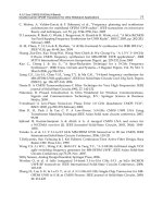
A standard energy detection receiver block scheme is depicted in fig. 1. The complete
transceiver is assumed to be fully implemented as a silicon System-on-Chip (SoC) and
at this stage the transmitter is assumed to be only behaviorally modeled. The antenna
switch commutates the wideband antenna to receiver and transmitter ends, while an external
Band-Pass Filter (BPF) ensures that on-chip generated UWB pulses satisfy the FCC mask and,
at the same time, filters out-of-band interference from the received ones. The energy detector,
depicted in the front-end part is composed of a linear amplification block, the Low-Noise
Amplifier (LNA), Variable Gain Amplifiers (VGA) a squaring unit and an Integrate&Dump
(I&D). The receiver computes the raw pulse energy. By assuming that integration generically
starts at t
a
and ends at t
b
, Ar(t) is signal at the output of the VGA, where A is the gain of the
previous blocks, the energy E at the output of the I&D is,
E
=
t
b
t
a
A
2
r(t )
2
dt (1)
To run both synchronization and demodulation the receiver circuitry operates on t
a
and
t
b
to detect for example the maximum energy peak and, for 2-PPM receivers, activate
80
Novel Applications of the UWB Technologies
Implementation-Aware System-Level Simulations for IR-UWB Receivers: Approach and Design Methodology 3
Transmitter
LNA
DC/PMU
VGA
RF
Analog
Data
Demod &
Processing
AGC
Receiver front end
Simulated Blocks
Antenna Switch
Digital data
Analog data
Antenna
UWBTRX
( )
2
Counter
I & D ADC
BPF
Synch
Mixed
Digital
NE/PS
Fig. 1. Energy Detection transceiver block scheme Crepaldi et al. (2007).
integration once pulses timing is acquired at the correct ’1’ or ’0’ bins. For gain control the
receiver operates on parameter A with an digital-to-analog feedback from the demodulation
chain. After energy is calculated it is quantized with an ADC and then processed by the
back-end that can implement a threshold based demodulation algorithm for OOK, or a relative
comparison as in the case of 2-PPM. Here the receiver operates with 2-PPM modulation.
The Data processing block controls also the synchronization unit, that operates similarly
to a Delay-Locked-Loop (DLL) for searching the maximum energy peak within a known
preamble. The Automatic Gain Control unit (AGC) automatically sets the front-end gain
based on the digitized energy. The NE/PS block, namely Noise Estimation&Preamble Sensing
block, helps detecting the presence of a preamble once the receiver is activated and collects
energy samples from channel when no pulse is transmitted. This helps assessing the clearance
of channel as soon as receiver is activated, therefore allowing system shutdown in case no
packet is received. Data saved by this digital block is used for adjusting the gain of the
receiver front-end for allowing the input range adaptation of the input signal for I&D and
consequent A/D conversion. Note that here, receiver sensitivity is defined by the LNA, that
shall have the highest gain and the lowest noise figure. The noise figure of the successive
VGA units is not as influent as for the first stage because input-referred noise figure is
calculated by propagating each amplifier noise figure with Friis formula. Notwithstanding
this, the receiver must provide enough amplification to process the UWB pulses, overcome
the non-linear law of the squaring unit and the channel path-loss that highly depends on the
objects distributed in space. The Counter in the high-level architecture is useful UWB pulses
Time-of-Flight calculation, in this case with a Two-Way-Ranging (TWR) packet exchange
(defined in section 5). The Duty Cycling/Power Management Unit (DC/PMU) implements
receiver duty cycling and deactivates the front-end units to save energy when the receiver
is idle. The full implementation of this block requires the definition of the complete packet
exchange mechanism as well as detailed information on each single block of the receiver.
81
Implementation-Aware System-Level
Simulations for IR-UWB Receivers: Approach and Design Methodology
4
Therefore, the complete development of the DC/PMU must be faced at the end of the design
but it shall not be considered less important than the others.
It is worth mentioning that our methodological approach is devoted to system-level
implications rather than being focused on circuit-level challenges. As recent research shows,
we believe that one of the next steps for PHY IR-UWB systems research has to regard both
decreasing energy consumption and solving problems from a more general and wide-sense
system-level view Gorlatova et al. (2010).
3. The substitute-and-play design methodology
3.1 Simulator and target system
The methodology outlined here is applied on a specific simulation tool called ADVanceMS
(ADMS, Mentor Graphics, now Questa ADMS) that allows multi-language descriptions
with multi-resolution simulations. It supports VHDL-AMS, Verilog-AMS, VHDL, Verilog,
SystemVerilog, SPICE
1
and SystemC in the same simulation environment. The Very High
Speed integrated circuit Hardware Description Language (VHDL), similarly to Verilog, is
widely used to logically and behaviorally describe digital circuits, modular by construction
and based on a very simple math. VHDL is a concurrent language in which every described
process works in parallel with the others. Communication among processes is based on
events. Before evolving to the next time step, the simulator engine processes a single list
in which all process events are queued. While this task is accomplished simulation time
is frozen. The VHDL-AMS (AMS is for Analog and Mixed-Signal extensions) language
is an extension of the common VHDL IEEE (2007) and adds directives and constructs to
support at the same time both digital concurrent and simultaneous statements. These last
ones, are used to allow the implementation of the continuous-time nature of analog systems.
Continuous-time simulations are not based on events, but on the computation of quantities
representing the solution of a continuous mathematical model. In a mixed-signal simulation
the inter-communication between these two totally different worlds is ensured by the software
tool that handles the different VHDL constructs depending on the cases and interfaces them
to a simulation kernel, for example SystemC.
With the same continuous-time granularity the tool can include SPICE-level netlists in the
description. Netlists can be directly interfaced to VHDL-AMS, therefore a block can painlessly
jump from a behavioral world to the voltage and current domain of silicon devices. Also, other
commercial tools such as Cadence IC provide multi-level and multi-resolution descriptions
but still they are based on an analog point of view, referring to the system-level use of
circuit blocks instead of exploiting the flexibility of a digital description language formalism.
Another example is Advanced Design System (ADS, Agilent) that enriches its system-level
design flow with low-level electro magnetic simulations. All these tools are frameworks
meant to bridge multiple description languages and simulation tools transparently to the
user. Here, with this methodology, we believe that that the use of a single and homogenous
formalism, with possibly a single simulator, can make the difference.
The evaluation of system-level performance of an IR-UWB system in time-domain is
important. As an example, let us consider Duty Cycling (DC). Ideally an IR-UWB receiver
has to be kept operating for time durations on the order of few nanoseconds sufficient for
receiving pulses from channel and be shut-down for the remaining time to save power
1
In the following paragraphs we will refer to SPICE descriptions by referring to the name of the Mentor
Graphics simulator, ELDO.
82
Novel Applications of the UWB Technologies
Implementation-Aware System-Level Simulations for IR-UWB Receivers: Approach and Design Methodology 5
consumption. Typically RF front-ends have resonant loads therefore, depending on the
implementation, spurious pulses can be erroneously generated whenever a hard digital
activation signal operating on active amplification elements is toggled. If the RF amplifiers are
simulated only in AC and integrated without a time-domain verification, at the measurements
time the system performance can be seriously compromised or even the receiver cannot
operate because the successive baseband and backend units are saturated. Therefore, in this
methodology we stressed out the time-domain aspect of simulations and to save runtime
used the multi-resolution feature to activate only the most important non-ideality required
for obtaining figures as much close as possible to the physical verification. Unfortunately
running time-domain simulations requires the full large signal expressions of transistors, if
simulation includes circuit level blocks, or to solve differential equations whether a high-level
behavioral model is conceived. The multi-resolution aspect is then fundamental for obtaining
results in a reasonable time because system-level figures of IR-UWB receivers are based on
iterative statistical analyses.
Implementation-aware actions on IR-UWB transceivers design require the identification of
performance figures that depend on system-level constraints. The most common figures
are typically related to Bit-Error-Rate (BER), for communication purposes and, in the
case of IR-UWB for ranging applications, to the estimation of the Time-of-Flight (ToF).
The UWB channel is statistical, therefore determining these system-level data implies
randomizing different multipath realizations according to a specific operating environment,
i.e. indoor office, residential, industrial, outdoor, open outdoor, and for Line-Of-Sight (LOS)
or Non Line-Of-Sight (NLOS) links IEE (2004). Also, the computation of ToF with TWR
schemes requires the modeling of a complete packet transmission mechanism without ideal
synchronization. In communications, for bit error-rate tests large random data needs to be
tested. Take for example a 10
−6
BER: theoretically to obtain this single error-rate point at
least 100 points are required for high confidence and this implies randomizing an average
of 10
8
pulses. Note that from a pure communication point of view all these functionalities
can be easily implemented with any high-level modeling language e.g. Matlab but this lacks
of flexibility because top-down refinement of heterogeneous blocks is typically not possible.
The use of a multi-description modeling tool permits an easy “context switching” between a
high-level model to a circuit-level or SPICE post-layout netlists without having to interface
the description. This flexibility is not relative only to the simulation tool itself but to the
description language and in particular to the use of an homogeneous interface between
descriptions. Let us consider an Integrate & Dump unit. Basically, the block shall have an
input, an output and an integrate/dump control. Alternatively, if description is at a very high
abstraction level control signal can be potentially undefined. These terminals not necessarily
convey voltage or current but instead can be, if present, symbolic that only in a successive
step are mapped onto a physical counterpart. The use of a priori homogeneous interfacing
between different descriptions avoids burdensome conversion times and can be useful for
defining electrical interconnections from early design stages.
System-level simulations aiming towards physical implementation predictions, must be
enriched with many circuit-level non-ideality concerning silicon integration. Electro-Static
Discharge (ESD) protection circuits, bondwire for die soldering on packages and inductive
or capacitive parasitic couplings are few of the possible non-ideal effects. These, however,
concern circuit-level design and at first design concept phases these can be disregarded,
therefore assuming that chip-level integration countermeasures can efficiently tackle them in
a next step. For example, if a cascoded tuned amplifier LNA requires a very well controlled
83
Implementation-Aware System-Level
Simulations for IR-UWB Receivers: Approach and Design Methodology
6
to-ground parasitic inductance then this aspect has to be tackled at die-level floorplanning
when the number of PAD is decided, therefore at circuit-level design steps. Instead, if the
boundary conditions among two or more functional units represents a critical point, this
shall be included in system level models. Also, the same parasitic can play different roles
if shared among other circuit blocks. For example, if parasitic inductance influences much the
operation of a block, for example an UWB coherent correlator, then this shall be included in
the system-level model. From this analysis we conclude that the definition of the parameters
required in simulation is fundamental.
Non-ideality can depend on many different factors but a flexible high-level simulation
requires that they can be effectively modeled as generic parameters. For example, based
on circuit-level details, the squarer unit in energy detection receivers, if not differential, can
originate additionally to the
()
2
term a linear by-product that depends on input signal level
Han & Sanchez-Sinencio (1998). A high-level parametric behavioral modeling requires the
implementation of a mathematical relationship that covers, in the most general conception
and with sufficient confidence, the behavior of the circuit-level unit in all the operating
conditions. In a high-level methodology this is particularly important because system level
simulations are not meant to be a mere verification but instead shall represent a starting
point for deriving useful design constraints. The inclusion of circuit-level descriptions
at system-level with a uniform and flexbile language serves as inspection and analysis.
Successive chip-level integration can be then easily derived by painlessly placing and routing
all the blocks at their lowest layout description level.
3.2 Methodological assumptions
Based on the previous analysis, a design methodology for electronics systems shall be referred
to at least three important respects: uniformity, partitioning and refinement. Uniformity can be
read as the requirement of having an homogeneous formalism to describe the operation of
a system. Partitioning can be read as the effort a designer makes for physically mapping
the conceptual operation of a system according to very well defined rules. Refinement can
be read as the enrichment of physical non-ideality applied to a pure mathematical model
to more precisely describe physical behavior. Take for example digital design. Hardware
description language as VHDL or Verilog are uniform, because they are completely portable
and allow an homogeneous description of a block. The languages permit both gate-level
and behavioral-level descriptions at the same time. The logic conception of digital circuits
inherently permits a partitioning, that is the identification of input and output signals.
Refinement is also possible because, provided that a block has the same inputs and outputs,
its description can pass from behavioral to structural, therefore getting closer to single logic
gates.
With circuit-level design we have very different aspects. The basic building blocks are not
logic gates but devices with a particular electrical interface. In digital domain interface
comprises purely logical inputs outputs while here the same input and output terminals are
enriched with continuous power by voltage and current. Parasitic are very important in RF
design and the well defined input/output paradigm valid for digital circuits is compromised.
In the above reading key, couplings between two near blocks on the same silicon chip can
generate other inputs and outputs, even if their physical counterpart is a fF order capacitance,
a pH order coupling inductance or a GΩ resistor. An RF amplifier having a single input or
output, after layout can have more physical interconnections with other blocks that share the
same die. In this digital-like input/output key, the effect of parasitic can be also modeled
84
Novel Applications of the UWB Technologies
Implementation-Aware System-Level Simulations for IR-UWB Receivers: Approach and Design Methodology 7
impacting on a given electrical signal, i.e. bandwidth or gain decrease without having to
map it as an additional input or output. While the modeling of parasitic effects can be more
systematic in digital design (consider for example delay of logic gates), in the analog world
this is more complex because it depends on physical design. Filling the modeling gap between
analog and digital worlds with a uniform methodology can be possibly obtained by using a
description language that forces the same partitioning as in digital domain and at the same
time has enough flexibility for being used in the digital simulation domain. Description is
not the only aspect that shall be considered. Attention regards also the simulator itself and
therefore its inherent capability of accepting hardware described with different languages.
Therefore, the design methodology presented here refers to a simulator with which multiple
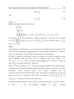
description languages with a uniform formalism are contemplated. Fig. 2 schematizes the
interactions between simulation and hardware worlds.
Q
DQ
CLK
L1
L3
L3
L3
L3
L3
L3
L2
Simulation Hardware
performance
Systemílevel
Multiílanguage
Multiíresolution
L2
L3
L1
D( . ) = Description
LA( . ) = Language
LX= Level X
Environment
Semantics
Formalism
f(D(L1), D(L2), D(L3))
Simulator Language
LA(L1)
LA(L3)
FlexibilityCoexistence
Circuitílevel
Highílevel
Fig. 2. Simulator and language in a multi-level description.
3.3 Design methodology
The design methodology outlined in this work is organized in four phases. During Phase-I
the receiver, or generally the IR-UWB system is behaviorally defined and a first high-level
model is generated. This phase is known as conception. In the case of our Energy Detection
receiver front-end this implies behaviorally modeling e.g. LNA, squaring unit, Integrate and
Dump and the Analog-to-Digital Converter (ADC). Note that in the example of figure 3 the
front-end is shown but the methodology can be applied to complete systems, even including
a dedicated backend for bit and symbol synchronization and demodulation, because VHDL
and VHDL-AMS lie on the same domain. At this abstraction level, the description still
recalls the formalism of a high-level modeling language e.g. Matlab since an electrical
interface is not defined yet and the complete system is packed onto few VHDL-AMS process
disregarding the complexity its implementation may imply. Figure 3 (Phase I) shows a
single Entity-Architecture (E&A) couple comprising a complete energy detection receiver
front-end. At this point, the model is validated by checking consistency with high-level
models developed in Matlab or in other high-level languages applied on the system-level
figures previously mentioned. Here, from the engineering point of view, the main effort
consists of defining the system operation without forcing a design partition that is mandatory
towards physical-level implementations.
85
Implementation-Aware System-Level
Simulations for IR-UWB Receivers: Approach and Design Methodology
8
()
2
()
2
Phase II
E & A mapping
(block partitioning)
Cumulative E&A
Entity
Partitioning
Refinement Modeling
Conception
Architecture
E&A
E&A
E&A
Phase I
description
High level
I & D
Sync Sync
I & D
SPICE SPICE
Phase IVPhase III
SPICE SPICE
H(s)
Modelization
Sync Sync
Fig. 3. Design methodology organized in 4 phases.
In Phase-II a first electrical signal definition is forced. We call this very important phase
partitioning. This implies rearranging the description developed during Phase-I in separate
E&A. Here we simply apply the modularity of the VHDL-AMS language on the design to get
closer to silicon implementation. Once electrical signals are defined, successive refinement
phases applied on a single block are painless provided that electrical interface is the same.
Partitioning is the key for efficiently conceiving the system and the later adjustment of
system partitioning can be problematic. Here, considering the importance of this phase, no
non-ideality are included or modeled in the simulation. The inclusion of non-ideal effects
in fact, recalls low-level implementations or, alternatively system-level parameters known to
severely impact on system-level performance. The development of a new system, intended
not being reported in the state of the art, implies only the partial knowledge of the exact
non-ideality that may compromise performance.
The ADC quantization, the AGC look-up table as well as a DAC for AGC gain analog
conversion can be all included in this phase not being properly non-ideal effects, rather
fundamental circuit features included in normal operation. Bandwidth, saturation and
blocks power consumption are not defined at this phase. System partitioning, i.e. electrical
interconnection definition, requires the knowledge of lower circuit level constraints. Since
the design is simply “rewritten”, therefore differently described with the same simulation
tool, the result must not change from Phase-I, but consistency with the previous phase needs
to be checked. Note that in Phase-II signal electrical partitioning is possible but it is not
strictly necessary, while formally only the E&A rearrangement of the conceptual operation
is required. Whether this first partitioning does not comprise electrical-level terminals, it can
be done in the next phase for each unit by refining each entity declaration.
86
Novel Applications of the UWB Technologies
Implementation-Aware System-Level Simulations for IR-UWB Receivers: Approach and Design Methodology 9
Once system partitioning is complete, the electrical interface of all the blocks in the IR-UWB
system are defined. We are now ready to increase the details in each block. For this reason,
Phase-III is called also refinement. With refinement, signals partitioned in Phase-II assume
a circuit-level meaning. Every important circuit-level non-ideality is modeled according to
continuous time or digital statements and included in the architecture. The importance
of this phase regards the identification of the non-ideal effects that impact on system-level
performance, or, if the system leads the state-of-the-art, even on its basic operation. Efforts
in the definition of the number of non-ideality of their description is an important trade-off
because very accurate models can severely impact on simulation runtime or excessive efforts
on this side can waste time and compromise the overall system-level performance inspection.
For energy detection receivers for example, modeling of compression in the front-end is
important e.g. for understanding the impact on interference rejection, but still, since the
system computes the raw energy of the UWB pulses with a squarer, this is not extremely
important. Dedicating weeks of research time on this would avoid taking important decisions
next or would block the project at its beginning, while other problems may rise during
circuit-level design or chip-level integration.
Phase-III is not only related to the inclusion of non-ideality to the previously idealized
blocks. Provided that an homogenous electrical interface derived from Phase-II in the
entity declaration of every VHDL-AMS unit is given the complete VHDL architecture can be
switched. This enables the replacement of the full VHDL-AMS modeling with transistor-level
SPICE models extracted from Cadence Front-end to Back-end or IC Station (Mentor Graphics)
other front-end circuit design tools. The description can be also extracted from layout.
This Substitute-and-Play (S&P) philosophy allows the identification of the impact of blocks
refinement on system-level performance figures. This is very important because it permits
architectural analyses by intelligently exploring all the possibilities without focusing on a
single abstraction level. Here, a heterogeneous multi-level description can help understanding
faster the problems that may arise when solid-state circuits are tested. Provided that
refinement is intelligently run, performance e.g. on ranging, demodulation, synchronization,
transceiver packet exchange, power consumption, can be forecasted and decision taken
whether constraints are not met.
IR-UWB demands time-domain simulations and a complete refined system, even if not for
all its blocks, can require very high runtimes especially when statistical tests are executed.
Notwithstanding the computational power of workstation and servers keeps increasing as
well as code parallelism in software, due to the short duration pulses high simulation accuracy
is required and a complete 10 or 100 s packet exchange simulation can require days or even
more. This applies also e.g. for PLL, where full SPICE level time-domain simulations are
impractical (and in this context also inaccurate) Lai et al. (2005). Moreover, it can result that the
effect of some circuit-level blocks severally impacts on system-level performance but cannot
be neglected in the description. Therefore, we define a successive Phase-IV, called modeling or
back-annotation, that aims at the inclusion of the relevant circuit-level non-ideality extracted
from the transistor-level description of Phase-III. This can be accomplished in two different
ways. The already modeled parameters are refined based on pure circuit level simulation, or,
if the non-ideality discovered during Phase-III was not included previously the architecture is
redesigned by keeping the same entity definition. The refined models can be used in Phase-III
for running again simulations and obtaining further results.
The full design methodology is applied on the I&D unit of our Energy Detection receiver
case study as an example. Next paragraph will focus on the design of the block and all
87
Implementation-Aware System-Level
Simulations for IR-UWB Receivers: Approach and Design Methodology
10
the hypothesis used for its conceptualization will be explained and identified in the outlined
methodological key.
4. S&P contextualization: The I&D block design
Fig. 4 shows also the partitioned entity of the I&D and the entity declaration structure. At the
highest abstraction level, the I&D electrical boundary is not defined and simply implements
the math function
x(t )dt, where x(t) is input signal. x(t) has not a physical counterpart
nor it is single-ended or differential and integration output is a quantity that is neither
voltage nor a current. A control signal is implicitly defined among the other high-level
statements that control the computation of the formula. This integrator has been included in
the high-level model and a first consistency check with a Matlab model has been completed.
When description enters Phase-II, some circuit level properties must be considered. These are
mainly related to 1) power supply, 2) control signals, 3) input and output electrical features
(single-ended or differential, AC or DC coupled, current or voltage). By satisfying these
constraints, valid for this specific case, the electrical interconnection boundary can be defined.
The I&D is a pure analog unit, that has to cope with relatively high frequency signals
2
.
Therefore, this block is not critical from the RF point of view and a single power supply
and ground connection pin can be considered. Notwithstanding this, the block is critical at
system-level. In the case of the LNA for example, having multiple power supplies can help
reducing inductance parasitic and, depending on circuit-level design, it can be fundamental
for matching. Therefore, modeling multiple power supply pins can be useful even at this
abstraction level, and the problems that may arise can be directly tackled here rather than
successively, when the floor plan is defined and circuit blocks placed down. A very first
constraint we had in the design on the energy detection receiver was that it had to be fully
differential, therefore fully differential input and outputs were assumed, in fig. 4 the couples
Inp-Inm and Out_intp-Out_intm, in particular DC coupled voltage signals. For integration
control signals the discussion is more complex because the use of a single ended or a
differential signal (one, vs. two terminals) depends on the internal implementation of the unit.
Homogeneously, we assume also perfectly differential voltage signals Controlp-Controlm.
In this very first implementation we assume that integrator is the gm-C structure depicted in
fig. 4. The transconductor transforms the input voltage into differential current and charges
a load capacitor C. When control signal Controlp-Controlm is active integration is run,
while when it toggles to ’0’ integration is reset. The biasing circuit is connected to V
bia s1
,
V
bia s2
and to V
bia s3
, it consists of two self-biasing stages that generate the required voltages
for both transconductor and Common Mode Feedback Network (CMFB), not shown here for
sake of brevity. According to the state-of-the-art simpler integrator structures are possible and
they can be single ended and much simpler than those depicted here Lee & Chandrakasan
(2007). At this point, the target was the replacement of a BiCMOS integrator by then used in
a first implementation Stoica et al. (2005) with a lower cost CMOS integrator. Note that at this
point the I&D architecture boundary has been fully defined. From an electrical point of view
this enables the VHDL architecture switching among different Phase-III domain models. For
example, a VHDL-AMS behavioral model, with the given electrical interface can be painlessly
substituted with the equivalent circuit-level or layout-description.
2
Note that after squaring, the useful portion of the spectrum of a UWB signal of bandwidth B is at
baseband,
[0, B/2], e.g. for a standard UWB pulse having a 500 MHz bandwidth, this corresponds to
operating in the band 0-250 MHz.
88
Novel Applications of the UWB Technologies
Implementation-Aware System-Level Simulations for IR-UWB Receivers: Approach and Design Methodology 11
Inp
Inm
Inp
Inm
Inp
Inm
Interface nodes
Internal nodes
Phase II
if selection=’1’ use vo’Dot == K*vin; else vo=0.0; end use;
Entity
Architecture
Phase IV
Entity
Phase III − TL
Phase I
process
begin
end process;
energy’Dot <= squared*K;
Entity
Architecture
if selection=’1’ use
A*vin−B*vo1−C*vo1’Dot==0;
D*vo1−E*vo−F*vo’Dot==0;
else vo1 == 0.0; vo = 0.0; end use;
Architecture
Entity
vo
vin
GndVdd
I & D
Out_intmOut_intp
Controlm
Controlp
GndVdd
Out_intmOut_intp
Controlm
Controlp
GndVdd
selection
vo
vin
I & D
I & D
I & D
I & D
IRíUWB RX
Architecture
selection
Out_intp Out_intm
Controlm
Controlp
UWB_in
Data_out
LV
LV
LV
LV
Vcmfb
CMFB
C
Outp
Outm
Vbias1
Vbias2
Inp
Vin
Controlm
Inm
Vdd
Gnd
Vbias3 Vdd
Out_intm
Out_intp
Voutd
LV
LV
LV
LV
LV
Transconductance Amplifier Integration switches
Controlp
Outm
Outp
Vcmfb
Gnd
Fig. 4. I&D circuit at the circuit-level design and partitioning level.
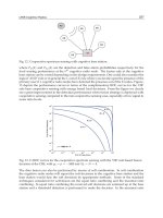
With circuit-level simulation the AC behavior of the I&D can be easily extracted. This is
reported here on fig. 5 from Crepaldi et al. (2007). The integrator operates from 1 MHz to
1 GHz, has an additional low-pass transfer function, and not ideally infinite DC gain. The
second pole at high frequency is due to parasitics of the devices. Note that the useful part
of the UWB signal is concentrated from 0 to 250 MHz for a 500 MHz pulse and the behavior
of the integrator at very high frequency is not fundamental. The non-infinite DC gain is a
loss therefore limiting the maximum length of the integration window. At this point, this AC
model can be included in the Phase-III VHDL-AMS models to speed up simulation time. Note
that by including the AC model only non-linearities and saturation of the transconductor are
not accounted for. This is a clear example of the mandatory requirement of Phase-IV, that is
an intelligent inclusion of the relevant non-ideality derived from transistor-level design. In
the case the required system-level simulation explicitly requires accounting for this non-ideal
effect, then, the backannotation shall be enriched, or alternatively the full circuit shall be
included and other blocks non-ideality deactivated to speed-up simulation time. Before
applying the substitute-and-play approach, consistency with ideal (Phase-II) and VHDL-AMS
models has been checked. As shown in fig. 5, the backannotated model and the AC circuit
simulation of Phase-III match.
89
Implementation-Aware System-Level
Simulations for IR-UWB Receivers: Approach and Design Methodology
12
Fig. 5. AC response of the I&D circuit and Phase-II and III models Crepaldi et al. (2007). The
IDEAL and VHDL-AMS models overlap.
The connection of transistor level descriptions with ideal blocks can require specific
considerations, not only related to the modeling language itself but on the electrical features
resulting from blocks interfacing. Take for example a fully ideal Phase-II model of the
squarer. A possible VHDL-AMS description can include only the simultaneous statement
vsquare==K
*
vin
**
2.0;, where square and vin are across quantities defined on two
couples of differential terminals. If this is the case, then input and output impedance of the
squarer is completely disregarded. If the squarer modeled according to this simple statement
is connected to the I&D the resulting integration voltage would be compromised because
common mode voltage is disregarded. Therefore, in such cases the inclusion of a boundary
element is fundamental for brigding the ideal world to a full custom electrical interface. These
boundary elements are inherently included in the surroundings units. In this work, proper
boundary elements, operating on the DC level of vin have been included.
Fig.6 shows a transient simulation of the integrators during three different modeling phases
II, III and IV. Notwithstanding a gain mismatch output is still energy, that is the integral of the
squared signal.
5. System-level simulations and results
One very interesting feature of Impulse-Radio UWB regards the possibility of determining
the pulses time of flight, that is, the distance between two transceivers. Since UWB pulses are
very short, the accuracy with which distance can be estimated can be very high. For example,
recent receivers are designed with fine synchronization circuits reaching accuracies of few
90
Novel Applications of the UWB Technologies
Implementation-Aware System-Level Simulations for IR-UWB Receivers: Approach and Design Methodology 13
Fig. 6. Transient response of the I&D circuits obtained from different modeling phases
Crepaldi et al. (2007).
millimeters Chu et al. (2011). Pulse radio was thought also to serve localization purposes
even in space applications Ni et al. (2010). IR-UWB can be easily applied to biomedical
devices because pulses are reflected differently depending on dielectric properties mismatches
among different mediums. This enables applications in Breast Cancer Detection and wireless
biometric parameters sensing. Here, we applied the methodology to Bit-Error-Rate tests
for wireless link quality inspection, and to Two-Way-Ranging related to ToF estimation
performance.
Figure 7 shows a graphical representation of the effect of the I&D substitution on our
energy detection IR-UWB system. The figure shows also a graphical representation of the
TWR mechanism implemented between two transceivers
3
. Two-Way-Ranging is a packet
exchange mechanism that is based on the transmission of two packets, a request packet and
an acknowledge packet between two transceivers A and B. The Time-of-Flight is calculated
at the transceiver B, after having received the acknowledge packet from transceiver A. The
ToF calculation is based on the determination of the exact leading edge of the UWB pulses
with a proper synchronization algorithm. A very common synchronization algorithm, also
called window integrator, is based on the determination of the time when the sampling of the
maximum UWB energy occurs. It is based on an integration window shift within a fixed pulse
repetition period. The shift is realized by a dedicated DLL and phase selector that sequentially
shift the control signal of the I&D. After a full exploration within the Pulse Repetition Interval
(PRI) the clock phase corresponding to maximum energy is selected. The accuracy of the
algorithm depends on the integration window shift, that for coarse synchronization can be
3
Note that other ranging schemes are possible, for example in Ni et al. (2010) Time-Difference-Of-Arrival
(TDOA) is used.
91
Implementation-Aware System-Level
Simulations for IR-UWB Receivers: Approach and Design Methodology
14
on the order of 5 ns or for fine synchronization even less than 1 ns. Here we applied this
windowed integrator for both coarse and fine synchronization. Transceiver B system clock
phase is different with respect to transceiver A, therefore the acknowledge packet must
include information on both the processing time offset of TRX A and the synchronization
phase used for detecting the maximum energy. Transceiver B, processes this information and,
according to its synchronization phase, calculates the ToF, therefore distance. Details about
the full mechanism can be found in Casu et al. (2008).
Bit-Error-Rate is determined in presence of Additive White Gaussian Noise (AWGN). Its
determination implies the inclusion of the Salleh-Valenzuela UWB channel model in the
simulation environment with a VHDL-AMS formalism IEE (2004). Natively, the model is
implemented in Matlab and here its VHDL-AMS description is based on text files with
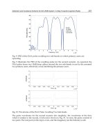
rendered saved data samples issued with a constant time step. Fig. 8 shows the effect of
Ideal
Transmitter
LNA VGA
Antenna Switch
( )
2
I & D ADC
E /N
b 0
BER
real distance (m)
A
B
12
N
clk
T
OF,1
T
OF,2
TT
01
1
2
SPICE
Transmitter
LNA VGA
Antenna Switch
( )
2
ADC
Boundary interface
Ideal
B
A
estimated distance (m)
I & D
1, 2 = Request, Ack packets
N = Fixed processing time
clk
A, B = Transceiver A and Transceiver B
OF,1
Multiílanguage
Simulator
VHDLíAMS/VHDL/SPICE
T , T = time of flight (same CLK)
OF,2
Fig. 7. Deactivation of non-ideal effects during system-level simulation and
Two-Way-Ranging.
Phase-III integrator on the BER performance of the system Crepaldi et al. (2007) as a function
of E
b
/N
0
(proportional to Signal-to-Noise Ratio). The BER curve is slightly shifter because
the pol e2 of the integrator additionally filter input noise out of the squarer. If other blocks are
implemented at transistor-level then, noise filtering increases. The results demonstrate that
this design methodology permits the determination of transistor-level non-ideality at higher
abstraction level.
With the Salleh-Valenzuela channel VHDL-AMS model TWR ranging simulations are also
possible. Detailed TWR simulation results are reported in Casu et al. (2008). Two instances
of the same IR-UWB transceiver schematized in 1 have been included in the environment
92
Novel Applications of the UWB Technologies
Implementation-Aware System-Level Simulations for IR-UWB Receivers: Approach and Design Methodology 15
0 2 4 6 8 10 12 14
10
í4
10
í3
10
í2
10
í1
10
0
E
b
/N
0
(dB)
BER
Ideal integrator
ELDO Integrator
Fig. 8. Bit Error-Rate associated to the circuit-level I&D compared to the ideal system
Crepaldi et al. (2007).
as well as specific scripts for enabling batch simulations execution. Channel is residential
Line-Of-Sight (LOS) with the recommended path loss. The simulation environment sets its
parameters with a parametric constant that models TRX distance. After 10 TWR packet
exchanges we can obtain the effect of the I&D refinement on the localization performance
of the system Crepaldi et al. (2007). With an ideal integrator at 9.9m distance, the
estimated distance is 10.10m and 11.16m with variance 0.49m and 0.10m, for the Phase-II and
transistor-level Phase-III models. Thanks to these inherent transient simulations results, the
analysis of these two results permits the identification of the circuit blocks influenced in the
performance loss. That is, having activated a transistor-level III description, enables the effects
of other ideal blocks to influence performance. From the analysis it results that the reason for
such a high variation in the estimated distance for Phase-III transistor level implementation
depends on the operation of the AGC. The presence of a slightly non-ideal effect on the
I&D “excites” the ideal AGC and a incorrect gain adjustment is provided. The incorrect
amplification imposed by the AGC loop causes the squared signal to be out of the integrator
input range and a lower output voltage is obtained. This causes the ADC quantization to
be less effective and the ranging algorithm implemented in the digital back-end fails by few
coarse synchronization steps.
Based on successive reasonings, other considerations are possible. The presence of a
transistor-level block among other ideal blocks can lead to erroneous simulation conditions.
For example, an LNA simply modeled with a perfectly linear amplifier V
out
= GV
in
, where
G is voltage gain, V
out
and V
in
are across quantities defined on input and output terminals,
does not include saturation. Due to automatic and autonomous system-level operation, an
erroneous or partial modeling of some of the other blocks, can force, for example, a gain G
on the LNA that leads to output voltage exceeding the allowed signal swing, e.g. 10 times
bigger than supply voltage. This problem occurs mainly because the system is conceived
93
Implementation-Aware System-Level
Simulations for IR-UWB Receivers: Approach and Design Methodology
16
starting from high level models when inputs and outputs miss a physical counterpart. Note
that this problem is irrelevant for high-level Matlab simulations in which idealized systems
are proven. We conclude that for a consistent and correct system-level modeling, the inclusion
of some fundamental circuit-level parameters such as voltage and power ranges limitations,
bandwidth and power consumption dependency is extremely important.
The CPU time required to run a 30 μs simulation is an important information that justifies the
presence of Phase-IV in our design methodology. As indicated in Crepaldi et al. (2007), on an
IBM-Xeon server, 4GB RAM, 3.0 GHz processor with a fixed time step of 0.05 ns, an accuracy
EPS=10e-6 and the Newton/Raphson solving algorithm, the CPU time required with the
SPICE netlist is 3 times larger than the time required using the backannotated VHDL-AMS
model and 6 times the IDEAL Phase-II description.
6. Conclusion
We have presented a methodology that allows the exploration of the impact of refinement on
system-level parameters for an IR-UWB Energy Detection system. The methodology is based
on the use of the modular formalism of VHDL, working for the design of digital circuits,
properly extended for use in analog continuous-time circuits with AMS extensions. The
methodology is based on the use of a multi-language, multi-resolution tool and it is organized
in four phases that generally define the main tasks required for a mixed-signal electronic
system conception. VHDL-AMS has been conceived for use outside the field of electrical
circuit, for example on fluidics, mechanics and all the possible domains governed by linear
differential equations. Scientific community endeavors are focused on the efficient integration
of any kind of system including MEMS even for IR-UWB Radio Frequency Tiiliharju et al.
(2009), smart sensors and energy harvesting powered devices. This design methodology can
be utilized also in these contexts, provided that the interface among the different domains is
correctly modeled and sufficiently enriched with implementation details. IR-UWB remains,
in fact, a valuable ULP wireless technology even for applications in smart sensors.
Based on these results, we believe that to merge both analog and digital design worlds,
one interesting topic for successive research can regard a simple, uniform and modular
mixed-signal language with a unique simulation tool for both analog and digital circuits
disregarding the math they are based on. This language shall allow on-the-fly simulation
accuracy directives embedded in each unit description depending on the nature of each block,
digital or analog, with a similar semantics. Compared to VHDL-AMS it shall robustly fill the
gap between the digital concurrent world and the analog continuous-time paradigm, instead
of keeping them separated and making them coexist. In fact, AMS remains still a modeling
language, therefore far from being used for automatic low-level synthesis as in digital VHDL
design.
7. References
Bielefeld, D., Fabeck, G. & Mathar, R. (2009). Power Allocation and Node Clustering
for Distributed Detection in IR-UWB Sensor Networks, IEEE Vehicular Technology
Conference Fall (VTC Fall), pp. 1–5.
Carbonelli, C. & Mengali, U. (2006). M-PPM Noncoherent Receivers for UWB Applications,
IEEE Transactions on Wireless Communications 5(8): 2285–2294.
94
Novel Applications of the UWB Technologies
Implementation-Aware System-Level Simulations for IR-UWB Receivers: Approach and Design Methodology 17
Casu, M., Crepaldi, M. & Graziano, M. (2008). A VHDL-AMS Simulation Environment for an
UWB Impulse Radio Transceiver, IEEE Transactions on Circuits and Systems I: Regular
Papers 55(5): 1368–1381.
Chu, T S., J., R., Chang, S., T., M., C., D. & Hossein, H. (2011). A Short-Range UWB
Impulse-Radio CMOS Sensor for Human Feature Detection, IEEE International
Solid-State Circuits Conference (ISSCC), Digest of Technical Papers, pp. 294–296.
Crepaldi, M., Casu, M., Graziano, M. & Zamboni, M. (2007). An effective AMS Top-Down
Methodology Applied to the Design of a Mixed-Signal UWB System-on-Chip, Design,
Automation Test in Europe Conference Exhibition, pp. 1–6.
Crepaldi, M., Li, C., Dronson, K., Fernandes, J. & Kinget, P. (2010). An Ultra-Low-Power
Interference-robust IR-UWB Transceiver Chipset Using Self-synchronizing OOK
Modulation, IEEE International Solid-State Circuits Conference (ISSCC), Digest of
Technical Papers, pp. 226–227.
Daly, D., Mercier, P., Bhardwaj, M., Stone, A., Voldman, J., Levine, R., Hildebrand, J.
& Chandrakasan, A. (2009). A Pulsed UWB Receiver SoC for Insect Motion
Control, IEEE International Solid-State Circuits Conference - Digest of Technical Papers,
pp. 200–201,201a.
FCC (2002). Revision of Part 15 of the Commission’s Rules Regarding Ultra-Wideband
Transmission Systems, Report and order, adopted February 14, 2002, released July
15, 2002.
Gorlatova, M., Kinget, P., Kymissis, I., Rubenstein, D., Wang, X. & Zussman, G. (2010). Energy
Harvesting Active Networked Tags (EnHANTs) for Ubiquitous Object Cetworking,
IEEE Wireless Communications 17(6): 18–25.
Han, G. & Sanchez-Sinencio, E. (1998). CMOS Transconductance Multipliers: A Tutorial,
IEEE Transactions on Circuits and Systems II: Analog and Digital Signal Processing
45(12): 1550–1563.
IEE (2004). IEEE 802.15.4a Channel Model - Final Report.
URL: />IEE (2007). IEEE 802.15 WPAN Low rate Alternative PHY Task Group 4a (TG4a).
URL: />IEEE (2007). P1076.1/D3.3, Approved Draft Standard VHDL Analog and Mixed-Signal
Extensions (Revision of IEEE Std 1076.1-1999).
Lai, X., Wan, Y. & Roychowdhury, J. (2005). Fast PLL Simulation Using Nonlinear VCO
Macromodels for Accurate Prediction of Jitter and Cycle-slipping due to Loop
Nonidealities and Supply Noise, IEEE Asia and South Pacific Design Automation
Conference, Vol. 1, pp. 459–464 Vol. 1.
Lecointre, A., Dragomirescu, D. & Plana, R. (2010). Largely Reconfigurable Impulse Radio
UWB Transceiver, Electronics Letters 46(6): 453–455.
Lee, F. & Chandrakasan, A. (2007). A 2.5nJ/bit 0.65V Pulsed UWB Receiver in 90nm CMOS,
IEEE Journal of Solid-State Circuits 42(12): 2851–2859.
Ni, J., Arndt, D., Ngo, P., Phan, C., Dekome, K. & Dusl, J. (2010). Ultra-wideband
Time-Difference-Of-Arrival High Resolution 3D Proximity Tracking System, IEEE
Position Location and Navigation Symposium (PLANS), pp. 37–43.
Stoica, L., Rabbachin, A., Repo, H., Tiuraniemi, T. & Oppermann, I. (2005). An Ultrawideband
System Architecture for Tag Based Wireless Sensor Networks, IEEE Transactions on
Vehicular Technology 54(5): 1632–1645.
95
Implementation-Aware System-Level
Simulations for IR-UWB Receivers: Approach and Design Methodology
18
Tiiliharju, E., Koivisto, T., Maunu, J., Chekurovy, N. & Tittoneny, I. (2009). Ultra-wideband
CMOS-MEMS Radio, IEEE International Conference on Ultra-Wideband, pp. 102 –106.
Verhelst, M. & Dehaene, W. (2008). A Flexible, Ultra-Low-Energy 35 pJ/Pulse Digital
Back-End for a QAC IR-UWB Receiver, IEEE Journal of Solid-State Circuits
43(7): 1677–1687.
Wang, X. Y., Dokania, R. K. & Apsel, A. (2011). PCO-Based Synchronization for Cognitive
Duty-Cycled Impulse Radio Sensor Networks, IEEE Sensors Journal 11(3): 555–564.
96
Novel Applications of the UWB Technologies
5
Time-Hopping Correlation Property and Its
Effects on THSS-UWB System
Zhenyu Zhang
1,2
, Fanxin Zeng
2
, Lijia Ge
2
and Guixin Xuan
2
1
College of Communication Engineering, Chongqing University
2
Chongqing Communication Institute
China
1. Introduction
Ultra wideband (UWB) is a promising technology for short-range wireless communications
since it potentially combines the reduced complexity with low power consumption, low
probability of detection/intercept (LPD/LPI) and immunity to multipath fading (Scholtz,
1993; Win & Scholtz, 1998; Win & Scholtz, 2000). The successful development of UWB
technology strongly depends on the advancement of efficient multiple-access techniques. A
typical multiple-access format of UWB is time-hopping spread spectrum ultra wideband
(THSS-UWB) where data are transmitted by using pulse position modulation (PPM)
(Scholtz, 1993) or pulse amplitude modulation (PAM) (Le Martret & Giannakis, 2000) at a
rate of many pulses per data symbol. Both of PPM and PAM require good properties of TH
sequences.
In terms of TH correlation properties, the known constructions of TH sequences can be
mainly classified into two categories, namely aperiodic TH sequences and periodic TH
sequences. For aperiodic TH sequences, the chaotic pulse-position modulation (CPPM)
which was designed for the transmission of binary information (Sushchick et al, 2000) and
the pseudo-chaotic time hopping (PCTH) which exploited the symbolic dynamics of a
chaotic map at the transmitter (Maggio et al, 1999; Maggio et al, 2001) were proposed,
respectively. In addition, an alternative use of pseudo-chaotic dynamics was proposed as an
encoder for the binary data stream while data-independent TH sequences were used to
guarantee ease of synchronization and decidability (Erseghe & Bramante, 2002). For periodic
TH sequences, the related analyses can be found in the corresponding literatures (Chu &
Colbourn, 2004; Corrada-Bravo, 1999; Erseghe, 2002a; Erseghe, 2002b; Iacobucci & Di
Benedetto, 2001; Iacobucci & Di Benedetto, 2002; Scholtz et al, 2001). These sequences can be
considered as the extensions of existing frequency-hopping (FH) sequences and all of them
have good TH correlation properties. In these TH sequences, quadratic congruence code
(QCC) (Scholtz et al, 2001) is the best one in terms of TH correlation properties since QCC
satisfies
max
2S and
max
4C
, where
max
S denotes the maximal TH auto-correlation
function (ACF) sidelobe and
max
C denotes the maximal TH cross-correlation function (CCF)
values. For aperiodic and periodic TH sequences, the theoretical bound, namely the relation
between four parameters of sequences period L, the number of time slots N, TH sequences
Novel Applications of the UWB Technologies
98
family size
u
N and maximal TH correlation function values
max
C (or
max
S ), plays an
important role in construction schemes. So far, several theoretical bounds had been
obtained, such as Johnson bounds and new upper bounds (Gao & Chang, 2006; Scholtz et al,
2001).
This chapter mainly focuses on constructions and theoretical bounds of periodic TH
sequences. A generalized definition of TH periodic correlation function which can be used
to analytically evaluate TH correlation properties is presented. Based on this definition, a
method to improve TH correlation properties in practical applications is proposed. By such
a method, the maximum correlation function values of TH sequences can be reduced to a
half of original values. Consequently, coincident probabilities among TH sequences
decrease. In addition, averages of TH periodic correlation function values are investigated,
and the relations between the averages and four TH parameters are formulated. From the
results, low bounds of maximal TH correlation function values are further obtained.
In terms of the obtained low bounds, the multiple access interference (MAI) of
asynchronized THSS-UWB systems is inevitable. Although orthogonal communications will
be realized when accurate synchronism is held in the whole system, the accurate
synchronization is difficult to be kept and catastrophic collisions will happen when
synchronization in the whole system fails to be perfectly kept. In this chapter, a novel of TH
sequences with zero correlation zone (ZCZ) is constructed. THSS-UWB systems employing
such sequences can be without MAI when the shifts between TH sequences are in range of
ZCZ. In other words, when MAI comes as small shifts of cross correlation, the MAI will be
eliminated since CCF values are equal to zero in range of ZCZ. As a result, orthogonal
communications can be realized while the need of accurate synchronism in whole system is
reduced. The idea of approximate synchronization and ZCZ was firstly proposed for direct
sequence (DS) in code division multiple access (CDMA) (Suehiro, 1994), and a lot of DSs
with ZCZ had been constructed (Fan, 1999; Hayashi, 2009; Hu & Gong, 2010). As for TH
sequences with ZCZ, the corresponding studies were also presented (Guvene & Arslan,
2004a; Guvene & Arslan, 2004b; Zeng et al, 2011). Different from the known constructions of
ZCZ TH sequences, the method proposed in this chapter can provide a more flexible choice
of TH parameters.
Based on the analyses of TH correlation properties, multiple access performance of THSS-
UWB systems is presented. So far, most studies on MAI assumed that the interference was a
zero-mean Gaussian random variable, namely Gaussian approximation (Canadeo et al, 2003;
Durisi & Benedetto, 2003; Hu & Beaulieu, 2003; Mireles, 2001; Scholtz, 1993; Win & Scholtz,
1998; Win & Scholtz, 2000; Zhao & Haimovich, 2002). Multiple access communication
performance using UWB waveforms with TH-PPM and DS-BPSK modulations was studied
(Canadeo et al, 2003), where the analyses used a fixed sequence, namely Gold codes. Based
on Gaussian quadrature rules (GQR) and a characteristic function (CF) technique, two new
methods to evaluate the bit error rate (BER) performance of THSS-UWB in the presence of
MAI and additional white Gaussian noise (AWGN) channel were proposed (Durisi &
Benedetto, 2003; Hu & Beaulieu, 2003), respectively. However, they still considered TH
sequences as independent random variables, which will lose the practical characteristics of
TH sequences. As a result, the effects of TH correlation properties on the multiple-access
performance of THSS-UWB systems are ignored. In order to analyze the practical effect of
TH sequences, this chapter derives analytical expressions of the relations between MAI
Time-Hopping Correlation Property and Its Effects on THSS-UWB System
99
values and TH correlation function values, which can be used to evaluate the BER
performance in the presence of MAI.
The organization of this chapter is as follows. After the introduction, the definitions of TH
periodic correlation function are provided in Section 2. The definitions are used to obtain
theoretical bounds of TH sequences in Section 3 and improve TH correlation properties in
Section 4. A novel family of TH sequences with ZCZ is obtained in Section 5. Based on TH
correlation properties, the analyses of MAI are presented in Section 6. Finally, Section 7
summarizes the results.
2. TH correlation properties
In this section, we begin with the PPM model of THSS-UWB systems to understand how TH
sequences work. We then analyze the correlation property of TH sequences in THSS-UWB
systems.
2.1 PPM model of THSS-UWB systems
The PPM model is a kind of hopping format which is studied widely in THSS-UWB
systems. In PPM model, the transmitted signal for user i may be expressed as
() ()
()
()
/
() ( )
L
S
ii
i
fc
k
kN
k
St wtkT cT d
(1)
where ()w represents the transmitted monocycle waveform and
()
()
L
i
k
c denotes a TH
sequence assigned to user i , where the notation
()
L
denotes a modulo L operation. The
TH sequence
()
()
L
i
k
c is periodic with period (or sequence length) L and each sequence
element is an integer in the range of
()
()
0
L
i
h
k
cN. The notation
f
T denotes frame time (or
pulse repetition time) and
c
T is TH slot time,
f
c
TNT
, usually 1
h
NN
, which
represents the number of TH time slots in a frame time. The notation
is the data shift
time. The data sequence
()i
m
d of user i is a binary stream. One symbol may be conveyed
by
s
N monocycles. The notation x
denotes the integer part of x .
According to the equation (1), we can see that the properties of TH sequences will play a key
role in THSS-UWB systems. They ensure that UWB becomes a multiple access system and
these sequences have a significant effect on synchronization and channel estimation. Fig. 1
shows how TH sequences work in THSS-UWB systems. In Fig. 1,
5
(1)
()
{2,0,1,4,3}
k
c and
5
(2)
()
{2,4,3,0,1}
k
c represent two TH sequences, respectively, where 5NL
. The two
TH sequences control the position of pulse of user 1 and user 2, respectively. In addition,
Fig. 1 shows that two collisions between two TH sequences emerge when some shift
happens in a period. For more simplicity to be understood, time slots that happened to
collision are marked with double-head arrow in Fig. 1.
Novel Applications of the UWB Technologies
100
Fig. 1. The collision situation between two TH sequences (two users)
2.2 Definitions of TH periodic correlation function
For TH sequences, TH correlation properties are described by TH correlation function. In
terms of chip synchronism (where shift
f
lT
and 0 1lL
), TH periodic correlation
function was defined as follows.
Definition 1 (Iacobucci & Di Benedetto, 2002): Let
()
()
L
i
k
c and
()
()
L
j
k
c denote two time
hopping sequences with period
L , and then the Hamming TH periodic correlation function
with shift
l is given by
1
()
()
() ( )
0
() [ , ]
LL
L
j
i
ij
kkl
k
Hl hc c
, 0 1lL
, (2)
where
()
()
1,
() ( )
()
()
[, ]
() ( )
()
()
0,
() ( )
j
i
cc
kkl
j
i
LL
hc c
kkl
j
i
LL
cc
kkl
LL
.
According to the equation (2), we can see that Definition 1 requires 0 1
lL
and
f
lT ,
that is, the frame time
f
T belonging to transmissions of different users must be
synchronized. Hence, Definition 1 is the same as the definition of FH correlation function.
Specially, we have 0
l
when codeword synchronism is held in whole system.
In order to help to understand the collisions situation between the sequences, we give Fig. 2
which is array representation of sequences
{0,3,8,10,5,1,6,9,2,4,7} with 11LN
. In Fig.
2, columns and rows indicate time frames and time slots, respectively. Also, each column
has a unique one (black box) indicating the time slot on which we transmit according to the
sequence
()
()
L
i
k
C . Fig. 3 shows how Definition 1 works in the case of chip synchronism. In
Fig. 3, we employ QCC sequence as an example. For QCC sequence,
()
2
()
()
L
i
p
k
cki
, where
p
is a prime,
LP , the number of users 1
u
NP
, 0 1kL
and 0 1iP
. Let 11p ,
then
11L and 10
u
N
. Fig. 3 shows the place of the maximum TH CCF value between
11
(3)
()
k
c and
11
(5)
()
k
c when 1l
.
c
T
1user
f
T
2user
4
3
21
0
2
0
1
4
4
3
2
0
12
55 25( )
c
NL T
17( )
c
T
35 2
laNb
Time-Hopping Correlation Property and Its Effects on THSS-UWB System
101
Fig. 2. Array representation of the sequence {0,3,8,10,5,1,6,9,2,4,7} , where 11LN
Fig. 3. The illustration of the maximum CCF value between
11
(3)
()
k
c and
11
(5)
()
k
c of QCC
sequences when 1l
, where collisions are denoted by a cross
and
max
2C
Compared with chip synchronism and codeword synchronism which are difficulty to be
kept, the asynchronism format is more interesting. Then, we consider a more general
definition of TH periodic correlation function which can be used to analytically evaluate the
TH correlation properties in codeword synchronism, chip synchronism and asynchronism
in the whole system.
Definition 2: Let
()
()
L
i
k
c and
()
()
L
j
k
c denote two TH sequences with the period L , and then
TH periodic correlation function with shift l can be expressed as
()
ij
Cl A B
, (3)
where
()
()
{| ( ) }
L
i
NL
ka
AxxkNc
,
()
()
{| ( ) }
L
j
NL
k
BxxkNc b and 0 , , 1abk L
. The
notation
x represents the number of the elements in set x and AB
indicates the
intersection between two sets of
A and B. The symbol l denotes shift and satisfies
laNb. Then, we have 0 1lNL
.