Behaviour of Electromagnetic Waves in Different Media and Structures Part 6 pdf
Bạn đang xem bản rút gọn của tài liệu. Xem và tải ngay bản đầy đủ của tài liệu tại đây (1.32 MB, 30 trang )
Detection of Delamination in Wall Paintings by Ground Penetrating Radar
137
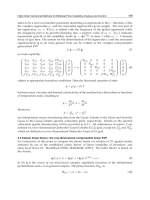
Fig. 26. In-situ detection of delamination in wall paintings in Lashao Temple
As a rule of thumb, the relative dielectric constant of mural plaster is about 1.5, so that
electromagnetic wave travels in plaster layer at the speed of about 2.45×10
8
m/s (245 m/μs
or 245 mm/ns). In the dialog box of parameter setting, the window of two-way travel time is
input as 3 ns, which is equal to set the effective detection depth as 36.75 cm, the sampling
frequency is chosen as 142 GHz, the interval of impulse triggering time is set as 0.1 s, and
the function of automatic stacking is turned on. During the operation of signal processing,
the following four filters are loaded: DC Removal, Substract Mean Trace, Band Pass, and
Running Average.
Fig. 27. Presentation of GPR profile H
3
Behaviour of Electromagnetic Waves in Different Media and Structures
138
It is shown in the interpretation results (Fig. 27, Fig. 28, Fig. 29) that the delamination in wall
paintings in the detection region is mainly located at the lower left corner, which is in
consistence of the area where the loss of mural plasters is serious. In addition, delamination
is also serious in the lower right corner and the upper part of detection area. Taking into
account that the vertical resolution of RAMAC ground penetrating radar is about 5 mm,
delamination in detection area should be more serious (Fig. 30).
Fig. 28. Presentation of GPR profile H
5
Fig. 29. Presentation of GPR profile V
1
Detection of Delamination in Wall Paintings by Ground Penetrating Radar
139
Fig. 30. Comprehensive interpretation of delamination in wall paintings, marked by arc
4. Conclusion
Focusing on the propagation of high frequency pulse electromagnetic waves in layered
lossy and dispersive medium and after the physical forward modeling experiment, this
chapter has successfully located delamination in polished wall paintings by wall coupling
antennas using RAMAC ground penetrating radar. It is shown that the ultra-wide band
ground penetrating radar is capable of detecting delamination in vertical resolution of
about 5 mm when it is equipped with a transmitting antenna of 1.6 GHz central
frequency.
5. Acknowledgment
This project is jointly sponsored by State Administration of Cultural Heritage, People's
Republic of China in Cultural Heritage Conservation Science and Technology Foundation
(No.200101).
The author wishes to thank Dr. Tao YANG of Lanzhou University and Xuebing BAI of
Beijing Xing Heng Yun Science & Trade Co., Ltd. , China for their collaboration and support
with the case work. The author is also indebted to Professor Yi SU of National University of
Defense Technology, China and Professor Zheng'ou ZHOU of University of Electronic
Science and Technology of China for their kind and helpful comments in the preparation of
this chapter.
The author is grateful to Professor Zuixiong LI & Dr. Liyi ZHAO of Dunhuang Academy
and all the staff of Conservation Institute and Technical & Service Center for Protection of
Cultural Heritage helped to carry out the lab test and the field test, they are greatly
acknowledged for their invaluable logistic support.
Behaviour of Electromagnetic Waves in Different Media and Structures
140
6. References
[1] Z. Li, W. Wang, X. Wang, J. Chen, and G. Qiang Ba, Report on Wall Painting Conservation
and Restoration Project of Potala Palace, Tibet. Beijing, China: Cultural Relics Press,
2008. ISBN 9787501024704.
[2] W. Wang, Z. Ma, Z. Li, T. Yang, and Y. Fu, Consolidating of Detached Murals through
Grouting Techniques, Sciences of Conservation and Archaeology, vol. 18, no. 1, pp. 52-
59, Mar. 2006. ISSN 1005-1538.
[3] W. Wang, L. Zhao, T. Yang, Z. Ma, Z. Li, and Z. Fan, Preliminary Detection of Grouting
Effect on Delaminated Wall Paintings in Tibet Architecture, Chinese Journal of Rock
Mechanics and Engineering, vol. 28, supp. 2, pp. 3776-3781, Sep. 2009. ISSN 1000-
6915.
[4] L. Kong, and Z. Zhou, A Effective Method of Improved Resolution for Imaging of
Subsurface Ground Penetrating Radar, Signal Processing, vol. 18, no. 6, pp. 505-508,
Jun. 2002. ISSN 1003-0530.
[5] Y. Su, C. Huang, and W. Lei, Theory and Application of Ground Penetrating Radar. Beijing,
China: Science Press, 2006. ISBN 7030172833.
[6] Z. Li, T. Yang, and W. Wang, Forward Replica Modeling for Detection of Delamination
in Wall Paintings with Ground Penetrating Radar, Journal of Engineering Geology,
vol. 17, no. 5, pp. 675-681, Oct. 2009. ISSN 1004-9665.
[7] Z. Li, T. Yang, W. Wang, and W. Chen, Detection of Delamination in Tibetan Wall
Paintings by Using Ground Penetrating Radar, Journal of University of Electronic
Science and Technology of China, vol. 39, no. 6, pp. 865-870, Dec. 2010. ISSN 1008-
8105.
8
Interaction of Electromagnetic
Radiation with Substance
Andrey N. Volobuev
Samara State University
Russia
1. Introduction
1.1 Distribution of Electromagnetic Field Momentum in dielectrics in stipulation of
self-induced transparency
Interaction of quantums of electromagnetic radiation with substance can be investigated
both from a wave position, and from a quantum position. From a wave position under
action of an electromagnetic wave there are compelled fluctuations of an electronic orbit and
nucleus of atoms. The energy of electromagnetic radiation going on oscillation of nucleus
passes in heat. Energy of fluctuations of an electronic orbit causes repeated electromagnetic
radiation with energy, smaller, than initial radiation.
From a quantum position character of interaction is more various. Interaction without
absorption of quantums is possible: resonant absorption, coherent dispersion. The part of
quantums is completely absorbed. Quantums can be absorbed without occurrence
secondary electrons. Thus all energy of quantums is transferred fonons - to mechanical
waves in a crystal lattice, and the impulse is transferred all crystal lattice of substance. At
absorption of quantums can arise secondary electrons, for example, at an internal
photoeffect. Absorption of quantums with radiation of secondary quantums of smaller
energy and frequency is possible, for example, at effect of Compton or at combinational
dispersion.
All these processes define as formation of impulses of electromagnetic radiation in
substance, and absorption of radiation by substance.
1.2 Coordination of the electromagnetic impulse with the substance
Firstly, consider the one-dimensional task the electric part of electromagnetic field
momentum with the dielectric substance, which posses a certain numerical concentration n
of centrosymmetrical atoms – oscillators. For the certainty of the analysis we suggest the
atom to be one-electronic. It is also agreed, that no micro current or free charge are present
in the medium. The peculiarities of interaction between magnetic aspect of momentum and
the atoms will be considered later.
We accept that there takes place the interaction of quantum of electromagnetic radiation
with nuclear electrons, thus quantum are absorbed by the electrons. By gaining the energy
of quantum the electrons shift to the advanced power levels. Further, by means of resonate
shift of electrons back, appears the quantum radiation forward. The considered medium lacks
non-radiating shift of electrons, i.d. the power of quantum is not transfered to the atom.
Behaviour of Electromagnetic Waves in Different Media and Structures
142
Thus, the absorption of electromagnetic radiation in the case of its power dissipation in the
substance, owing to SIT, is disregarded. There appears the atomic sypraradiation of
quantum. Thus, the forefront of momentum passes the power on to the atomic electrons of
the medium, forming its back front.
The probabilities of quantum's absorption and radiation by the electrons in the unity of
time, with a large quantity of quantum in the impulse, according to Einstein, can be
referred to as the approximately identical [6]. For the separate interaction of the with the
electron this very probability is the same and is proportional to the cube of the fine-
structure constant ~ (1/137)
3
[7]. Consider a random quantity – the number of interactions
of quantum with atomic electrons in the momentum. In accordance with the Poisson law
of distribution, the probability of that will not be swallowed up any quantum atomic’s
electrons (will not take place any interaction), at rather low probability of separate
interaction, is equal an exponent from the mathematical expectation of a random variable
− an average quantity of interactions
λ
of quantums and electrons in impulse, taken with
the minus
()
expp
λ
=−. Therefore, as it will be explained further, it is possible that the
intensity of non-absorbed power of impulse by the atomic electrons of the medium in it
forefront is determined by the exponential Bouguer law [3] (in German tradition - Beer
law)
0
exp( )II l
α
=−, (1.1)
where
α
– index of electromagnetic wave and substance interaction, l – length of interaction
layer, I
0
- intensity of incident wave. Thus, the intensity of atomic electron's power recoil
into impulse on its back front could be described with the help of the Bouguer law with the
negative index of absorption [8].
The index of interaction is
n
ασ
= , where
α
− effective section of atom-oscillator interaction
with the wave. Hence,
eff eff
eff
VV
lnlnVnV M MN
VV
ασ
== = = = , (1.2)
where
V
eff –
the effective volume of interaction. In defying (1.2) the right part of the formula
is multiplied and divided by the geometric volume
V, in which there is M of particles
interacting with the radiation. The ratio
eff
V
N
V
=
. The ratio of effective volume of interaction
to the geometric volume characterizes the medium possibility of electromagnetic radiation's
interaction with the atom. Hence, by exponential function in the Bouguer law (1.1) the
mathematical expectation of random variable is supposed, which subdues to the Poisson
law distribution – average variable of atoms interacting with the electromagnetic radiation
in the area of impulse influence
NM
λ
= .
Taking into account that the wave intensity is
2
2
~
E
I
H
we shall have
0
0
exp
2
EE
l
HH
α
=−
, (1.3)
Interaction of Electromagnetic Radiation with Substance
143
where
0
E ,
0
H − the amplitudes of electric and magnetic fields' strength of the impulse on
longitudinal coordinate
X = 0.
In the formula (1.3) and further the upper variables in parentheses are referred to electric
field, and lower – to the magnetic field of impulse.
By the ratio (1.2) it is possible to find
00
22
ln ln
EH
N
М
E М H
=− =−
. (1.4)
The formula (1.4) demands some further consideration. If
E<E
0
, that reflects the process of
wave absorption by atomic electrons
N>0 and classical consideration of electromagnetic
wave interaction with the atom is quite admissible. The case when
E>E
0
reflects the process
of wave over-radiation. Thus,
N<0 and variable N can not be considered as the probability
of electromagnetic wave interaction with the atom. In this case we speak about the
quantum-mechanical character of the process of interaction between the quantum and the
bi-level power system of the atom, provided that the power transition's radiation is
reversed. Variable
N in this case possess the notion of united average of filling by atom (-
1<N<1
). Due to the use of the average of filling to raise the atom and bend of its magnetic
moment in the magnetic field of the impulse, the existence of bi-level quantum system by
magnetic quantum numbers. Thus, the variable
N provides with the measure of inversion of
the system of atom-radiators by the raised atoms [2] as well as the measure of inversion of
the magnetic moment of the atom's system by magnetic quantum numbers. If
N=-1 all the
atoms occur in the basic condition [3].
Fig. 1. Dependence of volumetric density of energy of electromagnetic radiation impulse
w
(curve 1) and average on atoms of number of filling
N (curve 2) from time; 3 and 4 - points
of an excess of function
w(t)
We consider the dependence of the average of filling on the time
N(t). If to accept the
proportion of polarization of separate bi-level atom to the intensity of electric field in the
impulse, then, in accordance with the Maxwell-Bloch equations, the average by atoms of
considered volume, the filling number is proportional to the volumetric density of
electromagnetic wave power
N~w [3]. However such a monotonous dependence between
these variables can not remain on the whole extent of the impulse. Firstly, by the high
Behaviour of Electromagnetic Waves in Different Media and Structures
144
volumetric density of impulse power w, typical of SIT, when the central part of impulse
power is higher than any variable
w, there exists energetic saturation of the medium. The
average filling number thus
N=1, all the atoms are raised, fig. 1 (curve 1 - the dependence w
of time, thicker curve 2 – the considered dependence
N of time). The violation of proportion
N~w in the central part of impulse is the basic drawback of frequently used system of
Maxwell-Bloch equations for the SIT description.
Secondly, the period of variable
N relaxation is not less than 1 ns [2] that is why the
dependence
N(t) can not repeat high-frequently oscillations on both fronts of the impulse.
The dependence
N~w could characterize the proportion of average filling number and
envelope
w (curve 1) in the impulse. However, in two points of the fold (3 and 4 fig. 1) on
the sites of increase and decrease if the envelope
w the variable
22
/0wt∂∂= hence, also
22
/0Nt∂∂=. Besides, the dependence N(t) has the symmetrical character as at the SIT
impulse becomes the conservative system (there is no reverse dispersion and dissipation of
power) [2]. Therefore, it could be thoroughly concerned that on the whole extent of impulse,
except the points of curve's
N(t) fold, the condition remains
2
2
0
N
t
∂
=
∂
, (1.5)
while the dependence
N(t) has the character as shown on the fig. 1, curve 2. it could be also
highlighted the high generality of formula (1.5), which is possible for any piecewise linear
function
N(t). Thus, the points of function break are excluded, as the derivates undergo the
break.
1.3 Non-linear Schrödinger equation
One-dimensional wave equation for electric and magnetic aspects of electromagnetic field
for the considered problem is [2]
22 2
0
222 2 2
/
11
EE P
HH J
X с t с t
μμε
εε
∂∂ ∂
−=
∂∂ ∂
, (1.6)
where
or
YZ
EE EE≡≡, or
YZ
HH HH≡≡, X and t – accordingly the coordinate alongside
of which the impulse and the time are distributed,
P − polarization of substance, J – its
magnetization,
0
ε
and
0
μ
− electrical and magnetic constant,
ε
− relative static permittivity
of substance,
μ
– relative magnetic permittivity,
00
1/c
ε
μ
= – speed of light in vacuum.
We introduce the transformation of electric field intensity be formula
0
(,)
(,)exp( )
(,)
EXt
Ф Xt i t
HXt
ω
=−
. (1.7)
The function
Ф(X, t) is less rapidly changing one in time then E(X,t) or H(X,t),
ω
0
– aspect of
cyclic frequency of high-frequent oscillations of the field.
By substituting (1.7) and (1.6) we get
22 2
0
2
00 0
22 2 2 2
/
11
2exp()
P
ФФФ
i Ф it
J
Хс tt с t
μμε
ωω ω
εε
∂∂∂ ∂
−−−−=
∂∂∂ ∂
. (1.8)
Interaction of Electromagnetic Radiation with Substance
145
We estimate the relative variable of first and second items in the parenthesis of the left side
(1.8). for this purpose we would introduce the scales of variables time t and Ф
**
0
/, /Ttt ФФФ==,
where the asterisk designates dimensionless parameters. For the time scale the duration
(period) of impulse T should be logically chosen. The scale Ф
0
is chosen from a condition
that dimensionless second derivative
2*
*2
Ф
t
∂
∂
and the dimensionless function Ф* are in the
same order. Hence, the the first item in round brackets (1.8) is
2*
0
2*2
ФФ
Tt
∂
∂
, and the last one
2*
00
ФФ
ω
. Instead of impulse T period we introduce cyclic frequency of impulse
2
T
π
ω
=
. By
comparing these items, it is realized, that
22*
2*
0
00
2*2
4
ФФ
ФФ
t
ω
ω
π
∂
<<
∂
as the cyclic frequency
of impulse is far less than infrequences of field's oscillations, especially when
22
0
ωω
<< .
Similarly, it can be presented that the second item in the round brackets (1.8) is far more that
the first one.
Hence, by disregarding the small item in (1.8), we observe
2 2
0
2
00 0
22 2 2
/
11
2exp()
P
ФФ
i Ф it
J
Хс t с t
μμε
ωω ω
εε
∂∂ ∂
−+−=
∂∂ ∂
. (1.9)
By accepting vector of polarization P or magnetizing J to be directly proportional,
accordingly, to the electric and magnetic fields strength, we could derive the wave equation
from (1.6), which is possible to any form of the wave. However, there exists a physical
mechanism, which restrict the wave form. This mechanism is connected with the way of
over-radiating of electromagnetic impulse with the atomic electrons. This process is
precisely considered further.
We consider the strength of electric and magnetic fields of impulse as
[]
(,)
(,)
exp ( )
(,)
(,)
EXt
EXt
irX t
HXt
HXt
δ
=−
, (1.10)
where r and
δ
– are constants, |E (X,t)| and |H(X,t)| are the modules of functions E(X,t)
and H(X,t).
Formulas (1.4) and (1.5) reflect the offered physical model of electric and magnetic field of
impulse interaction with atoms in SIT.
Hence, taking into account (1.4) and (1.5) there is
22
00
22
ln ln
0
EH
EH
tt
∂∂
==
∂∂
. (1.11)
By transforming (1.11) we have
2
2
2
lnEE
E
tt
∂∂
=
∂∂
. (1.12)
Behaviour of Electromagnetic Waves in Different Media and Structures
146
The similar ratio can be also referred to the function |H|. These ratios should not be regarded
as the equations to define the module of electric and magnetic aspect of impulse. It is the
approximate expression of the second derivative
2
2
E
t
∂
∂
or
2
2
H
t
∂
∂
for the considered physical
model and reflects several non-linear effects of interaction between electromagnetic radiation
and substance. The approximate ratio (1.12) defines the connection of medium polarization P
with the strength of impulse electric field (similarly to the magnetization J with the magnetic
field strength), that would be considered further. The electromagnetic field impulse strengths
should be estimated from the equation (1.6) taking into account the ratio (1.12).
In accordance with (1.10),
[]
(,)
(,)
exp ( )
(,)
(,)
EXt
EXt
irX t
HXt
HXt
δ
=−−
, hence, from (1.12) we
estimate equation for the electromagnetic field impulse
2
2
0
2
2
ln
2
E
E
EE
iE
tt t
δδ
∂
∂∂
=− + +
∂∂ ∂
. (1.13)
The same ratio exists for the magnetic field also. Passing over to (1.13) to the function Ф(X,t)
by formula (1.7) and by concerning
0
PE
ε
χ
= , where χ – relative dielectric permittivity of
substance, we have
2
2
0
2
0000 0
2
ln
22 exp()
Ф
Ф
P Ф
i ФФit
tt t
δε
χ
δε
χ
ωε
χ
δω
∂
∂∂
=− − + + −
∂∂ ∂
, (1.14)
For the variable
2
2
J
t
∂
∂
by using JH
χ
= , where χ – relative magnetic permittivity of
substance, we get the ratio, similar to (1.14), except that the right part lacks
ε
0
.
The variables
0
00
0
exp( )
E
Ф it
H
ω
=−
. By comparing (1.7) and (1.10) we state
0
0
0
,
EE
ФФconst
HH
===
.
By substituting (1.14) into (1.9)
()
()
2
2
0
222
000
2
ln
1/
22
1/
Ф
Ф
ФФ
ic ФФ
t Х t
μ
ωχδ ω χδωχδ χ
ε
∂
∂∂
++ ++−=
∂∂ ∂
. (1.15)
Interaction of Electromagnetic Radiation with Substance
147
In the equation (1.15) the variable χ is meaningful to dielectric permittivity for electric and
magnetic permittivity for the magnetic aspects of electromagnetic field.
The non-linear Schrödinger equation with complicated type of linearity is received. We
introduce the signs:
0
αω
χ
δ
=+ ,
2222
00
2
ε
γ
ω
χ
δω
χ
δα
χ
δ
μ
=+ − =−
, where
1
ε
χ
μ
=+
–
relative permittivities of the substance. Hence, the equation (1.15) will be
2
2
0
2
2
ln
1/
2
1/
Ф
Ф
ФФ
ic ФФ
t Х t
μ
αγχ
ε
∂
∂∂
++=
∂∂ ∂
. (1.16)
We shall find the solution to the non-linear Schrödinger equation (1.16) as in [9]
()
()
*
0
expФФ
f
kX t i rX t
ωδ
=− −
, (1.17)
where the type of the function
()
f
kX t
ω
−
is still unknown. The variables k,
ω
and
δ
*
–
constants. By marking kX t
ζ
ω
=−, and substituting (1.17) in (1.16) and concerning
()
0
ФФf
ζ
= we get
2
2
22 2 *22 2
2
1/ 1/ 1/
ln
22
1/ 1/ 1/
df df d f
ckikrc
f
rc
f
dd d
μμ μ
αω γ αδ χω
εε ε
ζζ ζ
+−++−=
(1.18)
If to permit that
2
krс
μ
αω
ε
=
as there should not be any imaginary items in (1.18), this
equation is transformed to
2
2
22 *22 2
2
1/ 1/
ln
2
1/ 1/
df d f
ck
f
rc
f
dd
μμ
γαδ χω
εε
ζζ
++ − =
. (1.19)
We consider the solution of the equation (1.19) by
2
2
1
exp
4
C
fC
ζ
=
, (1.20)
where C
1
and C
2
– constants. By substituting (1.20) into (1.19) we get that the constant C
1
could be the arbitrary variable,
222
k с
μ
χω
ε
=
.
The constant C
2
could not depend upon the parameters of equation. It is accepted that
C
2
=-1. Then the frequency and the wave number in (1.17), accordingly, are
()
222
*
1/
/2
1/
2
crk
μ
γ
ε
δ
α
+−
= ;
2
r
kc
μ
αω
ε
= . (1.21)
Behaviour of Electromagnetic Waves in Different Media and Structures
148
The formulas (1.21) associate the frequency and the wave number of oscillations of function
Ф(X,t) with the parameters of substance and electromagnetic field impulse.
The most simple ratios between the parameters are gained, when
0
δω
= . In this case
ε
αδ
μ
=
,
2
ε
γ
δ
μ
=
. From the equations in (1.21), and concerning
222
k с
μ
χω
ε
=
there is
2
k
k
r
kc
με
αω δ
εμ
α
χ
ω
χ
ω
===
,
222
2
*
2
242
4
ε
δχω
μ
αχω γ
δ
ε
χαα
χδ
μ
+
=+ −=
. (1.22)
By concerning that
222
2
ε
δ
χ
ω
μ
>>
, we have
*
2
δ
δ
χ
≈
. This inequality is true, as for the
rarefied gas (n < 10
18
atoms/cm
3
)
ε
μ
>>
χ
and the frequency of wave filling of impulse
δ
is
far more than frequency of impulse envelope
ω
.
Taking into account (1.10), (1.20) and the
E
Ф
H
=
, we can find the laws of
electromagnetic field strengths shifting by
()
()
2
0
0
exp exp
4
EE
kX t
irX t
HH
ω
δ
−
=− −
. (1.23)
It should be stressed, that though, the ratios for the electric aspect of impulse in [1] and
(1.23) are similar to each other and feature the same phases of oscillations, that is possible
on some distance from the over-radiating atom, the non-linear Schrödinger equations are
differ in type of non-linearity. The reason of this lies in the fact that in [1] the impulse was
considered with regard to low intensity, the one that does not lead to the energetic
saturation of medium, in which it is disseminated.
For the estimation, like in [1] we have
41
2,1 10km
c
ω
−
== ⋅
,
51
2,1 10rm
c
δ
−
== ⋅
,
ω
=6,28
.
10
12
s
—1
,
δ
= 6,28
.
10
13
s
—1
.
For instance, the result of strength estimation of the electric filed impulse by the coordinate
X, calculated with the MathCAD system by formula (1.23), is shown in fig.2.
Taking in to account the reciprocal orthogonality of planes of vectors' envelopes of electric
and magnetic fields impulse, we could gain the type of electromagnetic soliton, fig. 3.
Figure 4 shows the envelopes of electric field impulse in the SIT, based on formula (1.23),
curve 1, and by formula (1.24), being the consequence of Maxwell-Bloch theory, curve 2. the
impulse envelope of electric field strength in this theory is expressed as the first derivative
of the Sin-Gordon equation solving and is
()
0
ch
E
E
kX t
ω
=
−
. (1.24)
Interaction of Electromagnetic Radiation with Substance
149
Fig. 2. Calculation of the electric component of electromagnetic radiation impulse in dielectric
Fig. 3. Intensity of electric and magnetic fields electromagnetic solitone in dielectric in
conditions of the self-induced transparency
Fig. 4. Comparison bending around of the electromagnetic field impulse, received on the
basis of the offered theory, a curve 1, and the equations the Maxwell - Bloch, curve 2
Behaviour of Electromagnetic Waves in Different Media and Structures
150
Evidently, the first derivative of Sin-Gordon equation solving is similar to the soliton
envelope in the non-linear Schrödinger equation with cube non-linearity solving (27).
Curves 1and 2 in fig. 4 are designed for the same parameters as the function in fig. 2. We can
infer from fig. 4 that impulse, referred to formula (1.23), curve 1, is broader in its central
part, but asymptotically shorter than impulse, inferred by the Maxwell-Bloch theory, curve
2. Evidently, its is bound with the energetic permittivity of medium in the central part of
impulse.
2. Angular distribution of photoelectrons during irradiation of metal surface
by electromagnetic waves
There is the problem of achieving of the maximum photoelectric flow during irradiation of
the metal by flow of electromagnetic waves while designing of photoelectrons. The depth of
radiation penetration into metal during irradiation of its surface is defined by the Bouguer
low [10]:
0
4
expII nz
π
χ
λ
=−
,
where I
0
− is the intensity of the incident wave, I − is the intensity on z-coordinate,
directioned depthward the metal,
λ
− is the wavelength of radiation, n
χ
− is the product of
refractive index by extinction coefficient.
Let's estimate the thickness of the metal at which intensity of light decreases in е = 2,718 times:
4
z
n
λ
π
χ
=
Average wavelength of a visible light for gold λ=550 nm,
2,83n
χ
= , therefore z = 15,5 nm.
Considering [11] that lattice constant for gold а = 0,408 nm, it is possible to deduce that
electromagnetic radiation penetrates into the metal on 40 atomic layers.
Therefore radiation interaction occurs basically of the top layers of atoms and angular
distribution of electron escape from separate atoms, i.e. during the inner photoemissive effect,
it will appreciably have an impact on distribution of electron escape from the metal surface.
As a result it is interesting to consider angular distribution of photoelectrons during the
inner photoemissive effect.
2.1 Nonrelativistic case
Although Einstein has explained the photoeffect nature in the early 20th century, various
aspects of this phenomenon draw attention, till nowadays for example, the role of tunnel
effect is investigated during the photoeffect [12].
In the description of angular distribution of the photoelectrons which are beaten out by
photons from atoms, there are also considerable disagreements. For example it is possible to
deduce that the departure of photoelectrons forward of movement of the photon and back
in approach of the main order during the unitary photoeffect is absent, using the
computational method of Feynman diagrams [13]. I is marked that photoelectrons don't take
off in the direction of distribution of quantum [14]. This conclusion is made on the basis of
positions which in the simplified variant are represented by the following.
Interaction of Electromagnetic Radiation with Substance
151
The momentum of the taken off electron is defined basically by action produced by the
electric vector of quantum of light on electron. If electron takes off in the direction of an
electric vector of quantum it gets the momentum. On a plane set at an angle to a plane of
polarization of quantum of light, (fig. 5) electron momentum value will be
1m
cos
e
pp
φ
= .
Fig. 5. Direction of vectors of particle momentum at the inner photoemissive effect
Besides, if the electron momentum is set at an angle θ to the direction of quantum of light its
value will be:
1
cos sin
e
pp
φ
θ
= (2.1)
Therefore, photoelectron energy is equal to:
2222
1
1
11
cos sin
22
e
pp
E
mm
φ
θ
== , (2.2)
where m
1
– is the electronic mass.
If 0
θ
= then photoelectron energy
1
0E = . Photoelectrons take off readies its maximum in
the direction of a light vector or a polarization vector, i.e. an electric field vector of quantum
of light. The same dependence is offered in the work [7]. The formula (2.2) has the simplified
nature in comparison with [7, 14], but convey correctly the basic dependence of distribution
energy of a photoelectrons escape from the corners
ϕ
and
θ
.
Fig. 6. Angular distribution of photoelectrons during interaction of orbital electron with the
electromagnetic wave
Behaviour of Electromagnetic Waves in Different Media and Structures
152
The lack of dependence (2.2) is that at its conclusion the law of conservation of momentum,
wasn't used and therefore there is no electron movement to the direction 0
θ
= . Usage of the
momentum conservation equation in [7, 14] can't be considered satisfactory since in the
analysis made by the authors it has an auxiliary character. At the heart of the analysis [7, 14]
is the passage of electron from a discrete energy spectrum to a condition of a continuous
spectrum under the influence of harmonious indignation, i.e. the matrix element of the
perturbation operator is harmonious function of time. In other words, the emphasis is on the
wave nature of the quantum cooperating with electron. Angular distribution of electron
energy in the relative units, made according the formula (2.2) is shown on fig. 6, a curve 1.
Let's illustrate the correction to the formula (2.2) connected with presence of photon
momentum, following [15].
Fig.7 demonstrates change of photoelectron momentum in the presence of a photon
momentum. The conclusion made on the basis of the is
'
θθ δ=+. Let's
find sin sin cos sin cos
''
θθδδθ=+. Considering that δ is too small we find
sin cos
sin sin 1 sin 1 cos
sin
'
'''
'
e
p
δθ
θθ θ θ
θ p
=+ =+
. The law of sines for a triangle on fig. 7 is
used.
Further consideration
'
1
2
e
p
hW
β
p
mVc mVc
ν
β
== = + , where
V
β
c
=
– is the relation of
photoelectron speed to a speed of light in vacuum, W − is the work function of electrons
from atom, we have
()
'
sin sin 1 cos
''
θθ
β
θ=+ . Taking for granted that
β′
is small we will
transform (2.2) into
()
22 2
'
1
1
cos sin
12cos
2
'
'
e
p θ
E
β
θ
m
φ
=+. Angular distribution of electron energy
for
'
0,15
β
=
, made according to the (2.2) taking into account the correction is shown on fig.
7, a curve 2.
p
’
e
p
e
p
θ'
θ'
θ
δ
Fig. 7. The account of the momentum of quantum
p
using wave approach of electron
interaction with the electromagnetic wave
Thus scattering indicatrix of photoelectrons has received some slope forward, but to the
direction of quantum momentum, i.e. at 0
θ
= electrons don't take off as before.
The formula (2.2) is accounted as a basis of the wave nature of light. For the proof of this
position we will consider interaction of an electromagnetic wave with orbital electron. The
description of orbital movement electron is done on the basis of Bohr semiclassical theory
since interacting process of electron with an electromagnetic wave is investigated from the
positions of classical physics, fig. 8.
Interaction of Electromagnetic Radiation with Substance
153
Fig. 8. Attitude of components velocity of orbital electron during its interaction with the
electromagnetic wave
By the sine law from a triangle of speeds we find:
1
sin cos
t
V
V
αθ
= , (2.3)
where V
t
– is the speed of electron movement round the nucleus, V
1
− is the total speed of
electron considering the influence on it of an electromagnetic wave.
By the law of cosines we have:
2
222 22
1
1
2cos 2 1 cos
nt nt nt nt
t
V
VVVVV VVVV
V
αθ
=+− =+− −
, (2.4)
where V
n
– is the component of the general speed of electron movement after its
detachment from a nucleus which arises under the influence of dielectric field intensity E
in
the electromagnetic wave.
Solving (2.4) rather V
1
, we find:
()()()()
22
2 2222 2222 22
1
2cos 2cos
nt n nt n nt
VVVV VVV VV
θθ
=+− + +− −− . (2.5)
The condition of detachment electron from atom at any position of electron
nt
VV≥ .
In case of equality of speeds
nt
VV= we have:
1
2sin
n
VV
θ
= . (2.6)
Distribution of speeds (2.6) corresponds to (2.2) and fig. 6, a curve 1. Thus, the parity (2.6)
arises if to consider only the wave nature of the electromagnetic wave cooperating with
orbital electron.
In [6] distribution of an angle of the electron escape is investigated only for a relativistic
case. It is thus received that electrons are emanated mainly to a direction of photon
distribution. However the done conclusion is also actually based on the formula (2.1).
Therefore the drawback of the conclusion [6] is in absence in definitive formulas of angular
Behaviour of Electromagnetic Waves in Different Media and Structures
154
distribution of electrons of nuclear mass m
2
. And after all the nuclear mass defines a share of
the photon momentum which can incur a nuclear.
Let's consider the phenomenon of the inner photoemissive effect from positions of
corpuscular representation of quantum of light, fig. 5. The quantum of light by momentum
p
and energy Е beats out electron from atom, making A a getting out. Thus both laws of
conservation of energy should be observed:
12
EAE E=+ + , (2.7)
Where Е
1
– is the kinetic energy of taken off electron, Е
2
– is the kinetic energy of nucleus as
well as the law of conservation of momentum:
12
p
pp=+
, (2.8)
Where
1
p
− is the momentum of taken off electron,
2
p
− is the momentum transferred to a
nucleus.
The formula (2.7) differs from Einstein's standard formula
1
EAE=+
. The point is that
Einstein's formula means the absence of angular distribution of photoelectrons speed.
Really, if energy of photon Е is set and work function A for the given chemical element is
determined certain speed of the electron escape from atom is thereby set. It means that
speeds of electrons, taking off to every possible directions are identical, and the problem of
finding out their angular distribution is becoming incorrect.
The value of the momentum transferred to a nucleus can be found using the formula,
following (2.8):
222
211
2cosppp pp
θ
=+− . (2.9)
The system of equations (2.7) and (2.9) to obtain a combined solution and the equation (2.9)
are convenient to express through energy. Taking into account
Epc= , where c − is the
speed of light in vacuum,
2
111
2
p
mE= and
2
222
2
p
mE= , we find:
2
22 11 11
2222cos
EE
mE mE mE
cc
θ
=+ −
, (2.10)
where m
1
– is the electronic mass, m
2
– is the nuclear mass.
Substituting in (2.10) kinetic energy of nuclear Е
2
by (2.7), we have:
2
1
1111
222
1
2cos
2
Em E
EAE E mE
mc m mc
θ
−− = + −
. (2.11)
Let us introduce the following notation
1
GE= ,
1
2
2
E
m
mc
α
= ,
1
2
1
m
m
σ
=+ ,
2
2
1
2
E
AE
mc
γ
=+−
. Then the equation (2.11) will be transformed into:
2
cos 0GG
βαθγ
−+=. (2.12)
Interaction of Electromagnetic Radiation with Substance
155
Solving quadratic equation (2.12) provided 1
σ
≈ (electronic mass is much less that nuclear
mass), we find:
2
2
1,2
cos cos
24
G
αα
θθ
γ
=± −. (2.13)
Substituting in (2.13) accepted notation we have:
2
2
11
1,2
2
222
cos cos 1
22
mE E m
GEA
mc mc m
θθ
=± −+−
. (2.14)
Considering that
1
11
2
m
GEV== , where V
1
– speed of photoelectrons provided
2
1
2
cos 1
m
m
θ
<< , we find:
()
2
2
12
1
22121
2
cos cos 1
EA
EmmE
V
mc m m mc m
θθ
−
=± − +
. (2.15)
Provided that nuclear mass is aiming to infinity
2
m →∞ the formula (2.15) is transformed
into Einstein's standard law for the photoeffect. Besides, this, as if it has been specified
earlier, angular distribution of speed of photoelectrons disappears.
The condition
2
m →∞ is fair in outer photoemissive effect when the photon momentum is
transferred to the whole metal through single atoms. Therefore for an outer photoemissive
effect, i.e. for interaction of the solid and the photon, Einstein's formula
1
EAE=+ is
applicable absolutely.
For the inner photoemissive effect in the formula (2.15) it is necessary to use effective
nuclear mass
22eff
mm> , considering attractive powers between atoms in substance.
Transforming the formula (2.15), we get:
()
2
2
22
1
2
21
cos cos 2 1
Emmc
VEA
mc m E
θθ
=±+−−
. (2.16)
Let us nominate
EAΔ= − . Distribution of photoelectrons will arise at
2
2
2
2
E
mc
Δ≥ . In the
right part of the received inequality there is a very small value, therefore distribution of
photoelectrons will arise practically at
EA> .
Let us nominate
2
2
2
2
E
mc
η
Δ= , where 1
η
≥ characterizes the value of exceedance of photon
energy over work function in relative units. Thus the formula (2.16) takes the form:
()
2
2
1
21
cos cos 1
Em
V
mc m
θθη
=++−
. (2.17)
Behaviour of Electromagnetic Waves in Different Media and Structures
156
The analysis of the formula (2.17) shows that the root must to taking a plus since otherwise
electron scattering basically goes aside, contrary to the direction of a falling photon. Angular
distribution of the electron escape during the inner photoemissive effect in the relative units
1
2
V
E
mc
is shown on fig. 9, made according to the formula (2.17) with several values
η
for copper.
Fig. 9. Angular distribution of photoelectrons during the inner photoemissive effect
depending on parameter η during interaction of orbital electrons with light quantum. The
results of experiments [16] are shown by black small squares
The figure makes it evident that speeds of photoelectrons become almost identical in all
directions already at
1,01
η
≥
. Then Einstein's formula
1
EAE=+ becomes fair and for the
inner photoemissive effect. Considering that, for example, for copper the relation
2
11
2
2
4,2 10
2
E
E
mc
−
≈⋅ equivalent as far as the order of value is concerned
2
2
2
1
2
E
mc
η
Δ= in
the field of red photoelectric threshold (
λ
r
= 250 nm), it is possible to draw the conclusion
that the evident difference of distribution of photoelectrons speeds from spherical, i.e.
actually formula is violated
1
EAE=+ , can be observed only in very short wave part of
spectrum
γ
-radiations.
The observed data of angular distribution of the photoelectrons which have been beaten out
from a monolayer of atoms of copper by covering the nickel surface are shown in fig. 9 by
black small squares [16]. The wavelength of quanta allowed observing the photoeffect with
2р-atom shell of copper, but the photoeffect on nickel thus was absent. Experimental
distribution of photoelectrons contradicts calculated distribution in fig. 6. Moreover, in
distinction in fig. 6, small maxima of indicatrix of the distributions directed to an opposite
direction of flight of light quanta at an angle of approximately 45
° to the direction of light
flux are observed. In [16] these maxima are explained by focusing properties of all
population of atoms of the surface. The amplitude of maxima ascends with the increase of
quantity of the monolayers of copper atoms on nickel.
Thus, angular distribution of photoelectrons will be absolutely various depending on
whether what properties, wave or corpuscular are reveal by the light quantum in interaction
with orbital electron. Only experiment can give the answer to the question what distribution
Interaction of Electromagnetic Radiation with Substance
157
it is true, fig. 6 or fig. 9. However existence of electron flux from an illuminated surface at
normal light incidence [16], in the direction opposite to intensity of light, shows at the
prevalence of corpuscular properties of light in its interaction with atoms.
2.2 Relativistic case
Dealing with relativistic case of the inner photoemissive effect, the law of conservation of
energy needs to be written down as:
k2
EAE E=+ +
, (2.18)
Where
k
E – is the kinetic energy of photoelectron.
The law of conservation of momentum remains in the form (2.9). Using relativistic relation
between the energy and the momentum for electron:
222 24
11 1
E
p
cmc=+ , (2.19)
where
Е
1
– is the total energy of electron, m
1
– is the electron rest mass, we will express the
momentum of electron from (2.19)and we will substitute in (2.9). For convenience of the
further transformations we will write down (2.19) into:
()
2
224
11 k
2
11
1
22
EmcE
Emc
p
cc
+
−
==
. (2.20)
Formulating (2.20) the relation has been used:
2
k11
EEmc=− . (2.21)
The equation (2.9) will be transformed into:
()()
22 2 2
22 1 1 k 1 1 k
22cosmcE E E mс EEEmс E
θ
=+ + − +
. (2.22)
Because of that the nucleus that has a big mass and a relatively low speed after interaction
with the photon, expression for relation of the momentum of the nucleus with its kinetic
energy
Е
2
is used in the nonrelativistic form.
Substituting value
Е
2
in (2.22) from the equation (2.18), we get:
()
()()
222 2
2k11k11k
22cosmc E A E E E mс EEEmс E
θ
−− = + + − + . (2.23)
Let us nominate:
2
11
k
2
2
;
EE mc
GE
mc
α
+
==
. (2.24)
As a result (2.23) will be transformed into:
2
cos 0GG
δαθγ
−+=. (2.25)
Behaviour of Electromagnetic Waves in Different Media and Structures
158
The notation
()
222
222
111
1
222
EEE
AE
mc mc mc
γ
η
=+−=−Δ= −
corresponds to item 1
section.
The value
2
2 2
2111k1k
222
22 2 2 2
11 1 11
222222
mc m E m E mc E
Emmcmmc mc
α
δ
−
=+ =+ + =+ + =+ ≈
.
It is thus accounted for that
2
k2
2Emc<< .
Solving the equation (2.25), we get:
2
2
1,2
cos cos
24
G
αα
θθ
γ
=± −
. (2.26)
Substituting notations, we find:
()
2
2
2
2
k
22
2
2
cos cos 1
2
E
E
mc
α
θθ η
α
=++ −
. (2.27)
In contrast to the nonrelativistic case, the formula (2.17), formula (2.27) possesses in its right
part value
2
11
2
2
EE mc
mc
α
+
=
which depends on the total energy of electron Е
1
the structure of
which includes also kinetic energy
k
E . But dependence of value
α
on
k
E not strong as the
total energy structure includes rather big rest energy of electron
2
1
mc .
Considering that
2
1
1
2
1
mc
E
β
=
−
, where
1
V
c
β
=
is the relative speed of the photoelectron, we
find:
2
2
1
2
2
1
1
22
1
Em
mc
α
β
=+
−
. (2.28)
Substituting the equation (2.28) in the equation (2.27) and considering that
2
k1
2
1
1
1
Emc
β
=−
−
, we get:
() ()
2
2
21
21 cos cos 1
Em
c
mc m
μθθμη
−= + + −
, (2.29)
where
2
2
1
1
1
μ
β
=
+
−
.
Interaction of Electromagnetic Radiation with Substance
159
Considering that
()
kk
1
2
11
2
21 1
2
EE
cV
mmc
μ
−= + ≈
, at
k
2
1
1
2
E
mc
>> , we find:
()
2
2
1
21
cos cos 1
Em
V
mc m
θθμη
≈++−
(2.30)
The formula (2.30) allows to consider relativistic effects at the photoeffect, in case of rather
big speeds of photoelectrons. Thus, in contrast to (2.17), relativistic coefficient μ is
introduced under the root. The calculation of dependence
μ
(
β
) shows on fig. 10, relativistic
effects while calculating distribution of photoelectrons escape, can be neglected and (2.17)
can be used while the photoelectron speeds read approximately half the value of the light
speed in the vacuum.
Fig. 10. Dependence of relativistic coefficient
β
on relative speed of photoelectrons
V
c
β
=
3. Conclusion
The laws of formation of the impulse of electromagnetic radiation in dielectric environment
for conditions self-induced transparency are considered. The insufficiency of the description
of such impulse with the help of the equations Maxwell - Bloch are shown. The impulse of
electromagnetic radiation in conditions of a self-induced transparency submits to
nonlinear equation of Schrödinger with logarithmic nonlinearity. The way of connection
of an average number filling and energy of the impulse taking into account energy
saturation of environment are offered. The calculation of a electrical component of the
impulse is submitted.
Angular distribution of photoelectrons is investigated during the inner photoemissive effect
for two variants: quantum of light basically reveals wave and basically corpuscular
properties interacting with orbital electron. Distinction in angular distribution of
photoelectrons for these variants is demonstrated. If electromagnetic radiation shows
basically quantum properties during a photoeffect there is an emission of photoelectrons on
a direction of movement of quantums. It corresponds Einstein's to formula. In Einstein's
formula there is no corner of a start of photoelectrons. Angular distribution in the second
variant is investigated for the nonrelativistic and relativistic cases.
Behaviour of Electromagnetic Waves in Different Media and Structures
160
4. References
[1] Volobuev A.N., Neganov V.A. The Electromagnetic Envelope Soliton Propagating in
Dielectric. Technical Physics Letters. S-Petersburg. (2002). Vol. 28. No. 2, pp. 15-20.
[2] R.K. Dodd, J.C. Eilbeck, J.D. Gibbon, H.C. Morris. Solitons and Nonlinear Wave
Equations. Harcourt Brace Jovanovich, Publishers. London, New York, Toronto.
(1982), pp. 545, 588, 601.
[3] M.J. Ablowitz, H. Segur. Solitons and the Inverse Scattering Transform. SIAM.
Philadelphia. (1981), pp. 374-378.
[4] Volobuev A.N. Modeling of Physical Processes, to Describe by Nonlinear Schrodinger
Equation. Mathematical modelling. Moscow. (2005). Vol. 17. No. 2, pp. 103 - 108.
[5] G.L. Lamb, Jr., D.W. McLaughlin. Aspects of Solitons Physics. In collection under edition
of [6] R. K. Bulllough, P.J. Caudrey. Solitones. Springer-Verlag, Berlin-New York,
(1980), pp. 59 - 102.
[7] Berestetskij V.B., Lifshits E.M., Pitaevskij L.P. Quantum electrodynamics. Moscow,
Science, (1989), p. 192, 249.
[8] Davidov A.S. Quantum mechanics. Moscow. Physmatlit. (1963), p. 335, 366.
Birnbaum J.P. Optical quantum generators. Moscow. Soviet radio, (1967), pp. 49,50.
[9] G.B. Whitham F. R. S. Linear and Nonlinear Waves. A Wiley-Interscience Publncation.
John Wiley & Sons, London, New York, Toronto. (1974), p. 575.
[10] Ditchbern R. Physical optics. М: Science. (1965). P. 413, 419, 497.
[11] Ashcroft N., Mermin N. Solid-state physics. Мoscow, World. (1979). V.1. P. 82.
[12] Nolle E.L. Tunneling mechanism of the photoeffect in metal nanoparticles activated by
caesium and oxygen. Moscow, UFN. (2007). V.177. № 10. P. 1133−1137.
[13] Mihajlov A.I., Mihajlov I.A. A double nuclear photoeffect in relativistic region. Angular
and energy distributions of photoelectrons. Moscow, JETP. (1998). V. 114. №. 5. P.
1537 − 1554.
[14] Levich V. G. The Course of theoretical physics. V.2. Мoscow, PhysMathGiz. (1962). P. 658.
[15] Blohin M. A Physics of Roentgen rays. Мoscow, State Publishing House. (1957). P. 261.
[16] Steigerwald D.A., Egelhoff W.F., jr. Phys. Rev. Lett. (1988). Vol. 60. P. 2558.
9
Ultrafast Electromagnetic Waves
Emitted from Semiconductor
YiMing Zhu and SongLin Zhuang
Engineering Research Center of Optical Instrument and System, Ministry of Education,
University of Shanghai for Science and Technology
China
1. Introduction
Semiconductor devices have become indispensable for generating electromagnetic radiation
in every day applications. Visible and infrared diode lasers are at the core of information
technology, and at the other end of the spectrum, microwave and radio frequency emitters
enable wireless communications. But the ultrafast electromagnetic waves, whose
frequency locates in terahertz (THz) region (0.3 – 30 THz; 1 THz = 10
12
Hz), has remained
largely underdeveloped, despite the identification of various possible applications. One of
the major applications of THz spectroscopy systems is in material characterization,
particularly of lightweight molecules and semiconductors [1] [2]. Furthermore, THz
imaging systems may find important niche applications in security screening and
manufacturing quality control [3] - [5]. An important goal is the development of three
dimensional (3-D) tomographic T-ray imaging systems. THz systems also have broad
applicability in a biomedical context, such as the T-ray biosensor [6]. A simple biosensor
has been demonstrated for detecting the glycoprotein avidin after binding with vitamin H
(biotin) [7].
However, progresses in these areas have been hampered by the lack of efficient ultrafast
electromagnetic wave / THz wave sources. As shown in Fig. 1, transistors and other
electronic devices based on electron transport are limited to about ~ 300 GHz (~ 50 GHz
being the rough practical limit; devices much above that are extremely inefficient) [8]. On
the other hand, the wavelength of semiconductor lasers can be extended down to only ~ 10
μm (about ~ 30 THz) [9]. Between two technologies, lie the so called terahertz gap, where no
semiconductor technology can efficiently convert electrical power into electromagnetic
radiation. The lack of a high power, low cost, portable room temperature THz source is the
most significant limitation of modern THz systems. A number of different mechanisms have
been exploited to generate THz radiation, such as photocarrier acceleration in
photoconducting antennas, second order nonlinear effects in electro-optical (EO) crystals
and quantum cascade laser. Currently, conversion efficiencies in all of these sources are very
low, and consequently, average THz beam powers tend to be in the nanowatt to microwatt
range, whereas the average power of the femtosecond optical source is in the region of ~ 1
W. There is still a long way to go before commercial devices based on this principle can be
mass-produced.