Current Trends and Challenges in RFID Part 12 pot
Bạn đang xem bản rút gọn của tài liệu. Xem và tải ngay bản đầy đủ của tài liệu tại đây (1.85 MB, 30 trang )
Using CDMA as Anti-Collision Method
for RFID - Research & Applications 15
τ
Φ
12
( τ)
-60 -40 -20 0 20 40 60
-20
0
20
40
60
80
100
120
(a) CCF of original Code 1 and Code 2
τ
Φ
12
( τ)
-60 -40 -20 0 20 40 60
-20
0
20
40
60
80
100
120
(b) CCF of adjusted Code 1 and Code 2
Fig. 15. CCF of both, origi nal and adjuste d Gold code s
4.3 RX system path
The major tasks of the Receiving system are:
• Receive incoming si gnals from several transponders, i.e., downmixing, analog baseband
processing and A/D conversion
• Find separate data streams (transp onders) by des preading, demodulating and decoding
the signals
The Receiving system mainly consists of a hardware part that is needed to mix down the
backscattered RF sig nal, cente red at f
c
= 866.5 MHz, into baseband, despread, demodulate ,
and decod e the baseband si gnal in order to determine the transpond ers’ data. F igure 16
presents the structure of this receiving part of the RFID reader. The incoming RF signal is
caught by a receiving antenna (RX) and amplified by a following low noise amplifier (LNA).
A s ubsequent Zero-IF IQ-Demodulator mixes down the RF signal directly to baseband. The
output of the demodulator consis ts of differential I- and Q-signals, which are band-pass
filtered, twice amplified and active low-pass filtered. It has to mentioned that the IQ si gnals
are completel y handled differe ntially throughout the amplifier and filte r stages to keep the
signal-to-nois e ratio (SNR) at a high level. The succeeding Analog-to-Digi tal conversion
(ADC) module samples both, the I- and Q-s ignal, simultaneo usly. The A/D converted signals
are fed into a digital signal processor (DSP) block with a data rate of 450 Mbps (Sampl ing of
2 channels with each channel having a res olution of 15 bit (14 data + 1 status bit) including a
sampling rate of 15 Msps). The DSP module de spreads, demodul ates and decodes this data
stream. The results are the user data of each recognized transponder.
The following paragraphs focus on the details of the receiving system.
4.3.1 Demodulator
The incoming low-noise amplified signal is fed into the demodulator. The demodulator uses
the se cond RF synthe sizer signal (the first is used as RF si gnal so urce for the transmit path,
see above) as lo cal oscillator (LO) so urce, to mix down the RF signal dire ctly into baseband
(Zero-IF ). The demodul ator is based on the LT5575 chip (Linear Technolog y, 2010a) and is
50 Ω-matched between 865 MHz and 868 MHz. The outp ut of the demodulator is differential
with 2 I- and 2 Q-signals, respectively.
319
Using CDMA as Anti-Collision Method for RFID - Research & Applications
16 Will-be-set-by-IN-TECH
RX
LNA
Zero-IF Demodulator
Band-pass filter Amplifier Amplifier Active low-pass filter
ADC module
DSP
DSP
Clock generator
Multiplexer
PDAP
3xPLL
3xVCO
V
ref
PLL
VCO
I
Q
0
◦
90
◦
14
14
14
14
f -Div.
ADC
ADC
Fig. 16. Architecture of receiving system
4.3.2 Band-pass filter
The differential working band-pass filter, which succeeds the demodulator, is used to
suppress the DC-par t of the baseband signal, i.e. mainly the non-inform ation carr ying
down-mixed carrier signal, and high-frequency disturbing signal s (from the internal mixer
of the de modulator). Therefore the passband is se t between 16 kHz and 20 MHz.
4.3.3 Amplifier stage
The followi ng amplifier stage is buil d upon two differential amplifiers (LTC6421-20
(Linear Technology, 2010d) and LTC6420-20 (Linear Technolo gy, 2010c)), each with a
differential voltage gain of 10 V/V.
4.3.4 Active anti-aliasing filter
The last analog signal processing stage is an active anti-aliasing filter for the succeeding ADC
module. The cut-off frequency of the 4th order low-pass filter (Chebyshev characteristic) is
currently set to 2.5 MHz. This stage is based on an LT6604-2.5 (Linear Technology, 2010b).
4.3.5 A/D conversion
One very important part of the receiving system is a well-designed A/D conversio n stage
for the baseband signal. The subjective of the ADC module is a time synchron sampling
of the differential I- and Q-signals. The module is base d on a dual A/D converter of type
AD9248 from Analog Devices (2010a). Two channels may be samp led synchro nously with a
resolution of 14 bit per channel. Maximum sampling rate is 40 Msps. As the fast parall el input
of the succeeding DSP module has only 20 bit the internal multiplexer of the A/D converter
is used to transmit the I- and Q-data after each other. Therefore one status bit is used to
indicate the current transmitted channel data. Here, the A/D conver ter is drive n with 15
Msps per channel, which corr esponds to an overall sampling clock rate of 30 MHz. The 14 bit
per channel plus the status bit and the sampling rate, generate in total a data rate of 450 Mbps
to be handle d by the subsequent DSP module .
4.3.6 DSP module
The purpose of the DSP is the handling of all calculations, necessary to evaluate the
transponders’ user data. Therefore, the following stages are neces sary:
• Data acquisition (from ADC module)
• Despreading of baseband signals
• Demodulation of despreade d signals
• Decoding of demodulated data
320
Current Trends and Challenges in RFID
Using CDMA as Anti-Collision Method
for RFID - Research & Applications 17
The followi ng paragraphs give a short introduction to these topics. The data acquisition phase
has to be accomplished only once, against what the following stages have to be passed through
by every transponder respectively spreading code available.
4.3.6.1 Data acquisition
As the amount of data to handle is quit large (450 Mbps) the data streams are not handl ed in
real time. However, through the usage of this DSP (ADSP-21469 from Analog Devices (2010b))
the processing speed is quite high. The A/D converted data signals are acquired through the
DSP’s PDAP (Parallel Data Aqui sition Port) inte rface. From there, they are transfered to an
internal 8x32 bit buffer. Finally, the data are passe d via DMA access to an internal memory.
As of limited memory capabilities the data is transferred block-wise to the external memory.
As the sampled values are stored as 32 bit values (DWORD), the amount of data for one shot
(duration is T
shot
≈ 188 μs) is 90112 samples per channel, so in total 720896 bytes or 704 kbytes.
4.3.6.2 Desp r eading
The process of despread ing is the mos t calculation intensive operati on the DSP has to handle.
As this phase needs more time than the data acquis ition process the system is, up-to-date not
able to work real-time. Parallel processing would be a good sol ution. The DSP itself has a
clock rate of 450 MHz.
Despreading data from the baseband signal has to be done for I- and Q-channe l separately.
The despreading operation is realized using the cross-correlation between I and Q signals
and the origin codes used by every transponder in the field. If s
[k] is the I or Q signal
and c
[k] one of the corresponding codes of one of the transponders, the cross-correlation
Φ
s,c
(τ) between these signals is done by multiplying every time instance signal s with code c.
Equation (15) shows the correspondi n g relati onship between c
[k] and s[k],whereas matches
the convolution function:
[s c][τ]=Φ
s,c
(τ)=
+∞
∑
t=−∞
s
∗
[t] · c[τ + t] (15)
A code length of 128 chips corresponds to 1280 samples (R
chi p
= 1.5 Msps and R
sample
=
15 Msps) and 90112 sample s per channel for I and Q. This results into 230,686,720
multipl ications and 180,224 additions.
One goal was to red uce this high amount of ope rations. This is realized through estimatio n
of the time moments the chips appear within the IQ signals. This estimation method works
as follows. The IQ baseband si gnal is sampled and corr elated among the first 2 · 1280
= 2560
samples. This results in 6,553, 600 multiplications and 5120 additio ns. The first maximum,
corresponding to the first peak indicates the initial index i
0
to start the despreading process.
The following peaks are estimated by jumping from i
0
, 1280 sam ples ahead. As cer tain
incertitud es (oscillators, etc.) will lead to synchronization errors, the correlation is not only
made at sample index i
0
+ n · 1280, but at 5 samp les before and after the estimated time index.
That means, the second peak is determ ined by executing the cros s-correlation Φ
i,1
(τ) as give n
in Equation (16).
Φ
i,1
(τ)=
i
0
+1280+5
∑
t=i
0
+1280−5
s
∗
[t] · c[τ + t] (16)
The result is 11 correlations per pe ak and a new synchroni zation index, as the new peak
indicates the next starti ng point for the succeeding peak estimation. With 70 data peak s
within one shot and 1 within the initial guess, the total number of cor relations per channel
321
Using CDMA as Anti-Collision Method for RFID - Research & Applications
18 Will-be-set-by-IN-TECH
is 2560 + 69 · 11 = 3319. This leads to 8,496,640 multiplications and 6,638 add itions in total for
both channels. This is only 3.6% of the full correlati on.
4.3.6.3 Demodulation
The process of demodulation inherits the merge of the I and Q signal s. According to their
signal quality, estimated through the maxi mum correlation values , the signals are weig hted
and s uperimposed. This process of demodulation is beyond this paper’s scope and not further
described.
4.3.6.4 Decoding user data
The demodulated signal stream is Manches ter coded (Lo effler et al., 2010) and needs to be
decoded accordingly. The resulting data stream corresponds to the transponder’s respectively
the user data.
Frequency in MHz
Signal power in dBm
Distance 1 m
Distance 2 m
Distance 3 m
866.5
865862859856853 868 871 874 877 880
-110
-100
-90
-80
-70
-60
-50
-40
-30
Fig. 17. Spectrum of backscattered signal fro m transponde r
5. Measurements
This section presents measurements of various parts of the system, including transponder,
analog baseband processi ng and DSP.
5.1 Transponder measurements
Figure 17 shows the spectrum of the backscattered transponde r signals. For this measu rement
an RF signal (P
TX
= 10 dBm, f
carrier
= 866.5 MHz) is fed into the linear polari zed trans mit
antenna. One transponder is placed at a distance of 1, 2 and 3 m. The resulting reflected signal
spectrum after the receiving antenna is shown in Figure 17. As expected, the backscattered
signal parts drop with increasing distance from the read er’s antennas.
The IQ constellation diagrams of the received RF signal are shown throughout Figure 18(a)
to Figure 18(c). It can be shown that the backscattered signals show a mixture between ASK
and PSK modulation. For instance, as in Figure 18(a), the mean of the data points (from
the two states of the one transponder) is not the origin (0,0). This discrepancy is the effect
of multipath and structural antenna mode scattering. S ame applies for Figure 18(b) with 2
322
Current Trends and Challenges in RFID
Using CDMA as Anti-Collision Method
for RFID - Research & Applications 19
transponders , generati ng 2
2
= 4 constellati on po ints, and Figure 18(c) with 3 transponders,
gener ating 2
3
= 8 constellation points. The number of conste llation po ints for n transp onders
is 2
n
because all n trans ponders have 2 states sharing the same coherent RF signal fro m the
reader.
However, as expected the transponder s show a near exact BPSK modulation (as configured in
Subsubsection 4.2.3), if the ASK part is neglected.
Inphase in mV
Quadrature in mV
Frequency of occurrence
66
67
68
69
70
71
72
73
74
-22
-20
-18
-16
-14
-12
-10
-8
-6
-4
(a) IQ constellation diagram for 1 transponder
Inphase in mV
Quadrature in mV
Frequency of occurrence
64
66
68
70
72
74
76
78
80
2
4
6
8
10
12
14
16
18
(b) IQ constellation diagram for 2 transponders
Inphase in mV
Quadrature in mV
Frequency of occurrence
85
90
95
100
105
110
115
-15
-10
-5
0
5
10
(c) IQ constellation diagram for 3 transponders
Fig. 18. Various IQ constellation di agrams for 1, 2 and 3 transponders in the field of the
reader
5.2 RX measurements
Two measurements have been carried out to show the basic working pr inciple of the analog
baseband processing module. The goal of this module is the signal conditioning for the
succeeding ADC module. Figure 19(a) shows the output of the demodulator, i.e. the I-
and Q-signals. As mentioned above these signals are handled differentially (I
+
, I
−
, Q
+
and
Q
−
). To sim plify matters the differential signals have been put together (I = I
+
− I
−
and
Q
= Q
+
− Q
−
) . The signals are amplified and filtered with a resulting signal as shown
in Figure 19(b). The signals were recorded with 2 transponders in the field. As in the IQ
measurements before , 2 transponders generate 2
2
= 4 different signal levels (evaluated from
Figure 19(b)) leading to a quasi QPSK-like signal with an elliptic distribution of the absolute
323
Using CDMA as Anti-Collision Method for RFID - Research & Applications
20 Will-be-set-by-IN-TECH
values:
0.1 V
+ j0.2 V ≡ 0.23 e
+j49.4
◦
≡ 0.23 e
j0
◦
(17)
0.3 V
− j0.4 V ≡ 0.55 e
−j50.5
◦
≡ 0.55 e
j260.1
◦
−0.2 V − j0.2 V ≡ 0.27 e
−j123.7
◦
≡ 0.27 e
j186.9
◦
−0.4 V + j0.5 V ≡ 0.59 e
−j233.6
◦
≡ 0.59 e
j77.0
◦
Although the phase relations between the different states is about 90
◦
in this measurement,
usually the phase is randomly distributed, being dependent on the geometric formation
between transponder and reader antennas. This snapshot was taken because of easy visibility.
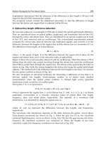
5.3 DSP measurements
The DSP module comes with some debugging functionalities. One of these functionalities
is able to provide the DSP values, from its internal or external memories, via USB to a host
PC. Figure 20 shows the results of a full cross-correlation. For simplicity the CCFs have been
normalized to one. The values show the maximum number of samples (90112) and the peaks,
with each peak describi ng a bit. The value of the bit may be positive (
+1) or negative (−1).
The dif ference between the peaks and the noi se floor is an indicator for the quality of the
communication link.
Time in μs
Voltage in m V
Inphase
Time in μs
Voltage in m V
Quadrature
0 2.5 5 7.5 10 12.5 15 17.5 20 22.5 25
0 2.5 5 7.5 10 12.5 15 17.5 20 22.5
25
-20
-15
-10
-5
0
5
10
15
20
-20
-15
-10
-5
0
5
10
15
20
(a) IQ signal after demodulator / 2 Transponders
Time in μs
Voltage in V
Inphase
Time in μs
Voltage in V
Quadrature
0 2.5 5 7.5 10 12.5 15 17.5 20 22.5 25
0 2.5 5 7.5 10 12.5
15
17.5 20 22.5 25
-0.6
-0.4
-0.2
0
0.2
0.4
0.6
-0.6
-0.4
-0.2
0
0.2
0.4
0.6
(b) IQ signal after baseband processing /
2 Transponders
Fig. 19. IQ signals after de modulator (right) and after baseband processi ng (left)
6. Results
According t o the measurements the proposed system worked as expected. It was proved
that the UHF RFID system for broadcasting information data using a CDMA method worked
out ver y good. During the experiments there was a maximum di stance to the antennas
being around 15 m. The transmitted RF-power at 866.5 MHz was 20 dBm. The introduced
transponders are semi-pas sive, which means that the communication link is still passive,
whereas the data gene ration (on the transponder’s sid e) is active, driven by 3.3 V power
supplies.
Smaller problems arose, when v arious transponder had a different path length to the
antennas. In that case one transpo nder (the neares t) do minated the second transponder (more
far away) which often occurred to a non-detection of transponder two. This problem is known
324
Current Trends and Challenges in RFID
Using CDMA as Anti-Collision Method
for RFID - Research & Applications 21
Sample index
Normalized CCF
CCF of Q component with Code 1 (Transponder 1)
Sample index
Normalized CCF
CCF of I component with Code 2 (Transponder 2)
0 10000 20000 30000 40000
50000
60000 70000 80000 90000
0 10000 20000 30000 40000 50000 60000 70000 80000 90000
-1
-0.5
0
0.5
1
-1
-0.5
0
0.5
1
Fig. 20. Cross-correlation of signals with origin spreading codes - Process of despreading /
2 Transponde rs
in CDMA systems and is referred to as near-far problem (Andrews, 2005). One possibility
to red uce the near-far effect is t he usage of Huffman sequences (Liu & Guo, 2008). But this
approach asks fo r more than 2 states of the load impedance of the transponder’s modulator.
Nevertheless, carried out indoor exp eriments showed that the near-far effect of the propose d
system is, in fact, very low.
Also, theoretical work, which states an advantage (this statement is only valid for certain
cases) of CDMA-base d RFID systems compared to state-of-the-art RFID systems based on
TDMA methods, complies with the measured results of the proposed CDMA-based UHF
RFID system.
7. Conclusion
This article presented an implementation of a CDMA-based RFID sys tem work ing in the
UHF region. At the beginning the article gave a short introduction to anti-collision methods
used in RFID technology. Subsequently, a performance comparison was made to show the
effect of using CDMA in RFID. It could be stated, that CDMA does outperform traditional
TDMA methods, but only in particular fields of applications. The implemented RFID system
itself is build upon a Transmitting system provid ing a continuous electromagne tic wave. This
emitted RF carrier is backscattered through one or more designed UHF tags. Each of these
semi- passive operating transponde rs gener ate a unique sp reading sequence. The proposed
spreading sequences are Gold codes providing a good orthogonality. A simple modulator
on the transponder generates the desired backscatter signal. The Receiving system captures
this signal by down mixing the RF si gnal to baseband . Further analog signal processing and
subsequent A/D conversion gives the DSP the chance to despread, demodulate and decode
the desi red transponder signals.
The significant advantage of such a structure compared to present systems lies in the ability
to avoid particular TDMA-based anti-collision schemes. Certainly, this will lead to less time
needed for inventorizing RFID tags, as this can be achieved within one time slot. However, the
number of tags to be read this way, is somewhat limited (due to the usage of CDMA), whereas
TDMA methods may recognize a huge amount of transponders, indeed, at the expens e of time
to identify. Finally, one can say, that the deployment of CDMA is useful in cases where the
number of transponders has an upper limit or is fixed. For such cases the time for detection
325
Using CDMA as Anti-Collision Method for RFID - Research & Applications
22 Will-be-set-by-IN-TECH
may be minimized using appropriate spreading codes. Fields of application mainly include
closed systems, e.g., found in industrial facilities.
8. Acknowledgment
I would like to thank Fabian Schuh, and in particular Ingo Altmann, without whom this
publication would not have been possible. His ideas, work, and research on this topic made
a big contri bution to this chapter. Also, I would like to thank my colleagues for their very
productive ideas and valuable discussions.
To my wife Sonja, my daug hters Jenny and Jolina, and my son Tom, for having the patience
with me, despite my long periods in the office which decrease the amount of time I can spe nd
with them.
9. References
Abramson, N. (1970). THE ALOHA SYSTE M: another alternative for computer
communications, Proceedings of the November 17-19, 1970, fall joint computer conference,
AFIPS ’70 (Fall), ACM, New York, NY, USA, pp. 281–285.
URL: />Aein, Joseph M. (1964). Multiple Access to a Hard-Limiting Communication-Satellite
Repeater, Space Electronics and Telemetry, IEEE Transactions on 10(4): 159–167.
URL: 10.1109/TS ET.1964.4337583
Analog Devices (2010a). AD9248: Dual 14-Bit, 20/40/65 MSPS, 3 V Analog- to-Digital
Converter.
URL: />products/product.html
Analog Devices (2010b). ADSP-21469: High Performance Fourth Generation DSP.
URL: />/product.html
Andrews, J. (2005). Inter ference cancellation for cellular systems: A contemporary overview,
IEEE Wireless Communications 12(2): 19–29.
Bang, O., Kim, S. & Le e, H. (2009). Identification of RFID tags in dynamic framed slotted
Aloha, Advanced Communication Technology, 2009. ICACT 2009. 11th Int ernational
Conference on, Vol. 01, pp. 354 –357.
Bertsekas, D. & Gallager, R. (1992). Data networks (2nd ed.), Prentice-Hall, Inc., Upper Saddle
River, NJ, USA.
Choi, J. H., Lee, D. & Lee, H. (2007). Query tree-based reservation for efficient RFID tag
anti-collision, Communications Letters, IEEE 11(1): 85 –87.
Cui, Y. & Zhao, Y. (2009). A modified Q-parameter anti-collision scheme for RFID systems,
Ultra Modern Telecommunications Workshops, 2009. ICUMT ’09. International Conference
on, pp. 1 –4.
Dobkin, D. (2008). The RF in RFID: passive UHF RFID in practice,Newnes.
EPCglobal Inc. (2008). Class 1 Generation 2 UHF Air Inter face Protocol Standard "Gen 2" v.
1.2.0.
Finkenzeller, K. (2003). RFID handbook, Wiley West Sussex, England.
Fuschini , F., Piersanti, C., Paolazzi, F. & Falciasecca, G. (2008). On the Efficiency of Load
Modulation in RFID Systems Op erating in Real Environment, Antennas and Wireless
Propagation Letters, IEEE 7: 243 –246.
326
Current Trends and Challenges in RFID
Using CDMA as Anti-Collision Method
for RFID - Research & Applications 23
Gold, R. (1967a). Optimal binary sequence s for spread spectrum multiplex ing (cor resp.),
Information Theory, IEEE Transactions on 13(4): 619 – 621.
Gold, R. (1967b). Optimal binary sequences for spread spectrum multiplexing (Corresp.),
Information Theory, IEEE Transactions on 13(4): 619 – 621.
Gopalan, S., Karystinos , G. & Pados, D. (2005). Capacity, throughput, and delay of
slotted ALOHA DS-CDMA links with adaptive space-time auxiliary-vector receivers,
Wireless Communications, IEEE Transactions on 4(1): 79 – 92.
Hansen, R. (1989). Rel ationships between antennas as scatterers and as radiators, Proceedings
of the IEEE 77(5): 659 –662.
IPICO (2009). IPICO’s IP-X RFID Air-interface Protocol.
URL: />Karthaus, U. & Fischer, M. (2003). Fully integrated passive uhf rfid trans ponder ic with 16, 7μw
minimum rf input power, IEEE 38(10): 1602–1608.
Kleinrock , L. & Tobagi, F. (1975). Packet Switching in Rad io Channels: Part
I–Carrier Sense Multiple-Access Modes and Their Throug hput-Delay Characteristics,
Communications, IEEE Transactions on 23(12): 1400 – 1416.
Lee, D., Bang, O., Im, S. & Lee, H. (2008). Efficient dual bias Q-Algorithm and optimum
weights for EPC Class 1 Generation 2 Protocol, Wireless Conference, 2008. EW 2008.
14th European, pp. 1 –5.
Linear Technology (2010a) . LT5575 - 800MHz to 2.7GHz High Linearity Direct Conversion
Quadrature Demodulator.
URL: near.com/pc/productDetail.jsp?navI d=H0,C1,C1011,C1725,P36240
Linear Technol ogy (2010b). LT 6604-2.5 - Dual Very Lo w Noise, Differenti al Ampli?er and
2.5MHz Lowpass Filter.
URL: sp?navId=H0,C1,C1154,C1008,C1148,
P85251
Linear Technology (2010c). LT C6420-20 - Dual Matche d 1.8GHz Differential Amplifier s/ADC
Drivers.
URL: sp?navId=H0,C1,C1154,C1009,C1126,
P80614
Linear Technology (2010d). LTC6421-20 - Dual Matched 1.3GHz Differential Amplifiers/ADC
Drivers.
URL: d=H0,C1,C1154,C1009,C1126,P80589
Linnartz, J P. M. & Vvedenskaya, N. D. (2009). DS-CDMA Packet Network with Random
Access.
URL: />Liu, D., Wang, Z. , Tan, J., Min, H. & Wang, J. (2009). A LOHA algorithm considering the
slot duration difference in RFID system, RFID, 2009 IEEE International Conference on,
pp. 56 –63.
Liu, H. & Guo, X. (2008). A passive UHF RFID system with Huf fman sequence spreading
backscatter signals, Proceedings of the 1st international conference on The internet of
things, Sprin ger-Verlag, pp. 184–195.
Liu, Q., Yang, E H. & Zhang, Z. (2001). Throughp ut analysis of CDMA systems using
multiuser receivers, Communications, IEEE Transactions on 49(7): 1192 –1202.
Liu, Z. & El Zarki, M. (1994). Performance analysis of DS-CDMA with slo tted ALOHA
random access for packet PCNs, Personal, Indoor and Mobile Radio Communications,
1994. Wireless Networks - Catching the Mobile Future., 5th IEEE International Symposium
on, Vol. 4, pp. 1034 –1039 vol.4.
327
Using CDMA as Anti-Collision Method for RFID - Research & Applications
24 Will-be-set-by-IN-TECH
Lo, F. L., Ng, T. S. & Yuk, T. (1996). Performance analysis of a fully-connecte d, full-dupl ex
CDMA ALOHA network with channel sensing and collision detection, Selected Areas
in Communications, IEEE Journal on 14(9): 1708 –1716.
Loeffler, A., Schuh, F. & Gerhaeuser, H. (2010). Realization of a CDMA-based RFID System
Using a Semi-active UHF Transponder, Wireless and Mobile Communications (ICWMC),
2010 6th International Conference on, pp. 5 –10.
Maguire, Y. & Pappu, R. (2009). An Optimal Q-Algo rithm for the ISO 18000-6C RFID Protocol,
Automation Science and Engineering, IEEE Transactions on 6(1): 16 –24.
Makwimanloy, S., Kovintavewat, P., Ketprom, U. & Tantibundhit, C. (2009). A novel
anti-collision algorithm for high-density RFID tags, Electrical Engineering/Electronics,
Computer, Telecommunications and Information Technology, 2009. ECTI-CON 2009. 6th
International Conference on, Vol. 02, pp. 848 –851.
Mutti, C. & Floerkemeier, C. (2008). CDMA-based RFID Systems in Dense Scenarios: Concepts
and Challenges, RFID, 2008 IEEE International Conference on, pp. 215–222.
Nikitin, P. & Rao, K. (2008). Antennas and propagation in uhf rfid sy stems, RFID, 2008 IEEE
International Conference on, pp. 277 –288.
Pardo, D., Vaz, A., Gil, S., G omez, J., Ubarretx ena, A., Puente, D., Morales-Ramos, R.,
Garcia-Alonso, A. & Berenguer, R. (2007). Desig n criteria for full passive long
range uhf rfid sensor for human body tem perature moni toring, RFID, 2007. IEEE
International Conference on, pp. 141–148.
Penttila, K., Keski lammi, M., Sydanheimo, L. & Kivikosk i, M. (2006). Radar cross-section
analysis for passive RFID systems, Microwaves, Antennas and Propagation, IEE
Proceedings - 153(1): 103 – 109.
Pupunwiwat, P. & Stantic, B. (2010). A RFID Explicit Tag Estimation Scheme for Dynamic
Framed-Slot ALOHA Anti-Collision, Wireless Commun ications Networking and Mobile
Computing (WiCOM), 2010 6th International Conference on, pp. 1 –4.
Rembold, B. (2009). Optimum mod ulation efficiency and sideband backscatter power
response of RFID-tags, Frequenz - Journal of RF-Engineering and Telecommunications
63(1 -2): 9 –13.
Roberts, L. G. (1975). ALOHA packet system with and without slots and capture, SIGCOMM
Comput. Commun. Rev. 5: 28–42.
URL: />Sakata, A., Yamazato, T., Okada, H. & KATAYAMAt, M. (2007). T hroughput
Compari son of CSMA and CDM A slotted ALOHA in Inter- Vehicle Communication,
Telecommunications, 2007. ITST ’07. 7th International Conference on ITS, pp. 1 –6.
Sastry, A. (1984). Effect of Acknowledgment Traffic on the Performance of Slotted
ALOHA-Code Division Multiple Access Systems, Communications, IEEE Transactions
on 32(11): 1219 – 1222.
van Nee, R., van Wolfswinkel, R. & Prasad, R. (1995). Slotted ALOHA and code division
multiple access techniques for land-mobile satellite personal communications,
Selected Areas in Communications, IEEE Journal on 13(2): 382 –388.
Wang, L C. & Liu, H C. (2006). A Novel Anti-Collision Algorithm for EPC Gen2
RFID Systems, Wireless Communication Systems, 2006. ISWCS ’06. 3rd International
Symposium on, pp. 761 –765.
Zhang, Z., Lu, Z., Pang, Z., Yan, X., Chen, Q. & Zheng, L R. (2010). A Low
Delay M ultiple Reader Passive RFID System Using Orthogonal TH-PPM IR-UWB,
Computer Communications and Networks (ICCCN), 2010 Proceedings of 19th International
Conference on, pp. 1 –6.
328
Current Trends and Challenges in RFID
16
An Unconditionally Secure Lightweight
RFID Authentication Protocol
with Untraceability
Hung-Yu Chien
1
, Jia-Zhen Yen
2
and Tzong-Chen Wu
2,3
1
Department of Information Management,
National Chi-Nan University
2
Department of Information Management,
National Taiwan University of Science and Technology
3
Taiwan Information Security Center (TWISC) at
National Taiwan University of Science and Technology
Taiwan
1. Introduction
Radio frequency identification (RFID) is a wireless technology that uses radio signals to
identify objects automatically and remotely. The most popular tags are passive devices
owing to their low cost. Nowadays, RFID devices are widely deployed in many
applications, such as supply chain management, inventory control, contactless credit card
and so on, due to the low-cost and convenience in identifying objects with non-line-of sight
reading, However, there are many potential security threats around the tiny RFID tags
attached to users. The carrying items or privacy information contained in these tags might
be compromised. Furthermore, low-cost makes these tags very resource-limited, which
makes it very challenging to design secure protocols for these tags.
From the point of end user’s side, a secure RFID system should provide the capability of
location/content privacy protection, anonymity, untraceability and availability [2]. Several
RFID lightweight authentication protocols like [4-10] have been developed, but not all of
them satisfy all the security requirements. All the previously proposed protocols are
designed to be computationally secure, i.e., the security depends on the hardness of solving
mathematical problem. Recently, Alomair et al. [1] proposed an unconditionally secure
lightweight RFID (UCS-RFID for short) protocol, and claimed that their protocol achieved
unconditional secrecy and unconditionally integrity. The security of the UCS-RFID protocol
depends on the freshness of the keys. However, the UCS-RFID protocol does not achieve
backward untraceability, even though it does achieve forward untractability.
Forward and backward untraceability are important privacy properties for RFID
authentication protocol [4]. Forward untraceability requires that even if the adversary
reveals the internal state of a tag at time τ, the adversary still cannot know whether a
transaction after time τ + δ (for some δ > 0) involves the same tag or not, provided that the
adversary does not eavesdrop on the tag continuously after time τ. Backward untraceability
Current Trends and Challenges in RFID
330
requires that even if the adversary reveals the internal state of a tag at time τ, the adversary
is not able to tell whether a transaction before time τ involves the same tag or not [3]. These
two properties are important for the RFID systems that the equipped tags are low-cost and
potentially prone to being captured and compromised.
Notation Description
R
RFID reader
i
T
i-th RFID tag
S
Back-end database
p
A 2N-bit prime integer, where N is …
p
Z
The finite integer ring with usual addition and multiplication modulo
p
*
p
Z
The multiplicative group modulo
p,
*
p
Z
contains all non-zero elements of
p
Z
; that
is,
*
\{0}
pp
ZZ
()m
n
n denotes a 2N-bit random number which is drawn uniformly from the
*
p
Z , m
denotes that it is used in the m-th session
()m
l
n
The left
N most significant bits of
()m
n
()m
r
n
The right
N least significant bits of
()m
n
()m
i
K
The secret keys of the RFID tag
i
T
. The
y
consist of five subke
y
s, i.e.,
() () () () () ()
( , , , , )
m mmmmm
iaibicidiei
K kkkkk . The superscript m denotes the m-th run, and the
subscript i denote the i–th tag
i
T .
(0)
ai
k
A subkey which is initially drawn independently and uniformly from
2
N
Z
(0)
bi
k
A subkey which is initially drawn uniformly from
p
Z
(0)
ci
k
A subkey which is initially drawn independently and uniformly from
*
p
Z
(0)
di
k
A subkey which is initially drawn independently and uniformly from
2
N
Z
(0)
ei
k
A subkey which is initially drawn independently and uniformly from
*
p
Z that
will be used for updating the secret keys to maintain certain properties
Table 1. Notations or Symbols
An Unconditionally Secure Lightweight RFID Authentication Protocol with Untraceability
331
In this book chapter, we first examine the USC-RFID protocol, and show that the USC-RFID
protocol does not achieve backward untraceability. After that, we will extend the USC-RFID
protocol to an enforced one with untraceability.
2. The UCS-RFID protocol
The UCS-RFID procotol [1] is a lightweight RFID authentication protocol and is the first
RFID protocol providing unconditional security for low-cost tags. The UCS-RFID protocol
has the merits that it does not require tags to support random number generation and it
requires only one simple multiplication on tags. The security of this protocol mainly relies
on the RFID reader’s capability to deliver random numbers to RFID tags in an authenticated
and secure way.
The UCS-RFID protocol consists of four phases: the tag identification phase, the reader
authentication phase, the tag authentication phase, and the key updating phase (see Fig. 1
for more details). For the convenience of describing the UCS-RFID protocol, we first
introduce the notations or symbols shown in Table 1. Initially, each tag
T
i
has a secret key
set
(0)
i
K shared with the back-end database. In the following, we describe the m-th run of the
protocol.
T
ag identification phase
i. The reader R sends a Hello message to the tag T
i
.
ii.
T
i
sends its message A
(m)
to R, and R forwards this message
()m
i
A to the back-end
database
S.
iii.
S looks up the database for the secret key
()m
i
K corresponding to the message
()m
i
A . If the
()m
i
A could be identified as a valid identifier, then S sends back the tag’s secret key
()m
i
K to
R. Otherwise, the tag T
i
is rejected.
Reader Authentication Phase
i. R generates a random number
()m
n , computes
() () ()
mod
mmm
i
b
Bnk
p
and
() () ()
mod
mmm
i
c
Cnk
p
, and then sends these two messages (B
(m)
, C
(m)
) to T
i
.
ii.
After receiving B
(m)
and C
(m)
, T
i
extracts
() () ()
() mod
mmm
i
b
nBk
p
, and then verifies its
integrity via checking whether the equation
() () () ()
() mod
mm m m
ii
bc
Bk k C
p
holds. If so,
R is authenticated; otherwise, the tag aborts the protocol.
Tag Authentication Phase
i. T
i
computes
() () ()
mm m
i
ld
Dn k and returns this value.
ii.
After receiving the value, R verifies whether the equation
?
() () ()
mm m
i
ld
Dn k
holds. If so, the tag is authenticated; Otherwise, the tag is rejected.
Key Updating Phase: After a successful mutual authentication between
the tag and the
reader, the secret key and the tag identifier are updated at the back-end database and the tag
respectively as specified in Fig. 1. Fig. 1 depicts the protocol for the
m-th run.
The above protocol cannot deter possible denial-of-service attacks (DOS attacks), and Alomair
et al. had extended the above protocol to prevent DOS attacks and possible key exposure
Current Trends and Challenges in RFID
332
problem. Since these extensions are not relevant to our improvements, we will not discuss
these parts for easy presentation, and interested readers are referred to [1] for details.
Fig. 1. The UCS-RFID protocol.
3. Extending the USC-RFID to untraceability
In Section 3.1, we examine the untraceability of the USC-RFID protocol, and then provide an
improved scheme to enhance its untraceability.
An Unconditionally Secure Lightweight RFID Authentication Protocol with Untraceability
333
3.1 Untraceability of the UCS-RFID protocol
Here we show that the UCS-RFID protocol does not provide backward untraceability as
follows.
Suppose the tag
T
i
has been compromised and the internal secrets
() ( 1) ()
mod 2
mm m
N
lai
An k
and
()m
i
K =(
()m
ai
k ,
()m
bi
k ,
()m
ci
k ,
()m
di
k ,
()m
ei
k ) are revealed at time τ. Let
(
A, B, C, D) be one eavesdropped message. Then we can tell whether the message (A, B, C,
D) comes from the same tag or not as follows.
1.
Derive
(1) () ()
mod 2
mmm
N
lai
nAk
.
2.
Derive
(1) (1)mm
i
dl
kDn
,
(1) () (1)mmm
rdidi
nkk
and
(1) (1) (1)
||
mm m
lr
nn n
.
3.
Now we can derive the previous internal state
(1)
1
m
(m ) (m)
ai ai
r
knk
,
(1)
1-1
() mod
m
(m ) (m)
ei ei
kkn
p
,
(1)
11
(mod)
m
(m ) (m) (m )
bi bi ei
kkk pn
,
(1)
111
(()mod)
m
(m ) (m) (m )
ci ci ei
kkk pn
and
(1)
1
m
(m ) (m)
di r di
knk
.
4.
Now we check whether the two equations
?
(1) (1)
mod
mm
i
b
Bn k p
and
?
(1) (1)
mod
mm
i
c
Cn k p
hold. It is obvious that if the two equations hold, then the
message (
A, B, C, D) is the
(1) (1) (1) (1)
(,,,)
mm m m
ABCD
from the compromised tag.
We can recursively apply the above steps to trace the messages from the same tag for
i-
th run, where 1
im
. That is, the USC-RFID protocol cannot provide backward
untraceability.
Even though the USC-RFID protocol does not satisfy backward untraceability, it does
provide forward untraceability. This is because, in forward untraceability, if the adversary
reveals the internal state of a tag at time
τ, it is required that the adversary does not
eavesdrop on the tag
continuously after time τ. It is this break of eavesdropping that makes
the USC-RFID satisfy forward untraceability.
3.2 Enhancing the untraceability
The key to find the link in our backward traceability is that the equation
() ( 1) ()
mod 2
mm m
N
lai
An k
contains only one unknown value
(1)m
l
n
when the adversary learn
the internal state
()m
A and
()m
i
K =(
()m
ai
k ,
()m
bi
k ,
()m
ci
k ,
()m
di
k ,
()m
ei
k ); therefore, the adversary can
derive
(1) () ()
mod 2
mmm
N
lai
nAk
and the other values accordingly. We also notice that each
of the other key updating equations in the key updating phase contains at least two
unknown values. Therefore, we can amend the protocol by simply modifying this equation
() ( 1) ()
mod 2
mm m
N
lai
An k
to contain two unknowns. One simple suggestion is
that
() ( 1) ( 1)
mod 2
mm m
N
lai
An k
. With this modification, the adversary should solve two
unknowns in each equation to derive the secret even assume he has learned the current state
(
()m
A ,
()m
ai
k ,
()m
bi
k ,
()m
ci
k ,
()m
di
k ,
()m
ei
k ). It, therefore, cannot provide adversaries a unique and
deterministic link to trace the tag.
4. Conclusion
In this book chapter, we have shown that the UCS-RFID protocol which is the first
unconditionally secure mutual authentication protocol for RFID systems cannot satisfy
backward untraceability, and we have proposed a simple amendment to enhance its
Current Trends and Challenges in RFID
334
backward untraceability. The unconditional secure RFID protocol is very promising
approach for RFID security. In this book chapter, we have enhanced the first unconditional
secure RFID protocol to satisfy untraceability. Our future work is to further analyze and
improve the security of unconditional secure RFID protocols.
5. References
[1] B. Alomair, A. Clark, J. Cuellar, and R. Poovendran, Securing Low-Cost RFID Systems:
an Unconditionally Secure Approach, 2010 Workshop on RFID Security –
RFIDsec'10 Asia, 2010.
[2] H. -Y. Chien and C. -S. Laih, ECC-Based Lightweight Authentication Protocol with
Untraceability for Low-Cost RFID, Journal of Parallel and Distributed Computing.
69 (10) (2009) 848-853.
[3] R. C. -W. Phan, J. Wu and K. Ouafi, Privacy Analysis of Forward and Backward
Untraceable RFID Authentication Schemes, 2008. Available from :
<
[4] A. D. Henrici, and P. MÄuller, “Hash-based Enhancement of Location Privacy for Radio-
Frequency Identification Devices using Varying Identifiers,” In the Proceedings of
PerSec'04 at IEEE PerCom, 2004, pp.149-153.
[5] S. Karthikeyan, M. Nesterenko, “RFID security without extensive cryptography,”
Proceedings of the 3rd ACM workshop on Security of ad hoc and sensor networks,
2005, pp. 63-67.
[6] D. Molnar and D. Wagner, “Privacy and security in library RFID: Issues, practices, and
architectures,” Conference on Computer and Communications Security – CCS’04,
2004, pp. 210–219.
[7] M. Ohkubo, K. Suzki and S. Kinoshita, ”Cryptographic Approach to ‘Privacy-Friendly’
Tags,” In RFID Privacy Workshop, 2003.
[8] S. A. Weis, “Security and Privacy in Radio-Frequency Identification Devices,” Masters
Thesis MIT, 2003.
[9] G. Avoine, E. Dysli, and P. Oechslin, “Reducing time complexity in RFID systems,” The
12th Annual Workshop on Selected Areas in Cryptography(SAC), 2005.
[10] H. Y. Chien, “SASI: A New Ultra-Lightweight RFID Authentication Protocol Providing
Strong Authentication and Strong Integrity”, IEEE Transactions on Dependable and
Secure Computing 4(4), pp. 337-340, October, 2007.
17
Application of Monte Carlo Method for
Determining the Interrogation Zone in
Anticollision Radio Frequency
Identification Systems
Piotr Jankowski-Mihułowicz and Włodzimierz Kalita
Department of Electronic and Communications Systems,
Rzeszów University of Technology
Poland
1. Introduction
Current problems that occur in the field of anticollision Radio Frequency IDentification
(RFID) prototype systems are solved in experimental way (De Blasi et al., 2010; Lehto et al.,
2009; Polivka et al., 2009; Brown, 2007; Clarke et al., 2006; Penttilä et al., 2006; Jones &
Chung, 2007). The low efficiency coefficient of identification for the multiple objects
localized in the space Ω
ID
doesn't allow to realize practical projects, such as, the
identification of Fast Moving Consumer Goods (FMCG) – Fig. 1. In the light of nascent and
modified legal communications standards, like for example, Electronic Product Code (EPC)
in the area of UHF and HF ISO 18000-6, ISO 15693, ISO 18000-3 normalizations, there is a
necessity to continue complex theoretical research and experimental investigations in the
range of simultaneous analysis of EM field, communication protocols, and electric aspects of
operating conditions of efficiency identification in anticollision RFID systems.
Fig. 1. Illustration of RFID automatic identification process
Current Trends and Challenges in RFID
336
To generalise, the operation of passive anticollision inductive- (LF, HF), and also
propagation (UHF) coupling RFID system is characterized by the interrogation zone (IZ)
which is estimated in any direction of 3D space for a group of electronic tags. The elements
of algorithm of identification of interrogation zone for anticollision RFID system with the
consideration of the energetic (i.e. field and electrical) and communication aspects of
operation conditions have been presented in the following chapter. For calculations of the
interrogation zone the algorithm based on Monte Carlo (MC) method and a computer
program with the use of Mathcad 14 (called JankoRFIDmc’IZ) has been utilized.
2. Determining the interrogation zone using MC method
Unequivocal estimation of the interrogation zone for anticollision RFID system depends on
automatic identification process. In accordance with the conditions of the correct operation
of any RFID system, different locations of many tags strongly change the functioning of an
antenna unit array: read/write device (RWD) and individual tags. The problem of
determining the interrogation zone is related to two cases. In the first of them, an
assumption is made that the location of the n-tags group is determined, whereas in the
second case, all possible locations of the group of n-tags in a space around the RWD antenna
are going to be analyzed. The problem connected with the first case is realizable by the
assumption that the process of determining the interrogation zone in RFID system will be
carried out in a few feedback cycles which allow to find the proper location of tags. The
statement “few feedback cycles” is related to the time which is accepted for determining the
interrogation zone for all n-tags. The mentioned feedback cycles in the carried out
simulation include a modification of the tags location which don't fulfil conditions of the
correct RFID system operation. The problem from the second case is almost impossible to
solve because the prolonged process of calculations would be ineffective. Seemingly, in that
case, a method of "trial and error" during the search of the interrogation zone of RFID
system might be easier to apply, however, the presented MC method is a well-founded
alternative.
The presented premises lean towards the necessity of application of the techniques which
make use of random numbers (Kalos & Whitlock, 2008). The result of this is the solution of
the problem of the n-tags group location, and testing the functional efficiency of the antenna
unit array: read/write device-tags, that is an estimation of anticollision RFID system
interrogation zone for given efficiency of identification
ID
. The percentage of identification
efficiency is given by the equation:
100%
IDOK
ID
l
n
(1)
where l
IDOK
is the number of tags for which the desired read/write operations have been
properly done.
The problem contained in the MC method has a probabilistic nature, and it's solution is
obtained by simulation of the given object (Rubinstein & Kroese, 2007). The simulation
object is represented by the antenna unit array: RWD-tags with the consideration of a
synthesis of this antenna unit array and according to all equations which are going to be
determined during the synthesis of its electric model in an anticollision RFID system.
For a laboratory process of automatic objects identification the solution of the problem
consists in finding the interrogation zone of given RFID system, with its shape, location and
Application of Monte Carlo Method for Determining
the Interrogation Zone in Anticollision Radio Frequency Identification Systems
337
step 1
step 2
step 3
k-step
n-tags located in P
i
(x
i
,y
i
,z
ID
) points,
where i=1 n
x
y
x
Ak
x
Bk
y
Ak
y
Bk
Calculated
interrogation zone
for n-tags which are
located on height z
ID
step k
y
y
B1
y
A1
x
A1
x
B1
x
y
A2
y
A3
x
A2
x
A3
y
B2
y
B3
x
B2
x
B3
y
Bk
x
Bk
x
Ak
y
Ak
x
y
z
Surface where RWD
antenna is located
Surface where n-tags
are located on one height z
ID
Axis of symmetry of RWD antenna
and interrogation zone
of RFID system
z
ID
Ω
ID
z
IDj
Fig. 2. Graphic representation of the process of determining the interrogation zone in
anticollision RFID system using MC method
Current Trends and Challenges in RFID
338
orientation in 3D space assumed. In the conducted research it was assumed that the
demanded area should be square shaped and situated at the z
ID
height, whereas it's location
should be axially - symmetrical and parallel to RWD antenna (Fig. 2). Such an assumption
results from the orientation of tags that are parallel to symmetrical RWD antenna which has,
for example, circular or square shape in inductive coupling RFID systems.
A random layout of n-tags at P
i
points of Cartesian space at (x
i
,y
i
,z
ID
) has been assumed in -
considered in a sequence - k steps during the search of the RFID system interrogation zone.
The random variables x
i
and y
i
, for i=1 n obtain various values which can’t be predicted, but
for which the definite distribution is assumed. The electromagnetic field in any point of
communication space is heterogeneous. This effect becomes the clearer, the nearer to the
surface of RWD antenna, and the farther from its centre a point is situated. This knowledge
allows to make a uniform (rectangular) distribution in intervals: x
Ak
,x
Bk
for the random
variable x
i
, and y
Ak
,y
Bk
for the random variable y
i
, in k-step for the analyzed area. For
uniform distribution of the random variables x
i
and y
i
, and for the definite values of x and y,
the distribution functions are given by: (x-x
Ak
)/(x
Bk
-x
Ak
) and (y-y
Ak
)/(y
Bk
-y
Ak
). It should be
noticed that the random variables x
i
and y
i
are mutually independent. This means that the
random variables x
i
and y
i
are stochastically independent, since the distribution of the x
i
does not depend on the value y
i
and vice versa. In this case, the probability density of a pair
of random variables (x
i
,y
i
) is equal to the product of the probability density (x
i
) and (y
i
)
independently.
In order to determine that the RFID system is functioning correctly for given tags locations it
is not enough to achieve the efficiency of identification
ID
=100% for n-tags and fulfill all
conditions for a correct operation of anticollision RFID system. It cannot be predicted
whether for k area in which all the conditions mentioned above are fulfilled, the coordinates
sampling of tags locations on the surface of their arrangement, allows to fulfill the border
case of a correct operation of the whole RFID system. In k-step for the analyzed area in
which all the conditions of a correct operation of anticollision RFID system for given
efficiency of identification are fulfilled, the practical use of the law of large numbers (Kalos
& Whitlock, 2008) is the solution to this problem. For the random variables x
i
and y
i
independently, the strong law of large numbers for the analyzed case is given by:
1
lim lim 1
2
nm
iAkBk
mi
i
mm
xxx
PP S x p
nm
(2)
1
lim lim 1
2
nm
iAkBk
mi
i
mm
yyy
PP S y p
nm
(3)
where p denotes the expected value of the random variables x
i
and y
i
(which are equal to
zero because the interrogation zone is axially - symmetrical and parallel to RWD antenna),
and PP denotes the probability of sampling of variables for m approaching to infinity, but m
denotes the number of multiple sampling of tags location (i.e. random variables x
i
and y
i
) for
k analyzed area.
What follows from the equations (2) and (3) is that the sequences of random variables S
m
(x
i
)
and S
m
(y
i
) converge with probability “1” to the expected value p=0 of the random variables
x
i
and y
i
. It can be found that the m-tuple increase of the number of the random variables x
i
and y
i
sampling in k-step for the analyzed area lengthens the calculation process during the
simulation of an antenna unit array. In accordance with the law of large numbers, the
Application of Monte Carlo Method for Determining
the Interrogation Zone in Anticollision Radio Frequency Identification Systems
339
probability of a correct estimation of the interrogation zone for RFID system increases. First
of all, this is connected with the examination of a larger number of localized n-tags cases. If
the conditions of the correct operation of anticollision RFID system are not fulfilled in any of
m multiple sampling of tags location for k analyzed area, then the next process of multiple
sampling should be stopped, and it becomes necessary to examine the next (k+1) - smaller
area of tags location in the x-y plane. The MC solution for the analyzed object completes a
procedure which confirms the fulfillment of all conditions for the correct operation of
anticollision RFID system. The procedure is correct for the given efficiency of identification,
and for the area in which all the m multiple sampling of tags location lead to a positive
calculation result of the antenna unit array: read/write device-tags.
Correct selection of the m number, which will be satisfactory under the experiment, as well
as adequate to calculation time and probability of possible tags locations, is a problem. From
equations (2) i (3) which describe the strong law of large numbers, the dependence of
probability PP for the random variables x
i
and y
i
(which are stochastically independent, and
which have a uniform distribution) in function of the m·n has been presented in Fig. 3.
Fig. 3. Example result of probability PP of sampling of independent random variables x
i
and
y
i
in function of numbers product: multiple sampling of m and n-tags location
Assuming that the probability PP exceeds the value 0.95 independently for the random
variables x
i
and y
i
, the value m·n=250 was determined during the calculation of interrogation
zone in automatic identification process. These parameters were determined for 10
6
sampling of 250 independent random variables x
i
and y
i
which have a uniform distribution.
For every sampling, the minimum value of probability PP has been searched. The
determined value of m·n=250 is compatible with a central limit theorem which states that
the sum of a sufficiently large number of identically distributed independent random
variables, each with finite mean and variance, is going to be approximately normally
distributed (Rice, 2006). Uniform distribution of the random variables x
i
and y
i
is in fact
different from a normal distribution, but - for this determined value of m·n=250 - random
variables x
i
and y
i
are convergent to a normal distribution. In this case, the obtained
compatibility with a central limit theorem confirms the correctness of product m·n=250.
Current Trends and Challenges in RFID
340
The presented idea of n-tags analysis at a specifically determined z
ID
height, results from a
practical demand for realization of automatic identification process with the anticollision
RFID systems. The identification of single products which are located inside a container on a
pallet can be the practical example of this process. Identification of single objects separately
is impossible in this situation, but their location on a pallet is mostly scheduled - because
logistic system has to work satisfactorily (Mo & Lorchirachoonkul, 2010; Shaoping Lu et al.,
2007; March, 2005; Jones & Chung, 2007). The development of the presented MC solution on
an area Ω
ID
in the x-y-z space requires investigation of every j-surface independently where
tags will be located on the whole area Ω
ID
at points P
ij
(x
i
,y
i
,z
IDj
) - (Fig. 2). If all n-tags are in a
disordered state in the space Ω
ID
, then the stochastic independence of all the coordinates x
i
,
y
i
, z
i
should be assumed. However, this idea is very complicated because it is not enough to
assume that all the pairs of random variables are independent. Taking into consideration the
practical requirements of different automatic identification processes, the example presented
above is marginal, yet very interesting from a scientific point of view.
3. Conditions of correct operation of anticollision RFID system with inductive
coupling
Passive RFID systems with inductive coupling are widespread (ID World, 2009; Wolfram
et al., 2008; Jones & Chung, 2007; Paret, 2005). These systems can operate in individual and
anticollision regime (Finkenzeller, 2003), and the need to design such systems appears more
often nowadays. Functioning of RFID systems with inductive coupling is based on the use
of energy which is stored in a magnetic field (Chen & Thomas, 2001; Rautio, 2003; Troyke &
Edgington, 2000). The kind of executed operation in individual phases of the exchange of
data between units of a system is essential during communication in anticollision
identification process (Jankowski-Mihułowicz et al., 2008). The basic condition of effective
operation of the system is the proper supply of each tag in a heterogeneous magnetic field
created by RWD antenna loop. A minimal value of energy (necessary for proper read/write
operation of the tag) is determined by minimal value of magnetic induction B
min
in each
point P(x,y,z) of its location (Fig. 4).
Analysis of the general RFID system schema allows for the determination of the complete
impedance of RWD antenna Z
R
, taking into account an influence of all coupled tags.
Maximal change of the impedance Z
R
under the influence of the tags is expressed by the
maximum value of difference in impedance arguments Δφ
Rmax
without the tags and with
them, respectively. The value Δφ
Rmax
is limited to assure the correct operation of the system.
A determination of communication conditions for proper operation of RWD-tags antenna
set is also possible on the basis of the schema analysis, taking into consideration the
properties of data transmission process (transmitted frequency band, data flowability and
required time relations in selected communication protocol).
The quality factor Q is a measure of tag antenna unit functioning efficiency in areas of
energy transfer and communication conditions in RFID systems with inductive coupling
(Newman et al., 1975; Redinger et al., 2003). These conditions are expressed by maximal
values of quality factors of RWD and tag antennas: Q
Rmax
and Q
Tmax
, respectively. In this
case, it is necessary to observe that selection of value Q
Tmax
is compromised by energy
(utilization of magnetic field energy) and communication requirements (Jankowski-
Mihułowicz & Kalita, 2009).
Application of Monte Carlo Method for Determining
the Interrogation Zone in Anticollision Radio Frequency Identification Systems
341
Fig. 4. Block diagram of anticollision RFID system with inductive coupling
During the synthesis of tag antenna, the changes of this parameter can be made by
inductance change (indirectly – by changing the effective resistance of antenna loop),
adjusted to requirements of the shape and geometrical sizes of an electronic tag. The proper
synthesis of interrogation zone of RFID system is closely connected with three aspects which
concern the maximum value of Q factor for the operating tag. The first of these aspects is
related to the correct operating of the tag supply system, that is, the possibility of radio
communication appearing. The second aspect concerns the necessity to obtain the required
data transmission bit-rate (and also the bandwidth) in direction: tag-read/write device. The
third aspect concerns the impulse and step response of tag circuit in case of reverse data
transmission, to provide a correct identification of commands sent from the RWD. The last
two aspects should result directly or indirectly from the electronic tag chip specification for
which the antenna is going to be projected. The first aspect should be considered at the stage
of antenna synthesis, and the value of Q factor should contain all of the mentioned
limitations of operating passive tag. It is essential to ensure the homogeneous proper
interrogation zone of RFID system that is a mutual overlay of zones that result from
conditions of tag supply (by absorbing the energy of magnetic field) and the radio
communication carried in the system (realized with the suitable value of signal-to-noise).
Paying attention to the maximum work distance between elements of the RFID system, in
particular for systems working in the RFID far field, it is necessary to estimate the simulated
Current Trends and Challenges in RFID
342
and built antenna set RWD-tags in relation to the obligatory normalizations of
communication and EMC (ETSI EN 300 330, 2010; Jankowski-Mihułowicz, 2010).
4. Energy transfer in passive anticollision RFID system with inductive
coupling – fundamental equations
4.1 EM field aspects
Analysis of the read/write device antenna unit allows to make an assumption that the
antenna loop current (I
R
) is constant along the whole flow way (Fig. 5).
Fig. 5. Analyzed cases of RWD antenna loop: a) circular loop, b) loop of polygon shape,
c) some realizations of tested RWD antennas
Change of the electric charge density in time equals zero, so in that case the electric current
density divergence equals zero as well. Making these assumptions permits to apply the
magnetostatic laws to magnetic field analysis for any RWD shape. In accordance with vector
Biot-Savart law, the magnetic induction value of
B in any space point P(x,y,z) is given by the
equation:
0
3
d
4
RR
IN
b1
b1
lr
B
r
(4)
where:
0
=410
-7
H/m.
Application of Monte Carlo Method for Determining
the Interrogation Zone in Anticollision Radio Frequency Identification Systems
343
Application of the Biot-Savart law for the RWD’s antenna loops is possible by the additional
assumptions that the wire diameter of RWD’s antenna is negligible in relation to the
geometrical loop sizes, and also that there is full inductive coupling between the individual
loop turns (N
R
).
For the circle-shaped loop (Fig. 5-a), the axial symmetry permits convenient change from
Cartesian to cylindrical coordinates. The vector describing the d
l location at P point, in
which the value of magnetic induction is calculated, is given by the formula:
b1 b 1
rrr (5)
where the vector describing d
l element location that changes in
angle function, and the
vector describing location of point P, are given as follows:
cos( )
sin( )
0
R
R
r
r
1
r
(6)
x
y
z
b
r
(7)
The unit vector connected with
dd
R
r
l is given by the formula:
sin( )
cos( )
0
u
(8)
Changing the coordinate system leads to final equation, which describes the magnetic vector
at any space location with (x,y,z) coordinates for circle-shaped RWD loop:
2
0
3
0
d
4
R
RR
r
IN
b1
b1
ur
B
r
(9)
In the case of RWD antenna loop, constructed as polygon (Fig. 5-b, c), Biot-Savart law with
principle of superposition permits to add at location P vectors, that descend from individual
antenna parts. In this case, the total magnetic induction is calculated from the equation:
i
i
BB
(10)
where i denotes analysed side for RWD antenna loop, constructed as polygon.
The obtained vector equations permit numerical calculating of the value of magnetic
induction separately for individual components in directions x, y and z (B
x
, B
y
, B
z
). The
components of magnetic induction B in any space point P(x,y,z) are given for a circular loop
shape (Fig. 5-a) by the following equations:
2
0
3/2
0
2
2
2
cos( )
d
4
cos( ) sin( )
RR
R
x
RR
IN
zr
B
xr yr z
(11)