Electromagnetic Waves Propagation in Complex Matter Part 6 ppt
Bạn đang xem bản rút gọn của tài liệu. Xem và tải ngay bản đầy đủ của tài liệu tại đây (1.89 MB, 20 trang )
Nonlinear Propagation of Electromagnetic Waves in Antiferromagnet
87
2
[(1 ) 1]exp( )
cos ( ) ( )sin [1 (1 )]sin
y
yyy
ik d
f
kd + +i kd i + kd
(5-7)
where d is the film thickness,
0
=
yy
kk
and
0
=
yy
kk
. The wave amplitudes
0
R
and
0
T of R and T are not necessary for seeking the SHG, so they are given up here.To solve
the output amplitudes of SHG,
s
R and
s
T , we should look for the solution of the SH wave
equation in the film. In fact, there are three component equations, but only one contains a
source term and this equation is
22
(2)
22
22
( ) () (/) () (/) ()
sz s s sz s s z s
HcHcm
xy
(5-8)
The other two are homogeneous and do not contain the field component
()
sz s
H
. In
addition, the other SH components cannot emerge voluntarily without source terms, so it is
evident that the SH wave is a TM wave. Because the SH magnetization and pump field in
the film both have been given, to find the solution of equation (5-8) is easy. Let
( ) [ exp( ) exp( ) exp(2 )
exp( 2 ) ]exp(2 )
sz s s sy s sy y
yxs
HAik
y
Bik
y
aik
y
bikycikxit
(5-9)
with
221/2
[( /) 4 ]
sy s x
kck
. Substituting SH solution (5-9), expression (5-1) and solution
(5-6a) into equation (5-8), we find the nonlinear amplitudes
(2)
2
22222
0
0
2
0
()
[(1 ) (1 )]
(1)(/)
zxx s
yx
f
aE k k
c
(5-10a)
(2)
2
22222
0
0
2
0
()
[(1 ) (1 )]
(1)(/)
zxx s
yx
f
bE k +k
c
(5-10b)
(2)
2
22222
0
0
222
0
2(/) ()
[(1 ) ( 1)]
[4 ( / ) ]( / )
szxxs
yx
xs
cff
cE k +k
kcc
(5-10c)
Solution (5-9) shows that the SH wave in the film also propagates in the incident plane and
it will radiate out from the film. We use
exp[ ( )]
a
sz s sx s s
HR ikxk
y
t
(5-11a)
to indicate the magnetic field of SH wave generated above the film and
exp[ ( )
b
sz s sx s s
HT ikxky t
(5-11b)
to represent the SH field below, with
s
k and
s
k
determined by
22 2
1
(/)
ssx s
kk c
and
22 2
2
(/)
ssx s
kk c
. The SH electric field in different spaces are found from to be
01
exp[ (2 )]
[]
a
sxss
ssxsx
y
s
Rikxkyt
Ekeke
(5-12a)
Electromagnetic Waves Propagation in Complex Matter
88
0
exp[ (2 )]
{ [ ( exp( ) exp( ) 2 exp(2 )
2 exp( 2 )] 2 [ exp(2 ) exp( 2 ) ]}
xs
sxsyssyssyyy
s
yyxyy y
ikx t
EekAik
y
Bik
y
ka ik
y
k b ik y k e a ik y b ik y c
(5-12b)
02
()exp[(2 )]
b
s
ssxsxyxss
s
T
Ekekeikxk
y
t
(5-12c)
Considering the boundary conditions of these fields continuous at the surfaces, there must
be
2
sx sx x
kk k
and the these wave-number components all are real quantities, meaning
the propagation angles of the SH outputs from the film
s
(5-13a)
12
sin( / sin )
s
arc
(5-13b)
It is proven that the SH wave outputs
s
R
and
s
T
have the same propagation direction as
reflection wave R and transmission wave T, respectively.
Finally we solve the amplitudes of the output SH wave. The continuity conditions of
sz
H
and
sx
E at the interfaces lead to
sss
RABabc
(5-14a)
1
[( )2( )]
ssyssy
s
RkABkab
k
(5-14b)
exp( ) exp( ) exp( ) exp(2 ) exp( 2 )
ssssys sy y y
T ikd A ikd B ikd a ikd b ikd c
(5-14c)
2
exp( ) { [ exp( ) exp( )]
2 [ exp(2 ) exp( 2 )]}
ss syssys sy
s
yy y
T ik d k A ik d B ik d
k
k a ik d b ik d
(5-14d)
After eliminating
s
A and
s
B from the above equations, we find the magnetic field-
amplitudes of the output SH waves,
20 20 20
1
{[( )cos ( 1)sin exp(2 )( )]
ssysyy
R = k d+i k d+ ik d + a
S
20 20
20 2
[( )cos ( 1)sin
()exp(2)][(cos1)sin]}
sy sy
yss
++ kdi + kd
+ikdb+kdikdc
(5-15a)
2
10 01
10 01
1
exp( )
{[( )( cos 1) (1 )exp(2 )
sin ] [( )(exp( 2 )cos 1) ( 1)
exp( 2 )sin ] [ (cos 1) sin ] }
y
ik d
s
ssyy
sy y sy
ysy sy sy
ik d
T = + e k d i + ik d
S
kda+ ikd kd +i
ik d k d b+ k d i k d c
(5-15b)
Nonlinear Propagation of Electromagnetic Waves in Antiferromagnet
89
where
21 21
[( )cos (1 )sin ]
sy sy
S + kd i + kd
(5-15c)
0
2/
y
s
y
kk ,
11
/
ssy
kk
and
22
/( )
ssy
kk
. We see from the expressions of a, b
and c that SH amplitudes
s
R and
s
T are directly proportional to
2
0
E , the square of electric
amplitude of incidence wave. According to the definition of electromagnetic energy-flux
density,
2
1/2
01 0 0
(/) /2
I
SE
is the incident density, but the SH output densities are
expressed as
2
1/2
001
(/ ) /2
Rs
SR
and
2
1/2
002
(/ ) /2
Ts
ST
. We can conclude
that the output densities are directly proportional to the square of the input (incident)
density, or say the conversion efficiency
,
/
RT I
SS
is directly proportional to the input
density. For a fixed incident density, if the SH outputs are intense, the conversion efficiency
must be high. Then, we are going to seek for the cases or conditions in which the SH outputs
are intense.
The numerical calculations are based on three examples, a single MnF
2
film, SiO
2
/MnF
2
/air
and ZnF
2
/MnF
2
/air, in which the MnF
2
film is antiferromagnetic. The relative dielectric
constants are 1.0 for air, 2.3 for SiO
2
and 8.0 for ZnF
2
. The relative magnetic permeabilities of
these media are 1.0. There are two resonance frequencies in the dc field of 1.0kG ,
1
1
29.76ccm
and
1
2
29.83ccm
. We take the AF damping coefficient 0.002
and the film thickness 255dm
. The incident density is fixed at
2
1.0 /
I
SkWcm , which
is much less than that in the previous papers (Almeida & Mills, 1987; Kahn, et. al., 1988;
Costa, et. al., 1993; Wang & Li, 2005; Bai, et. al., 2007 ).
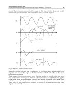
We first illustrate the output densities of a single film versus frequency
and incident
angle
with Fig.12 (a) for
R
S and (b) for
T
S . Evidently in terms of their respective maxima,
R
S is weaker than
T
S by about ten times. Their maxima both are situated at the second
resonant frequency
2
and correspond to the situation of normal incidence. The figure of
R
S is more complicated than that of
T
S since additional weaker peaks of
R
S are seen at
large incident angles.
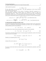
Next we discuss the SH outputs of SiO
2
/MnF
2
/air shown in Fig.13. Incident wave I and
reflective wave R are in the SiO
2
medium and transmission wave T in air. The maximum
peak of
R
S is between the two resonant frequencies and in the region of
o
41.3
c
. For
the given parameters, this angle just satisfies
21
sin /
c
and is related to
0
0
y
k
, so it
can be called a critical angle. When
c
,
0
y
k
is an imaginary number and transmission T
vanishes. For
c
,
R
S is very weak and numerically similar to that of the single film.
However, the maximum of
T
S is about four times as large as that of
R
S , and
T
S decreases
rapidly as the incident angle or frequency moves away from
c
or the resonant frequency
region. We find that the maxima of
R
S and
T
S are in intensity higher than those shown in
Fig.12 by about 40 and 13 times, respectively.
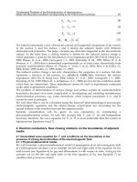
Finally we discuss the SH outputs of ZnF
2
/MnF
2
/air, with the dielectric constant of ZnF
2
larger than that of SiO
2
. The spectrum of S
R
is the most complicated and interesting, as
shown in Fig.14 (a). First we see two special angles of incidence. The first angle has the same
definition as
c
in the last paragraph and is equal to 20.1
o
. The second defined as
c
corresponds to 0
y
k
and is equal to 55
o
. For
c
,
y
k becomes an imaginary number
Electromagnetic Waves Propagation in Complex Matter
90
Fig. 12. SH outputs of a single AF film (MnF
2
film),
R
S and
T
S versus the incident angle
and frequency. After Zhou & Wang, 2008.
Fig. 13. SH outputs of SiO
2
/MnF
2
/air,
R
S and
T
S versus the incident angle and frequency.
After Zhou & Wang, 2008.
and the incident wave I is completely reflected, so the SH wave is not excited. On this point,
Fig.13(a) is completely different from Fig.12(a). More peaks of S
R
appear between the two
critical angles, but the highest peak stands between the two resonant frequencies and is near
to
c
. Outside of the region between
c
and
c
, we almost cannot see S
R
. For S
T
, the pattern
is more simple, as shown in Fig.14 (b). Only one main peak is seen clearly, which arises at
c
and occupies a wider frequency range. Different from Fig.13, the maxima in Fig.14(a)
and Fig.14(b) are about equal. Comparing Fig.14 with Fig.12, we find that the maximums of
S
R
and S
T
are larger than those shown in Fig.12 by about 240 times and 20 times,
respectively.
For the SH output peaks in Fig.13 and Fig.14, we present the explanations as follows. The
pump wave in the film is composed of two parts, the forward and backward waves
corresponding to the signs + and
- in Eq.(5-3), respectively. The transmission (T) vanishes
and the forward wave is completely reflected from the bottom surface of the film as
0
y
k
is
equal to zero or an imaginary number. In this situation, the backward wave as the reflection
wave is the most intense and equal in intensity to the forward wave. The interference of the
two waves at the bottom surface makes the pump wave enlarged, and further leads to the
appearance of the
s
T -peak in the vicinity of the critical angle
c
. The intensity of
s
R ,
however, depends on that of the pump wave at the upper surface. When the phase
difference between the forward and backward waves satisfies 2k
(k is an integer) at
Nonlinear Propagation of Electromagnetic Waves in Antiferromagnet
91
the surface, the interference results in the peaks of
s
R . Thus the interference effect in the
film plays an important role in the enhancement of the SHG.
Fig. 14. SH outputs of ZnF
2
/ MnF
2
/air,
R
S and
T
S versus the incident angle and frequency.
After Zhou & Wang, 2008.
Fig. 15. SH outputs of SiO
2
/MnF
2
/air.
R
S and
T
S versus the film thickness for
1
9.84cm
and
41.3
. After Zhou & Wang, 2008.
Electromagnetic Waves Propagation in Complex Matter
92
It is also interesting for us to examine the SH outputs versus the film thickness. We take the
SiO
2
/MnF
2
/air as an example and show the result in Fig.15. We think that the SH fringes
result from the change of optical thickness of the film, and the SH outputs reache their
individual saturation values about at 800dm
, 0.09 W/cm
2
, and 0.012 W/cm
2
. If we
enhance the incident wave density to 10.0kW/cm
2
, the two output densities are increased by
100 times, to 9.0W/cm
2
and 1.2W/cm
2
, or if we focus S
I
on a smaller area, higher SH outputs
are also obtained, so it is not difficult to observe the SH outputs.
If we put this AF film into one-dimension Photonic crystals (PCs), the SHG has a higher
efficiency(Zhou, et. al., 2009). It is because that when some AF films as defect layers are
introduced into a one-dimension PC, the defect modes may appear in the band gaps. Thus
electromagnetic radiations corresponding to the defect modes can enter the PC and be
greatly localized in the AF films. This localization effect has been applied to the SHG from a
traditional nonlinear film embedded in one-dimension photonic crystals(Ren, et. Al., 2004 ;
Si, et. al., 2001 ; Zhu, et.al., 2008, Wang, F., et. al. 2006), where a giant enhancement of the
SHG was found.
6. Summary
In this chacter, we first presented various-order nonlinear magnetizations and magnetic
susceptibilities of antiferromagnets within the perturbation theory in a special geometry,
where the external magnetic field is pointed along the anisotropy axis. As a base of the
nonlinear subject, linear magnetic polariton theory of AF systems were introduced,
including the effective-medium method and transfer-matrix-method. Here nonlinear
propagation of electromagnetic waves in the AF systems was composed of three subjects,
nonlinear polaritons, nonlinear transmition and reflection, and second-harmonic generation.
For each subject, we presented a theoretical method and gave main results. However,
magnetically optical nonlinearity is a great field. For AF systems, due to their infrared and
millimeter resonant-frequency feature, they may possess great potential applications in
infrared and THz technology fields. Many subjects parallel to the those in the traditional
nonlinear optics have not been discussed up to now. So the magnetically nonlinear optics is
a opening field. We also hope that more experimental and theoretical works can appear in
future.
7. Acknowledgment
This work is financially supported by the National Natural Scienc Foundation of China with
grant no.11074061 and the Natural Science Foundation of Heilongjiang Province with grant
no.ZD200913.
8. References
Almeida, N. S. & Mills, D. L.(1987); Nonlinear Infrared Response of Antiferromagnets. Phys.
Rev. B. Vol.36, (1987), pp.2015-2023.
Almeida, N. S. & Mills, D. L.(1988). Effective-medium Theory of Long-wavelength Spin
Waves in Magnetic Superlattices, Phys. Rev. B, Vol.38, (1988), pp.6698–6710.
Nonlinear Propagation of Electromagnetic Waves in Antiferromagnet
93
Almeida, N. S. & Tilley, D. R.(1990). Surface Poaritons on Antiferromagnetic Supperlattices,
Solid State Commun., Vol.73, (1990), pp.23-27.
Bai, J.; Zhou, S.; Liu, F. L. & Wang, X. Z.(2007). Nonlinear Infrared Transmission Through
and Reflection Off Antiferromagnetic Films. J. Phys.: Condens. Matters, Vol.19, (
2007), pp.046217-046227.
Balakrishnan,R. ; Bishop, A. R. & Dandoloff, R.(1992). Geometric Phase in the Classical
Continuous Antiferromagnetic Heisenberg Spin Chain, Phys. Rev.Lett. Vol.64,
(1990), pp.2107-2110; Anholonomy of a Moving Space Curve and Applications to
Classical Magnetic Chains,Phys. Rev. B Vol. 47, (1992), pp.3108-3117.
Balakrishnan, R. & Blumenfeld, R.(1997). On the Twist Excitations in a Classical Anisotropic
Antiferromagnetic Chain, Phys. Lett. A, Vol.237, (1997), pp.69-72.
Barnas, J.(1988). Spin Waves in Superlattices. I General Dispersion Equations for Exchange
Magnetostatic and Retarded Modes, J. Phys. C: Solid state Phys, Vol. 21,(1988) pp.
1021-1036.
Boardman, A. & Egan, P. (1986). Surface Wave in Plasmas and Solids, Vukovic, S. (Ed.), 3,
World Publ., Singapore.
Born, M.; Wolf, E.(1964), Principles of optics: electromagnetic theory of propagation, interference
and diffraction of light. Oxford, Pergamon Press.
Camley, R. E. & Mills, D. L.(1982). Surface-Polaritons on Uniaxial Antiferromagnets, Physical
Review B, Vol.26 No.3, (1982), pp. 1280-1287.
Camley, R. E.; Cottam, M. G. & Tilley, D. R.(1992). Surface-Polaritons in Antiferromagnetic
Superlattices with Ordering Perpendicular To the Surface, Solid State
Communications, Vol.81 No.7, (February 1992), pp. 571-574.
Cao, S. & Caillé, A.(1982). Polaritons Guides Dans Une Lame Antiferromagnetique, Solid
State Commun. Vol. 43, No.6, (August, 1982), pp.411-413.
Costa, B. V. ; Gourea M. E. & Pires, A. S. T.(1993). Soliton Behavior in an Antiferromagnetic
Chain, Phys. Rev.B Vol. 47, (1993), pp.5059-5062.
Daniel, M. & Bishop, A. R.(1992). Nonlinear Excitations in the Classical Continuum
Antiferromagnetic Heisenberg Spin Chain, Phys. Lett. A, Vol.162, (1992), pp.162-
166.
Daniel, M. & Amuda, R.(1994). On the Spin Excitations in the Classical Continuum
Heisenberg Antiferromagnetic Spin Systems, Phys. Lett. A, Vol.191, (1994),
pp.46-56.
Dumelow, T. &Tilley, D. R.(1993). Optical Properties of Semiconductor Superlattices in the
Far Infrared, J. Opt. Soc. Amer. A, Vol.10, (1993), pp.633-645.
Elmzughi, F.G.; Constantinou, N. C. & Tilley, D.R.(1995a). The Effective-medium
Theory of Magnetoplasma Superlattices, J. Phys.: Condens. Matter, Vol. 7, (1995),
pp.315-326.
Elmzughi, F. G.; Constantinou, N. C. & Tilley, D. R.(1995b). Theory of Electromagnetic
Modes of a Magnetic Superlattice in a Transverse Magnetic Field: An Effective-
Medium Approach, Phys. Rev. B, Vol.51, (1995), pp.11515-11520.
Fiebig, M.; Frohlich, D.; Krichevtsov, B. B. & Pisarev, R. V.(1994). Second Harmonic
Generation and Magnetic-Dipole-Electric-Dipole Interference in Antiferromagnetic
Cr
2
O
3
, Phys. Rev. Lett. , Vol. 73, (1994), pp.2127-2130.
Electromagnetic Waves Propagation in Complex Matter
94
Fiebig, M.; Frohlich, D.; Lottermoser, T.; Pisarev, R. V. & Weber, H. J.(2001). Second
Harmonic Generation in the Centrosymmetric Antiferromagnet NiO, Phys. Rev.
Lett. Vol.87, (2001), pp.137202.
Fiebig, M.; Pavlov, F V. V. & Pisarev, R. V. (2005). Second-Harmonic Generation as a Tool
for Studying Electronic and Magnetic Structures of Crystals: Review, J. Opt. Soc.
Am. B, Vol.22, (2005), pp.96-118.
Jensen,M. R. F.; Parker,T. J.; Abraha, K. & Tilley, D. R.(1995). Experimental Observation of
Magnetic Surface Polaritons in FeF
2
by Attenuated Total Reflection, Phys. Rev. Lett.
Vol,75, (1995),pp.3756–3759.
Kahn,L.; Almeida, N. S. & Mills, D. L.(1988). Nonlinear Optical Response of Superlattices:
Multistability and Soliton Trains, Phys. Rev. B, Vol.37, (1988), pp.8072-8081.
Klingshirn, C. F. (1997), Chapter3, In: Semiconductor Optics, Springer, Berlin.
Lighthill, M. J.(1965). Contributions to the Theory of Waves in Nonlinear Dispersive
Systems, J. Inst. Math. Appl. Vol.1, (1965),pp.269-306.
Lim, S. C.; Osman, J. & Tilley, D. R.(2000). Calculations of Nonlinear Magnetic Susceptibility
Tensors for a Uniaxial Antiferromagnet. J. Phys. D, Applied Physics, Vol.33, (2000),
pp.2899-2910.
Lim, S. C.(2002). Magnetic Second-harmonic-generation of an Antiferromagnetic Film, J.
Opt. Soc. Am. B, Vol.19, (2002), pp.1401-1410.
Lim, S. C.(2006). Second Harmonic Generation of Magnetic and Dielectric Multilayers, J.
Phys.: Condens. Matter, Vol.18, (2006), pp.4329-4343.
Morrish, A. H. (2001). The Physical Principles of Magnetism, Wiley-IEEE Press, ISBN 978-0-
7803-6029-7.
Oliveros, M. C.; Almeida, N. S.; Tilley, D. R.; Thomas, J. & Camley, R. E.(1992).
Magnetostatic Modes and Polaritons in Antiferromagnetic Nonmagnetic
Superlattices. Journal of Physics-Condensed Matter, Vol.4, No.44, (November 1992),
pp. 8497-8510.
Raj, N. & Tilley, D. R.(1987). Polariton and Effective-medium Theory of Magnetic
Superlattices, Phys. Rev. B, Vol.36, (1987), pp.7003–7007.
Raj, N. & Tilley, D. R.(1989), The Electrodynamics of Superlattices, Chapter 7 of The
Dielectric Function of Condensed Systems. Elsevier, Amsterdam.
Ren, F. F. ; Li, R. ; Chen, C. ; Wang, H. T. ; Qiu, J. ; Si, J. & Hirao, K.(2004). Giant
Enhancement of Second Harmonic Generation in a Finite Photonic Crystal with a
Single Defect and Dual-localized Modes, Phys. Rev. B, Vol.70, (2004), pp. 245109 (4
pages).
Stamps, R. L. & Camley, R. E.(1996). Spin Waves in Antiferromagnetic Thin Films
and Multilayers: Surface and Interface Exchange and Entire-Cell Effective-
Medium Theory. Physical Review B, Vol.54, No. 21, (December 1996), pp. 15200-
15209.
Shen, Y. R.(1984), The Princinples of Nonliear Optics, (Wiley), pp. 86-107.
Si, B ; Jiang, Z. M. & Wang, X.(2001). Defective Photonic Crystals with Greatly Enhanced
Second-harmonic Generation, Opt. Lett. Vol. 26, (2001), pp.1194-1196.
Nonlinear Propagation of Electromagnetic Waves in Antiferromagnet
95
Song, Y. L.; Ta, J. X ; Li, H. & Wang, X. Z.(2009). Presence of Left-handness and Negative
Refraction in Antiferromagnetic/ionic-crystal Multilayered Film, J. Appl. Phys.
Vol.106, (2009) pp. 063119.
Ta, J. X.; Song, Y. L. & Wang, X. Z. (2010), Magneto-phonon Polaritons of
Antiferromagnetic/ion-crystal Superlattices, J. Appl. Phys. Vol.108, (2010)
pp.013520 (4 pages).
Vukovic, S.; Gavrilin, S.N. & Nikito, S.A.(1992). Bistability of Electromagnetic Waves in an
Easy-Axis Antiferromagnet Subjected to a Static Magnetic Field. Phys. Solid State.,
Vol.34, (1992), pp.1826-1828.
Wang, F. ; Zhu, S. N. ; Li, K. F. & Cheah, K. W.(2006). Third-harmonic Generation in a One-
dimension Photonic-crystal-based Amorphous Nanocavity, Appl. Phys. Lett. Vol.88,
(2006), pp.071102 (3 pages).
Wang, Q. & Awai, I.(1998). Frequency Characteristics of the Magnetic Spatial Solitons on the
Surface of an Antiferromagnet. J. Appl. Phys. Vol.83, (1998), pp.382-387.
Wang,Q.; Wu,Z.; Li, S. & Wang, L.(2000). Nonlinear Behavior of Magnetic Surface Waves on
the Interface between Ferromagnet and Antiferromagnet. J. Appl. Phys., Vol.87,
(2000), pp.1908-1913.
Wang, J. J. ; Zhou, X. F.; Wan, W. L. & Wang, X. Z, Transmission by Antiferromagnetic-
Nonmagnetic Multilayers, J. Phys.: Condens Matter, Vol. 11,(1999) pp. 2697-
2705.
Wang, X. Z. & Tilley D. R.(1987). Retarded Modes of a Lateral Antiferromagnetic
/nonmagnetic Superlattice, Phys. Rev. B, Vol.52, No. 18, (November 1987),
pp.13353–13357.
Wang, X. Z. & Fu, S. F.(2004). Dispersion Properties of Nonlinear Bulk Polaritons in Uniaxial
Antiferromagnetic/nonmagnetic Superlattices J. Magn. Magn. Mater. Vol.271,
(2004), pp.334-347.
Wang, X. Z. & Li, H.(2005). Nonlinear Polaritons in Antiferromagnetic /Nonmagnetic
Superlattices. Phy. Rev. B, Vol.72, (2005), pp.054403-054412.
Wright, E.; Stegeman, G. (1992). Nonlinear planar waveguide. Anisotropic & nonlinear opt.
waveguide, Elsevier Science Publisher B. V., pp.117.
Zhou, S.; Li, H.; Fu, S. F. & Wang, X. Z.(2009). Second Harmonic Gerneration from an
Antiferromagnetic Film in One-dimensional Photonic Crystals. Phys. Rev. B, Vol.80,
(2009), pp.205409 (12 pages).
Zhou, S.; Wang, X. Z.(2008). A Method of Enhancing Second-Harmonic Generation of
Antiferromagnetic Film. Journal of the Optical Society of America B, Vol.25, (2008),
pp.1639~1644.
Zhou, S.(2010). Magnetically optical nonlinearity of antiferromagnetic/dielectric
systems, Doctorial thesis, Ch.5 (Harbin University of Science and
Technology,2010).
Zhu, N. & Cao, S.(1987). Magnetic Polaritons in Antiferromagnetic/
nonmagnetic Multilayers, Physics Letters A, Vol. 124, No.9, (October, 1987), pp.
515-522.
Electromagnetic Waves Propagation in Complex Matter
96
Zhu, Q. ; Wang, D. & Zhang, Y.(2008). Design of Defective Nonlinear Photonic Crystals for
Multiple Wavelengths' Second Harmonic Generation, J. Opt. A: Pure Appl. Opt.
Vol.10, (2008), pp.025201 (4 pages).
4
Quasi-planar Chiral Materials
for Microwave Frequencies
Ismael Barba
1
, A.C.L. Cabeceira
1
, A.J. García-Collado
2
,
G.J. Molina-Cuberos
2
, J. Margineda
2
and J. Represa
1
1
University of Valladolid
2
University of Murcia
Spain
1. Introduction
The growing development in the new communication technologies requests devices to
perform new features or to improve the old ones. The trend is to develop new artificial
materials reproducing well-known properties already present in other frequency ranges
(such as optics) or materials with properties inexistent in the nature. Among the first kind,
artificial chiral media, based on the random inclusion of metallic particles with chiral
symmetry into a host medium are worth to mention (Fig. 1). Nevertheless, the fabrication
techniques up-to-date are quite expensive and produce samples not easy to be tailored and
with imperfections, such as intrinsic anisotropy and non-homogeneity (non-uniform density
and orientation of inclusions), as well as heavy losses.
Fig. 1. Helix-based artificial chiral material. The sample is a 30 cm diameter disk fabricated
by dispersion of six-turn stainless-steel helices in an epoxy resin with a low curing
temperature. The helices are 2 mm height and 1.2 mm outer diameter.
During the last years, alternative methods, based on a periodic distribution of planar or
quasi-planar chiral particles, have been proposed. This alternative presents the possibility of
using conventional printed-circuit fabrication techniques to manufacture the structure. At
the same time, the use of via holes provides additional flexibility to select the type of
Electromagnetic Waves Propagation in Complex Matter
98
inclusions from helices to cranks or even pseudo-chiral inclusions such as ’s. As a
consequence, the realization of the bulk material, staggering printed circuit plates, gives rise
to axial anisotropy.
In this chapter, we are going to present some of the research performed during the last years
in the field of chiral materials implementation by means of quasi-planar technologies.
Section 2 presents an introduction on chiral materials, as well as (2.2) different approaches in
order to implement them: traditional (random) distribution and new, periodic distributions.
In the last case, we present different alternative (planar) implementations, finishing with our
own (quasi-planar) proposal.
Section 3 shows the two complementary analysis techniques we have employed: numerical
analysis, as well as experimental measures, both in free and guided propagation, with a
previous fabrication of the samples. Finally, we present (section 4) the results we have
obtained (rotation angle of polarization).
2. Chiral materials
Chiral materials are characterized by asymmetric microstructures in such a way that those
structures and their mirror images are not superimposable. As a consequence, right- and
left-hand circularly polarized waves propagate through the material with different phase
velocities and, in case the medium is lossy, absorption rates. Electromagnetic waves in chiral
media show the following interesting behavior (Lindell et al., 1994):
1. Optical (electromagnetic) rotatory dispersion (ORD), causing a rotation of polarization;
2. Circular dichroism (CD): due to the different absorption coefficients of a right- and left-
handed circularly polarized wave, the nature of field polarization is modified, making
linear polarization of a wave to change into elliptical polarization.
These properties have drawn considerable attention to chiral media and may open new
potential applications in microwave and millimeter-wave technology: antennas and arrays
(Lakhtakia et al., 1988; Viitanen et al., 1998), twist polarizers (Lindell et al., 1992),
antireflection coatings (Varadan et al., 1987; Kopyt 2010), etc. It has been also proposed as a
way to achieve negative refraction index (Pendry, 2004; Tretyakov et al., 2005). Also, many
papers on the analysis of free and guided electromagnetic wave propagation through chiral
media have been published, both in time (González-García et al., 1998; Demir et al., 2005;
Pereda et al., 2006) and frequency (Xu et al., 1995; Alú et al., 2003; Pitarch et al., 2007; Gómez
et al., 2010) domain. For this reason, during the last years, there has been an extensive
research on new designs that enhance the above-mentioned properties, as we will see in the
next sections of this chapter.
2.1 Constitutive relationships
In contrast to isotropic materials, characterized by their permittivity and permeability, bi-
isotropic materials show a cross coupling between electric and magnetic fields, their
constitutive relations being:
DEH
BEH
(1)
where the four scalars
are function of frequency . When the following condition
holds:
Quasi-planar Chiral Materials for Microwave Frequencies
99
0
j
c
(2)
c
0
being light speed in vacuum, the medium is said to be “chiral”. The parameter is the
“chirality” or “Pasteur” parameter (Lindell et al., 1994). In the frequency domain, this leads
to the following constitutive relationships:
0
0
j
DE H
c
j
BH E
c
(3)
The real part of the chirality parameter is related with the rotation angle of the polarization
plane (ORD) in a distance d by means of the following expression:
0
'
2d
c
(4)
Considering electromagnetic field propagation through a homogeneous chiral medium, it is
convenient to introduce new field variables,
E
and
H
(“wavefield vectors”), being the
following linear combinations of the electric and magnetic fields:
1
2
EE
j
ZH
,
1
2
j
HHE
Z
(5)
where Z is the wave impedance of the medium,
Z . Actually, the two wavefields
{
E
,
H
} and {
E
,
H
} are plane right-circularly and left-circularly polarized waves,
respectively. The advantage of introducing these new vectors is that they satisfy the
Maxwell equations in an equivalent isotropic medium, so we may use well-known solutions
for fields in simple isotropic medium to obtain solutions for wave propagation through
chiral media (Lindell et al., 1994). These wavefield vectors will “see“ equivalent simple
isotropic media with the equivalent parameters:
1
,
1
(6)
It is clear that, if is high enough, one of the wavefield vectors correspond to a backward
wave (Tretyakov et al., 2005). That means that, for one of the two possible circularly
polarized waves, travelling through a highly chiral material, this one behaves as a left-
handed (Veselago) metamaterial.
2.2 Chiral implementations
2.2.1 Random distributions
Traditionally, artificial chiral media at microwave frequencies are fabricated by embedding
conducting helices into a host, as shown in Fig 1. The dimensions of these helices determine
the bandwidth where the optical activity takes place (Lindman, 1920; Tretyakov et al., 2005).
Nevertheless, chirality is a geometrical aspect, therefore helices are not the only possibility,
Electromagnetic Waves Propagation in Complex Matter
100
so other type of inclusions, like metal cranks (Molina-Cuberos et al., 2009; Cloete et al.,
2001) have been proposed also; an example may be seen in Fig. 2.
Fig. 2. Crank-based artificial chiral material. Chiral elements were produced from a 0.4 mm
diameter and 12.6 mm length copper wire by bending in three segments by two 90 angles,
all with the same handedness. The elements were dispersed in an epoxy resin with a low
curing temperature (Molina-Cuberos et al., 2009).
In any case, it is necessary to be careful with the fabrication procedure to assure isotropy
and homogeneity. The inclusions must be randomly oriented with no special direction. If
the particles are placed in an aligned configuration, the result is a macroscopically
bianisotropic material, leading to matrix coefficients for the constitutive parameters (Lindell
et al., 1994). Also, a random distribution trends to present local density variations and
accidental alignments (see detail in Fig. 1), which causes spatial variations of the constitutive
relationships. At the same time, this procedure involves other drawbacks like high cost and
difficulty in cutting and molding the material.
In the case of random distribution of cranks, the problems associated to the lack of
homogeneity are enhanced. For the same total wire length cranks are bigger than helices,
which makes the number density of cranks to be lower than the one using helices and
increases the inhomogeneity. Molina-Cuberos et al. (2009) found fluctuations of the
transmitted wave depending on the sample position and orientation with respect to the
antenna. Therefore, several measurements and a mean value of the rotation angle were
carried out.
Quasi-planar Chiral Materials for Microwave Frequencies
101
2.2.2 Periodical distributions
The problems associated to the lack of homogeneity in chiral media based on random
distribution of particles as helices or cranks can be reduced or even eliminated by designing
periodical lattices. By an adequate distribution of metallic cranks is possible to build chiral
media with homogeneous, isotropic and reciprocal behavior at microwave range (García-
Collado et al., 2010), Fig. 3 shows an example of such medium.
Fig. 3. Detailed view of a periodical lattice of cranks with the same handedness produced
from 0.68 mm diameter and 15 mm length copper wire by bending in three segments by two
90 degrees angles. One of the segments is introduced perpendicularly into the host medium,
polyurethane foam with a relative permittivity close to one. The backside of the medium is
completely free of metal. Right: photograph of the lattice (García-Collado et al., 2010). Left:
MEFIsTo
TM
model in which we may see the geometry of the cranks
For these reasons, alternative methods of manufacturing chiral materials have been
proposed in recent years: Pendry et al. (Pendry et al.; 2004) proposed a periodical
distribution of twisted Swiss-rolls, Kopyt et al. (Kopyt et al.; 2010) a distribution of chiral
honeycombs. Nevertheless, most of the alternatives rely on planar and quasi-planar
technologies, like Printed Circuit Board (PCB) technology, or even integrated circuit
technology, for THz and optical materials. They provide a low-cost technique, which allows
a high flexibility in the design of the elementary cell.
Planar technologies make use of two-dimensional elements, in order to obtain media with
chiral response. The general concept of chirality, from a geometrical point of view, can be
defined in a plane geometry (two dimensions): a structure is considered to be chiral in a
plane if it cannot be brought into congruence with its mirror image, unless it is lifted from
the plane (Le Guennec, 2000a, 2000b). In this case, it is possible to design a 2D-chiral
medium consisting on flat elements possessing no line of symmetry in the plane, and which
allows the use of planar technology to manufacture it.
However, electromagnetic activity (electromagnetic rotatory dispersion and circular
dichroism) is a phenomenon that takes place in the three dimensional space. Some authors
have tried to find electromagnetic activity in thus 2D structures: Papakostas et al. (2003)
found a rotation of the polarization plane of a wave incident on a 2D-chiral planar structure
like showed in Fig. 4, remarking its apparently nonreciprocal nature: when observed from
the back side instead of the front, the sense of the twist is reversed, suggesting then a
nonreciprocal polarization rotation similar to that observed in the Faraday effect. That
interpretation of this result has opened a discussion on the possibility of a violation of
reciprocity and time reversal symmetry (Schwanecke et al., 2003). Kuwata-Gonokami et al.
Electromagnetic Waves Propagation in Complex Matter
102
(2005) concluded that such structures are actually chiral in 3D (taking into account air-metal
and substrate-metal interfaces), and their electromagnetic activity must arise from this three
dimensional nature.
Fig. 4. Planar chiral structure made by arrays of gammadions arranged in two-dimensional
square gratins (Papakostas et al., 2003).
Other groups have achieved three-dimensional chirality by means of multilayered
structures of plane elements. The elements may be 2D-chiral (Rogacheva et al., 2006; Plum et
al., 2007, 2009) or even non chiral (Zhou et al., 2009): in both cases, the 3D-chirality is
obtained by means of a twist between layers (Fig. 5). These structures resulted to give an
extremely strong rotation, as well as a negative index of refraction for one of the circularly
polarized waves.
Fig. 5. Left: schematic representation of a chiral “cross-wire” simple like the one studied by
Zhou et al. (2009). Right: schematic representation of a unit cell of a chiral structure,
constructed from planar metal rosettes separated by a dielectric slab (Rogacheva et al., 2006;
Plum et al., 2007, 2009)
Quasi-planar Chiral Materials for Microwave Frequencies
103
Finally, it is possible also to construct 3D chiral samples using of quasi-planar technology: in
this case, three dimensional PCB technology is employed, involving two-sided boards plus
the use of via holes to connect both sides of the board. Such approximation was proposed by
Marqués et al. (2007) and also by the authors of this chapter (Molina-Cuberos et al., 2009;
Barba et al., 2009).
Fig. 6. Photograph of a structure similar to the shown in Fig. 3, but manufactured by means
of Printed Circuit technology.
In our research, we have designed different chiral distributions of “molecules” and
implemented them by different means: one (Fig. 3) is made by using metal cranks
introduced into a polyurethane tablet; the second one (Fig. 6) is, as mentioned, made using
PCB technology. We have designed and analyzed different distributions; some of them have
been implemented and their behavior measured experimentally, while other ones have been
modeled using numerical techniques. More details may be read in the following sections.
3. Analysis
We have worked, first, with the numerical analysis of the designed materials, which allows
the study of their electromagnetic behavior at high frequency, previous to the effective
construction of the same ones. We have used two different commercially available software
in time domain:
a.
MEFiSTo
TM
, based on TLM method.
b.
CST Studio Suite
TM
2009, based on the finite integration technique (FIT).
Both methods are complete tools to solve electromagnetic problems in 3D, allowing the
graphic visualization of the electromagnetic field propagation and its interaction with
materials and boundaries during the simulation. The principal advantage of simulating in
the time domain is that it most closely resembles the real world. In our case, it allows to
obtain a very broadband data with a single simulation run with much less memory
requirements than required in frequency-domain methods.
The experimental set-up used is based on a previous one for permittivity and permeability
measurements at X-band (8.2 - 12.4 GHz) (Muñoz et al., 1998), and adapted to measure
electromagnetic activity (Molina-Cuberos et al., 2009; García-Collado et al., 2010). Fig. 7
Electromagnetic Waves Propagation in Complex Matter
104
shows a diagram of the experimental set-up, where the incident wave is linearly polarized
in the vertical direction.
Fig. 7. Schematic diagram of the free space setup for the experimental determination of the
rotation angle and the three constitutive parameters of isotropic chiral material in the X-
Band (not to scale).
The transmitting and receiving antennas are 10-dB-gain rectangular horns. An incident
beam is focused by an ellipsoidal concave mirror (30 cm x 26 cm), which produces a roughly
circular focal area of about 6 cm in diameter, which is lower than sample size, so that
diffraction problems are avoided with relatively small samples. The transmitting antenna is
placed at one of the mirror foci (35 cm) and the sample at the other one. The sample holder
is midway between the mirror and the receiving antenna and is able to rotate around the
two axes perpendicular to the direction of propagation. The receiving antenna, located at 35
cm from the sample, can rotate about the longitudinal axis, which allows the measurement
of the scattering parameters (S parameters) corresponding to any polar transmission. The
interested reader is referred to Muñoz et al. (1998), Gómez et al. (2008) and García-Collado
et al., (2010) for a detailed description of the measurement setup and technique. Here, we
briefly present the measurement process:
Fig. 8. Waveguide setup for the experimental determination of the rotation angle produced
by a chiral material in X-band. A cylindrical sample is located in the circular waveguide and
fed through port 1. The transmitted wave is measured in port 2 by a rotating connection,
which allows determining the component of the electrical field parallel to the TE
10
mode of
the rectangular wave.
Quasi-planar Chiral Materials for Microwave Frequencies
105
First a two-port “through-reflect-line”' (TRL) calibration is performed at the two waveguide
terminals of the network analyzer, PNA-L N5230A, where the antennas are connected.
Then, a time domain (TD) transform is used to filter out mismatches from the antennas,
edge diffraction effects, and unwanted multiple antenna-mirror-sample reflections or
reflections from other parts of the system by means of the ``gating'' TD option of the
network analyzer. The rotation angle of the transmitted polarization ellipse is defined as the
difference between the polarization direction of the incident wave and the direction of the
major axis of the transmitted elliptically polarized wave. Rotation can be determined by
looking for the minimum value of the transmitted wave or by measuring the transmission
coefficient for co- and cross-polarization, S
21CO
and S
21CR
(Balanis, 1989):
)cos(
SS
SS
tan
)cos(SSSSSSOB
)cos(SSSSSSOA
CRCO
CRCO
/
/
CRCOCRCOCRCO
/
/
CRCOCRCOCRCO
2
2
2
1
2
22
2
1
22
2
1
2121
2121
1
21
21
2
21
2
21
4
21
4
21
2
21
2
21
21
21
2
21
2
21
4
21
4
21
2
21
2
21
(7)
where OA and OB are the major and minor axes, respectively,
the phase difference
between S
21CO
and S
21CR
, and
the tilt of the ellipse, relative to the incident wave.
In principle, the precise angle of rotation cannot be determined by this measurement alone,
there is an uncertainty of
n2 , where n is an integer. To determine the angle uniquely, we
make use of measurements far away from the resonance range, where it is expected, and
found that the rotation angle goes to zero. Once the scattering coefficients are known, it is
also possible to retrieve the constitutive parameters (
,
,
) of the sample.
Fig. 9. Rotation angle produced by a random distribution of helices (Fig. 1) in a host, for
different helix densities (25 cm
-3
, 50 cm
-3
, 100 cm
-3
) and sample thickness (5 mm, 10 mm).
Electromagnetic Waves Propagation in Complex Matter
106
Several analyses of the chiral effects, by making use of waveguide setup, have been also
developed; see for example Brewitt-Taylor et al. (1999). In order to test the effect of metallic
cranks in waveguide, some samples were initially designed to produce chiral isotropic
materials with a resonance frequency at X-band and placed into a section of circular
waveguide. Fig. 8 shows the experimental set-up. The sample is excited in a rectangular
waveguide and fed to the circular waveguide through a rectangular-circular waveguide
transition, the dominant mode in the rectangular waveguide is TE
10
, and the polarization is
perpendicular to the resistive film of the transition which absorbs any cross-polarized field.
The dominant mode is TE
11
, in the empty circular waveguide, and HE±
11
in the
chirowaveguide. After the sample, a section of circular waveguide, which can rotate around
the longitudinal axis, is connected to a rectangular guide through a transition. The rotation
angle of the transmitted wave is obtained by measuring the minimum value of the
transmitted wave; we have found that this procedure is more accurate than the
determination of the maximum on the transmitted wave.
Fig. 10. Schematic illustration of an array of gammadions, chiral in 2D. Each gammadion is
assumed to be of copper, and occupies a square of 6x6 mm. There is a separation of 3 mm
between each gammadion. The board is 2.5 mm thick.
4. Results
4.1 Random distributions (helices)
Fig. 9 shows the rotation angle produced by a distribution of helices in a host medium for
densities ranging from 0 cm
-3
to 100 cm
-3
, the error bars showing the uncertainties in the
angle determination. Chiral elements are six-turn stainless-steel helices that are 2 mm long
and 1.2 mm in outer diameter. The elements were dispersed in an epoxy resin with a low