New Perspectives in Biosensors Technology and Applications Part 10 pdf
Bạn đang xem bản rút gọn của tài liệu. Xem và tải ngay bản đầy đủ của tài liệu tại đây (3.45 MB, 30 trang )
New Perspectives in Biosensors Technology and Applications
262
Huang, C. P., Li, Y. K. & Chen, T. M. (2007). A highly sensitive system for urea detection by
using CdSe/ZnS core-shell quantum dots. Biosens. Bioelectron., Vol. 22, No. 8,
(March 2007), pp. 1835–1838, ISSN 0956-5663
Hwang, C. G., Kim, S. H., Oh, J. H., Kim, M. R. & Choi, S. H. (2008). Reduction of Aromatic
Nitro Compounds on Pd Colloids Prepared by γ-Irradiation. J. Industr. Eng.Chem.,
Vol. 14, No. 6, (November 2008), pp. 864-868, ISSN 1226-086X
Hyeon, T., Han, S., Sung, Y., Park, K. & Kim, Y. (2003). High-Performance Direct Methanol
Fuel Cell Electrodes using Solid-Phase-Synthesized Carbon Nanocoils. Angew.
Chem. Int. Ed., Vol. 42, No. 36, (September 2003), pp. 4352–4356, ISSN 0926-3373
Islam, M. F., Rojas, E., Bergey, D. M., Johnson, A. T. & Yodh, A. G. (2003). High Weight
Fraction Surfactant Solubilization of Single-Wall Carbon Nanotubes in Water. Nano
Letters, Vol. 3, No. 2, (February 2003), pp. 269-273, ISSN 1530-6984
Jelly, R., Lewis, S. W., Lennard, C., Lim, K. F. & Almog, J. (2008). Lawsone: a novel reagent
for the detection of latent fingermarks on paper surfaces. Chem. Commun., Vol. 2008,
No. 30, (August 2008), pp. 3513-3515, ISSN 1364-548X
Jia, J. B., Wang, B. Q., Wu, A. G., Cheng, G. J., Li, Z. & Dong, S. J. (2002). A Method to
Construct a Third-Generation Horseradish Peroxidase Biosensor: Self-Assembling
Gold Nanoparticles to Three-Dimensional Sol-Gel Network. Anal. Chem., Vol. 74,
No. 9, (May 2002), pp. 2217-2223, ISSN 0003-2700
Jung, D. J., Piao, M. H., Oh, S. H., Woo, J. C. & Choi, S. H. (2010). Fabrication of
Chemiluminescence Sensor Based on Conducting Polymer@SiO
2
/Nafion
Composite Film. J. Nanosci. Nanotechnol., Vol. 10, No. 10, (October 2010), pp. 6855-
6858, ISSN 1533-4880
Kang, Y. & Taton, T. A. (2003). Micelle-Encapsulated Carbon Nanotubes: A Route to
Nanotube Composites. J. Am. Chem. Soc., Vol. 125, No. 19, (April 2003), pp. 5650–
5651, ISSN 0002-7863
Kim, K. I., Kang, H. Y., Lee, J. C. & Choi, S. H. (2009). Fabrication of MWNT ion liquid
electrode and its application for sensing phenolics in red wines. Sensors, Vol. 9, No.
9, (August 2009), pp. 6701-6714, ISSN 1424-8220
Kim, K. I., Lee. J. C., Kevin, R. & Choi, S. H. (2010). Immobilization of tyrosinase in
carboxylic- and carbonyl group-modified MWNT electrode and its application for
sensing phenolics in red wines. J. Nanosci. Nanotechnol., Vol. 10, No. 6, (June 2010),
pp. 3790-3798, ISSN 1533-4880
Kim, M. R. & Choi, S. H. (2009). One-Pot Synthesis of Pd-M/ZnO (M = Ag, Cu, and Ni)
Catalysts by γ-Irradiation and Their Use in Hydrogenation and Suzuki Reaction. J.
Nanomaterials, Vol. 2009, (February 2009), pp. 1-7, ISSN 1687-4110
Kim, O. K., Je, J., Baldwin, J. W., Kooi, S., Pehrsson, P. E. & Buckley, L. J. (2003).
Solubilization of Single-Wall Carbon Nanotubes by Supramolecular Encapsulation
of Helical Amylose. J. Am. Chem. Soc., Vol. 125, No. 15, (March 2003), pp. 4426–4427,
ISSN 0002-7863
Kim, S. H., Oh, J. H., Yoo, B., Jung, D. J., Piao, M. H. & Choi, S. H. (2008). Fabrication of
Chemiluminescence Sensor Based on the Funcinalized MWNT-Nafion Composite
Film. Adv. Mater. Res., Vol. 47-50, (June 2008), pp. 1474-1477, ISSN 1022-6680
Fabrication of Biosensors Using Vinyl Polymer-grafted Carbon Nanotubes
263
Kim, S. J., Oh, S. D., Lee, S. & Choi, S. H. (2008). Radiolytic Synthesis of Pd-M (M = Ag, Ni,
and Cu)/C Catalyst and Their Use in Suzuki-type and Heck-type Reaction. J.
Industr. Eng. Chem., Vol. 14, No. 4, (July 2008), pp. 449-456, ISSN 1226-086X
Kim, S. K., Ryu, J. H., Kwen. H. D. & Choi, S. H. (2010). Convenient Preparation of Ion-
Exchange PVdF Membrane by Radiation-Induced Graft Polymerization for a
Battery Separator. Polymer(Korea), Vol. 34, No. 2, (March 2010), pp. 126-132, ISSN
0379-153X
Kim, S. K., Kwen, H. D. & Choi, S. H. (2011). Fabrication of microbial biosensor based on the
QDs-MWNTs supports by one-step radiation reaction and detection of phenolic
compounds in red wines. Sensors, vol. 11, (January 2011), pp. 2001-2012, ISSN 1424-
8220
Kitano, H., Tachimoto, K. & Anraku,Y. (2007). Functionalization of single-walled carbon
nanotube by the covalent modification with polymer chains. J. Colloid Interface Sci.,
Vol. 306, No. 1, (February 2007), pp. 28-33, ISSN 0021-9797
Knight, A. W. (1999). A review of recent trends in analytical applications of electrogenerated
chemiluminescence. Trends Anal. Chem., Vol. 18, No. 1, (January 1999), pp. 47-62,
ISSN 0165-9936
Koide, S. & Yokoyama, K. (1999). Electrochemical characterization of an enzyme electrode
based on a ferrocene-containing redox polymer. J. Electroanal. Chem., Vol. 468, No.
2, (June 1999), pp. 193–201, ISSN 0022-0728
Kooi, S. E., Schlecht, U., Burghard, M. & Kern, K. (2002). Electrochemical Modification of
Single Carbon Nanotubes. Angew. Chem. Int. Ed., Vol. 41, No. 8, (April 2002), pp.
1353-1355, ISSN 1521-3773
Kranaster, R. & Marx, A. (2007). Increased single-nucleotide discrimination in allele-specific
polymerase chain reactions through primer probes bearing nucleobase and 2'-
deoxyribose modifications. Chem. Eur. J., Vol. 13, No. 21, (July 2007), pp. 6115-6122,
1521-3765
Kwon, S. Y., Whittaker, A. & Choi, S. H. (2011). Fabrication of non-enzymatic glucose sensor
based on MWNTs with bimetallic Pt-M (M= Ru and Sn) catalysts by radiolytic
deposition. Biosens. Bioelectron., submitted for publication (2010-11-08), ISSN 0956-
5663
Lee, Y. J., Kim, J. D. & Park, J. Y. (2009). CMOS-Integrable Enzyme-Free Amperometric
Cholesterol Nano-Biosensor for U-Health and POC Applications. Journal of the
Korean Physical Society, Vol. 54, No. 5, (May 2009), pp. 1769-1773, ISSN 0374-4884
Lee, Y. J. & Choi, S. H. (2010). Electrochemical phenol biosensor based on immobilization of
tyrosinase on poly(GMA-co-VFc)/MWNT electrode. Proceedings of the Korean society
of analytical sciences, Jeju, Korea, November 2010
Lei, Y., Chen, W. & Mulchandani, A. (2006). Microbial biosensors. Anal. Chim. Acta, Vol. 568,
No. 1-2, (May 2006), pp. 200–210, ISSN 0003-2670
Li, Y., Kotzeva, V. P. & Fray, D. J. (2006). Electrochemical performance of CdS nanomaterials
synthesized by microemulsion techniques. Materials Letters, Vol. 60, No. 21-22,
(September 2006), pp. 2743-2746, ISSN 0167-577X
Lin, K. C., Tsai, T. S., & Chen, S. M. (2010). Performing enzyme-free H
2
O
2
biosensor and
simultaneous determination for AA, DA, and UA by MWNT–PEDOT film. Biosens.
Bioelectron., Vol. 26, No. 2, (October 2010), pp. 608–614, ISSN 0956-5663
New Perspectives in Biosensors Technology and Applications
264
Lin, M. S. & Leu, H. J. (2005). A Fe
3
O
4
-Based Chemical Sensor for Cathodic Determination of
Hydrogen Peroxide. Electroanalysis, Vol. 17, No. 22, (November 2005), pp. 2068–
2073, ISSN 1521-4109
Liu, H., Mao, G. & Meng, S. (1992). Preparation and characterization of the polymer-
protected palladium—gold colloidal bimetallic catalysts. J. Mol. Catal., Vol. 74, No.
1-3, (July-August 1992), pp. 275-284, ISSN 1381-1169
Liu, P. (2005). Modifications of carbon nanotubes with polymers. Eur. Polym. J., Vol. 41, No.
11, (November 2005), pp. 2693-2703, ISSN 0014-3057
Male, K. B., Hrapovic, S. & Luong, J. H. T. (2007). Electrochemically-assisted deposition of
oxidases on platinum nanoparticle/multi-walled carbon nanotube-modified
electrodes. Analyst, Vol. 132, No. 12, (December 2007), pp. 1254-1261, ISSN 0003-
2654
Marras, S. A. E., Tyagi, S. & Kramer, F. R. (2006). Real-time assays with molecular beacons
and other fluorescent nucleic acid hybridization probes. Clin. Chim. Acta, Vol. 363,
No. 1-2, (January 2006), pp. 48-60, ISSN 0009-8981
Men, X. H., Zhang, Z. Z., Song, H. J., Wang, K. & Jiang, W. (2008). Functionalization of
carbon nanotubes to improve the tribological properties of poly(furfuryl alcohol)
composite coatings. Comp. Sci. Technol., Vol. 68, No. 3-4, (March 2008), pp. 1042-
1049, ISSN 0266-3538
Millan, K. M., Saraullo, A. & Mikkelsen, S. R. (1994). Voltammetric DNA Biosensor for
Cystic Fibrosis Based on a Modified Carbon Paste Electrode. Anal. Chem., Vol. 66,
No. 18, (September 1994), pp. 2943-2948, ISSN 0003-2700
Musameh, M., Wang, J., Merkoci, A. & Lin, Y. (2002). Low-potential stable NADH detection
at carbon-nanotube-modified glassy carbon electrodes. Electrochem. Commun., Vol.
4, No. 10, (October 2002), pp. 743-746, ISSN 1388-2481
Niu, S. Y., Wu, M. L., Hu, L. Z., Mei, Z. H. & Liu, S. F. (2009). Nucleic acid biosensor for
DNA hybridization detection using rutin–Cu as an electrochemical indicator.
Electrochimica Acta, Vol. 54, No. 5, (February 2009), pp. 1564–1569, ISSN 0013-4686
Noffsinger, J. B. & Danielson, N. D. (1987). Liquid chromatography of aliphatic
trialkylamines with post-column chemiluminescent detection using tris(2,2′-
bipyridine)ruthenium(III). J. Chromatorgr. A, Vol. 387, (March 1987), pp. 520-524,
ISSN 0021-9673
Odaci, D., Timur, S. & Telefoncu, A. (2008). Bacterial sensors based on chitosan matrices.
Sens. Actuators B, Vol. 134, No. 1, (August 2008), pp. 89–94, ISSN 0925-4005
Oh, S. D., So, B. K., Choi, S. H., Gopalan, A., Lee, K. P., Yoon, K. R. & Choi, I. S. (2005).
Dispersing of Ag, Pd, and Pt–Ru alloy nanoparticles on single-walled carbon
nanotubes by γ-irradiation, Materials Letters, Vol. 59, No. 10, (April 2005), pp. 1121–
1124, ISSN 0167-577X
Oh, S. D., Choi, S. H., Gopalan, A., Lee, K. P. & Kim, S. H. (2006a). Radiolytic
Functionalization of Single- and Multi-Walled Carbon Nanotubes. J. Industr. Eng.
Chem., Vol. 12, No. 1, (January 2006), pp. 156-160, ISSN 1226-086X
Oh, S. D., Yoon, K. R., Choi, S. H., Gopalan, A., Lee, K. P., Sohn, S. H., Kang, H. D. & Choi, I.
S. (2006b). Dispersion of Pt–Ru alloys onto various carbons using γ-irradiation, J.
Non-Cryst. Solids, Vol. 352, No. 4, (April 2006), pp. 355–360, ISSN 0022-3093
Fabrication of Biosensors Using Vinyl Polymer-grafted Carbon Nanotubes
265
Oh, S. D., Kim, M. R., Choi, S. H., Chun, J. H., Lee, K. P., Gopalan, A. I., Hwang, C. G., Kim,
S. H. & Oh, J. H. (2008). Radiolytic Synthesis of Pd-M (M = Ag, Au, Cu, Ni and Pt)
Alloy Nanoparticles and Its Use in Reduction of 4-Nitrophenol. J. Industr.
Eng.Chem., Vol. 14, No. 5, (September 2008), pp. 687-692, ISSN 1226-086X
Park, K., Choi, J. H., Ahn, K. S. & Sung, Y. E. (2004). PtRu Alloy and PtRu−WO
3
Nanocomposite Electrodes for Methanol Electrooxidation Fabricated by a
Sputtering Deposition Method. J. Phys. Chem. B, Vol. 108, No. 19, (May 2004), pp.
5989–5994, ISSN 1089-5647
Park, S. J., Chung, T. D. & Kim, H. C. (2003). Nonenzymatic Glucose Detection Using
Mesoporous Platinum. Anal. Chem., Vol. 75, No. 13, (July 2003), pp. 3046–3049, ISSN
0003-2700
Patolsky, F., Weizmann, Y. & Willner, I. (2004). Long-Range Electrical Contacting of Redox
Enzymes by SWCNT Connectors. Angew. Chem. Int. Ed., Vol. 43, No. 16, (April
2004), pp. 2113-2117, ISSN 1521-3773
Piao, M. H., Yang, D. S., Yoon, K. R., Lee, S. H. & Choi, S. H. (2009). Development of an
Electrogenerated Chemiluminescence Biosensor using Carboxylic acid-
functionalized MWNT and Au Nanoparticles. Sensors, Vol. 9, No. 3, (March 2009),
pp. 1662-1677, ISSN 1424-8220
Piao, M. H., Son, P. S., Chang, C. H. & Choi, S. H. (2010). A glucose biosensor based on
deposition of glucose oxidase onto Au nanoparticles poly(maleic anhydride)-
grafted multiwalled carbon nanotube electrode. Anal. Sci. Tech., Vol. 23, No. 2,
(April 2010), pp. 165-171, ISSN 1225-0163
Qu, L. T., Dai, L. M. & Osawa, E. (2006). Shape/Size-Controlled Syntheses of Metal
Nanoparticles for Site-Selective Modification of Carbon Nanotubes. J. Am. Chem.
Soc., Vol. 128, No. 16, (April 2006), pp. 5523-5532, ISSN 0002-7863
Reddy, A. L. M. & Ramaprabhu, S. (2007). Pt/SWNT−Pt/C Nanocomposite Electrocatalysts
for Proton-Exchange Membrane Fuel Cells. J. Phys. Chem. C, Vol. 111, No. 44,
(November 2007), pp. 16138–16146, ISSN 1932-7447
Ryu, H. N. & Choi, S. H. (2010a). Tyrosinase-immobilized Biosensor Based on Ionic
Property-modified MWNTs Prepared by Radiation-induced Graft Polymerization.
Carbon Letters, Vol. 11, No. 3, (December 2010), pp. 216-223, ISSN 1976-4251
Ryu, H. N. & Choi, S. H. (2010b). Fabrication of electrochemiluminescence (ECL) sensor
based on sulfonic acid (-SO
3
H) functionalized carbon nanotube. Proceedings of the
Korean society of analytical sciences, Jeju, Korea, November 2010
Saito, T. & Watanabe, M. (1998). Characterization of poly(vinylferrocene-co-2- hydroxyethyl
methacrylate) for use as electron mediator in enzymatic glucose sensor. React.
Funct. Polym., Vol. 37, No. 1-3, (June 1998), pp. 263–269, ISSN 1381-5148
Saito, Y., Yoshikawa, T., Okuda, M., Fujimoto, N., Sumiyama, K., Suzuki, K., Kasuya, A. &
Nishina, Y. (1993). Carbon nanocapsules encaging metals and carbides. J. Phys.
Chem. Solids., Vol. 54, No. 12, (December 1993), pp. 1849-1860, ISSN 0022-3697
Seo, K. D., Oh, S. D., Choi, S. H., Kim, S. H., Park, H. G. & Zhang, Y. P. (2008). Radiolytic
loading of the Pt–Ru nanoparticles onto the porous carbons. Colloids Surf. A:
Physicochem. Eng. Aspects, Vol. 313–314, (February 2008), pp. 393–397, ISSN 0927-
7757
New Perspectives in Biosensors Technology and Applications
266
Shen, J., Huang, W., Wu, L., Hu, Y. & Ye, M. (2007). Study on amino-functionalized
multiwalled carbon nanotubes. Mater. Sci. Eng. A, Vol. 464, No. 1-2, (August 2007),
pp. 151-156, ISSN 0921-5093
Shen, X-C., Zhang, Z-L., Zhou, B., Peng, J., Xie, M., Zhang, M. & Pang, D-W. (2008). Visible
lightinduced plasmid DNA damage catalyzed by a CdSe/ZnS-photosensitized
nano-TiO
2
film. Environ. Sci. Technol., Vol. 42, No. 14, (July 2008), pp. 5049-5054,
ISSN 0013-936X
Shin, S. R., Kwen, H. D. & Choi, S. H. (2011). Fabrication of Electrochemical Microbial
Biosensor Based on MWNT Supports prepared by Radiation-Induced Graft
Polymerization, Polymer(Korea), submitted for publication (2010-09), ISSN 0379-
153X
Shumyantseva, V., Deluca, G., Bulko, T., Carrara, S., Nicolini, C., Usanov, S. & Archakov, A.
(2004). Cholesterol amperometric biosensor based on cytochrome P450scc. Biosens.
Bioelectron., Vol. 19, No. 9, (April 2004), pp. 971-976, ISSN 0956-5663
Song, Y. Y., Zhang, D., Gao, W. & Xia, X. H. (2005). Nonenzymatic Glucose Detection by
Using a Three-Dimensionally Ordered, Macroporous Platinum Template, Chem.
Eur. J., Vol. 11, No. 7, (March 2005), pp. 2177-2182, ISSN 1521-3765
Steigerwalt, E. S., Deluga, G. A. & Lukehart, C. M. (2002). Pt−Ru/Carbon Fiber
Nanocomposites: Synthesis, Characterization, and Performance as Anode Catalysts
of Direct Methanol Fuel Cells. A Search for Exceptional Performance. J. Phys. Chem.
B, Vol. 106, No. 4, (January 2002), pp. 760–766, ISSN 0022-3654
Sun, Y., Buck, H. & Mallouk, T. E. (2001). Combinatorial Discovery of Alloy Electrocatalysts
for Amperometric Glucose Sensors. Anal. Chem., Vol. 73, No. 7, (April 2001), pp.
1599–1604. ISSN 0003-2700
Sweeny, B. K. & Peters, G. G. (2001). Cyclic voltammetric study of the catalytic behavior of
nickel (I) salen electrogenerated at a glassy carbon electrode in an ionic liquid (1-
butyl-3-methylimidazolium tetrafluoroborate, BMIM+BF4−). Electrochem. Commun.,
Vol. 3, No. 12, (December 2001), pp. 712-715, ISSN 1388-2481
Tasis, D., Tagmatarchis, N., Georgakilas, V. & Prato, M. (2003). Soluble Carbon Nanotubes.
Chem. Eur. J., Vol. 9, No. 17, (September 2003), pp. 4000-4008, ISSN 0947-6539
Timko, M. P., Rushton, P. J., Laudeman, T. W., Bokowiec, M. T., Chipumuro, E., Cheung, F.,
Town, C. D. & Chen, X. F. (2008). Sequencing and analysis of the gene-rich space of
cowpea. BMC Genomics., Vol. 9, (February 2008), pp. 103-123, ISSN 1471-2164
Wang, J., Li, M., Shi, Z., Li, N. & Gu, Z. (2002a). Electrocatalytic Oxidation of
Norepinephrine at a Glassy Carbon Electrode Modified with Single Wall Carbon
Nanotubes. Electroanalysis,Vol. 14, No. 3, (February 2002), pp. 225-230, ISSN 1521-
4109
Wang, J., Li, M., Shi, Z., Li, N. & Gu, Z. (2002b). Direct Electrochemistry of Cytochrome c at a
Glassy Carbon Electrode Modified with Single-Wall Carbon Nanotubes. Anal.
Chem., Vol. 74, No. 9, (March 2002), pp. 1993-1997, ISSN 0003-2700
Wang, J. & Musameh, M. (2003a). Carbon Nanotube/Teflon Composite Electrochemical
Sensors and Biosensors. Anal. Chem., Vol. 75, No. 9, (March 2008), pp. 2075-2079,
ISSN 0003-2700
Fabrication of Biosensors Using Vinyl Polymer-grafted Carbon Nanotubes
267
Wang, J., Musameh, M. & Lin, Y. (2003b). Solubilization of Carbon Nanotubes by Nafion
toward the Preparation of Amperometric Biosensors. J. Am. Chem. Soc., Vol. 125,
No. 9, (February 2003), pp. 2408-2409, ISSN 0002-7863
Wang, J., Jina, S. & Wang, B. (2005). A new boronic acid fluorescent reporter that changes
emission intensities at three wavelengths upon sugar binding. Tetrahedron Lett., Vol.
46, No. 41, (October 2005), pp. 7003–7006, ISSN 0040-4039
Wang, J., Thomas, D. F. & Chen, A. (2008). Nonenzymatic Electrochemical Glucose Sensor
Based on Nanoporous PtPb Networks. Anal. Chem., Vol. 80, No. 4, (February 2008),
pp. 997–1004, ISSN 0003-2700
Wang, S. F., Wang, W. & Cai, H. C. (2005). Recognition and detection of dsDNA at a
thionalid self-assembled monolayer modified gold electrode. Sens. Actuator B:
Chem., Vol. 104, No. 1, (January 2005), pp. 8-14, ISSN 0925-4005
Wang, Y., Huang, J., Zhang, C., Wei, J. & Zhou, X. (1998). Determination of Hydrogen
Peroxide in Rainwater by Using a Polyaniline Film and Platinum Particles Co-
Modified Carbon Fiber Microelectrode. Electroanalysis, Vol. 10, No. 11, (September
1998), pp. 776–778, ISSN 1521-4109
Wang, Z. H., Liu, J., Liang, Q. L., Wang, Y. M. & Luo, G. (2002). Carbon nanotube-modified
electrodes for the simultaneous determination of dopamine and ascorbic acid.
Analyst, Vol. 127, No. 5, (May 2002), pp. 653-658, ISSN 0003-2654
Wightman, R. M., Curtis, C. L., Flowers, P. A., Maus, R. G. & McDonald, E. M. (1998).
Imaging Microelectrodes with High-Frequency Electrogenerated
Chemiluminescence. J. Phys. Chem. B., Vol. 102, No. 49, (December 1998), pp. 9991-
9996, ISSN 1089-5647
Xiao, F., Zhao, F., Zhang, Y., Guo, G. & Zeng, B. (2009). Ultrasonic Electrodeposition of
Gold−Platinum Alloy Nanoparticles on Ionic Liquid−Chitosan Composite Film and
Their Application in Fabricating Nonenzyme Hydrogen Peroxide Sensors. J. Phys.
Chem. C, Vol. 113, No. 3, (January 2009), pp. 849–855, ISSN 1932-7447
Yang, D. S., Jung, D. J. & Choi, S. H. (2010). One-step functionalization of multi-walled
carbon nanotubes by radiation-induced graft polymerization and their application
as enzyme-free biosensors. Radia. Phys. Chem., Vol. 79, No. 4, (April 2010), pp. 434–
440, ISSN 0969-806X
Yang, D. S., Sim, K. S., Kwen, H. D. & Choi, S. H. (2011). Radiolytic synthesis of Pt-Ru
catalysts based on functional polymer-grafted MWNT and their catalytic efficiency
for CO and MeOH. J. Nanomaterials, Vol. 2011, pp. 1-8, ISSN 1687-4110
Yang, J. H., Lee, J. C. & Choi, S. H. (2009). Tyrosinase-Immobilized Biosensor Based on the
Functionalized Hydroxyl Group-MWNT and Detection of Phenolic Compounds in
Red Wines. J. Sensors, Vol. 2009, (August 2009), pp. 1-9, ISSN 1687-725X
Yang, R., Qiu, X., Zhang, H., Li, J., Zhu, W., Wang, Z., Huang, X. & Chen, L. (2005).
Monodispersed hard carbon spherules as a catalyst support for the electrooxidation
of methanol. Carbon, Vol. 43, No. 1, (January 2005), pp. 11–16, ISSN 0008-6223
Yu, W., Liu, M., Liu, H. & Zheng, J. (1999). Preparation of Polymer-Stabilized Noble Metal
Colloids. J. Colloid Interf. Sci., Vol. 210, No. 1, (February 1999), pp. 218-221, ISSN
0021-9797
Zhang, L. & Fang, M. (2010). Nanomaterials in pollution trace detection and environmental
improvement. Nano Today, Vol. 5, No. 2, (April 2010), pp. 128-142, ISSN 1748-0132
New Perspectives in Biosensors Technology and Applications
268
Zhang, Y. J., Shen, Y. F., Li, J. H., Niu, L., Dong, S. J. & Ivaska, A. (2005). Electrochemical
Functionalization of Single-Walled Carbon Nanotubes in Large Quantities at a
Room-Temperature Ionic Liquid Supported Three-Dimensional Network Electrode.
Langmuir, Vol. 21, No. 11, (May 2005), pp. 4797-4800, ISSN 0743-7463
Zhao, Y., Zheng, W. D., Chen, H. & Luo, Q. M. (2002). Anodic oxidation of hydrazine at
carbon nanotube powder microelectrode and its detection. Talanta, Vol. 58, No. 3,
(September 2002), pp. 529-534, ISSN 0039-9140
13
Design and Fabrication of
3D Skyscraper Nanostructures and
Their Applications in Biosensors
Guigen Zhang
Department of Bioengineering, Department of Electrical and Computer Engineering
Institute for Biological Interfaces of Engineering 301, Rhodes Engineering Research Center
Clemson University Clemson, SC 29634
USA
1. Introduction
Biosensors are analytical devices that combine a biologically sensitive element with a
physical transducer to selectively and quantitatively detect the presence as well as the
amount of a specific compound in biological environments. The biosensitive element is for
target recognition and the physical transducer is for signal transduction. For the biosensitive
element, molecular couples such as antibody-antigen, protein-ligand, protein-aptamer,
paired-nucleotides and avidin-biotin are often used, and for the physical transducer
electrochemical methods such as voltammetric, impedimetric and amperometric
measurements are popular choices. For example, a sensing platform using the avidin-biotin
couple as the biosensitive element and an electrochemical technique as the physical
transducer has been widely explored to achieve rapid, specific and sensitive detections
(Ding et al., 2005; Hou et al., 2006, 2007; Lee et al., 2008).
Biosensors are important devices for monitoring biological species in various processes of
environmental, food, pharmaceutical and biomedical concerns. The main challenges many
biosensors face today include low sensitivity, poor specificity and proneness to fouling. The
advent of nanotechnology presents some promising solutions for alleviating these problems.
For example, improvements for the sensitivity and antifouling capability of biosensors have
been explored through the incorporation of nanostructures into the electrodes of biosensors
(Koehne et al., 2004; Wang et al., 2005; Anandan et al., 2006, 2007). Nanostructures like gold
nanotubes (Delvaux et al., 2003), carbon nanotubes (Gao et al., 2003; Wang et al., 2003, 2004)
and gold nanoparticles (Bharathi et al., 2001) have been incorporated into electrodes and
they exhibited much improved performance than conventional flat electrodes.
Biosensors using an electrochemical method as the underlying transducer offer a cost-
effective and more specific means to measure the electrical responses resulted from
electrochemical reactions between the sensitive element and the target analyte. In an
electrochemical based biosensor, the sensitivity is related to the surface area of its electrode
(Bard et al., 2001; Delvaux et al., 2003) because a large surface area is beneficial not only for
enzyme immobilization but also for electron transfer. The surface area of the electrode can
be increased by the use of nanostructures because the surface-to-volume ratio of a structure
New Perspectives in Biosensors Technology and Applications
270
increases as its size decreases (Jia et al., 2007; Anandan et al., 2007, Gangadharan et al., 2008).
Since most of these nanostructures are made of inorganic materials, to use them as
electrodes they have to be functionalized for biological recognition purposes (Gangadharan
et al., 2008; Lee et al., 2008). To functionalize these electrodes, biosensitive elements need to
be immobilized onto the electrode surface. In many situations, biosensitive molecules cannot
be immobilized directly onto the surface of these inorganic materials, thus anchoring
molecules are necessary. Therefore, the ability to improve the performance of these
inorganic-based nanostructured electrodes relies on not only the morphological design of
the nanostructures but also the selection of anchoring molecules, aside from the effects of
electrode reactions and the underlying mass transport mechanisms (Anandan et al., 2007).
To achieve high efficiency in enzyme immobilization on electrode surface, many techniques
have been developed including the use of self assembled monolayer (Gooding et al., 1998,
2000; Losic et al., 2001a, 2001b; Berchmans et al., 2003), conducting polymers (Uang et al.,
2002; Gao et al., 2003)
and sol-gels (Qiao et al., 2005). Among these methods, the self-
assembled monolayer (SAM) technique offers a better control for enzyme distribution at the
molecular level and a high degree of reproducibility in enzyme immobilization (Losic et al.,
2001a, 2001b; Berchmans et al., 2003). Physical entrapment of an enzyme in a porous
conducting polymer film at electrode surface offers an attractive alternative. Conducting
polymer like polypyrrole (PPy) can be electro- polymerized and deposited onto the
electrode surface to form a porous film, providing pores large enough for efficient electron
transfer (Ramanavicius et al., 2001; Gangadharan et al., 2008). Thus by mixing an enzyme in
pyrrole solution, a porous polymeric film with the enzyme entrapped inside can be formed
at electrode surface via electrodeposition.
However, the question remains unanswered is: how do these functionalization methods fare
in enhancing the sensing performance of electrodes made of three dimensional (3D) nano
structures? This chapter aims to seek an answer to this question. First, the design of high-
surface-area 3D nanostructures in a skyscraper metaphor is proposed for producing
structures with high surface on a limited projection area and the importance of having
sufficient mechanical robustness for the 3D skyscraper structures is discussed. Then,
methods to fabricate robust 3D skyscraper nanopillar structures in an aqueous process are
presented. Following that, electrochemical evaluations of these 3D nanopillar structures
having bare, molecularly treated, and functionalized surfaces are discussed. Finally, for
comparing the two functionalization methods, two cases are discussed in which the 3D
nanopillar structures are used as electrodes for glucose detection. In the first case, the 3D
electrodes are functionalized through a SAM/enzyme approach in which the biosensitive
enzyme (i.e., glucose oxidase, or GOx) is tethered to a SAM of anchoring molecules formed
at the electrode surface, and in the second case, the 3D electrodes are functionalized through
a PPy/enzyme approach in which GOx is entrapped in a porous film of PPy
electrodeposited at the electrode surface.
2. Design of high-surface-area nanostructures
Nanostructures such as nanorods, nanowires, nanotubes and nanoparticles have been
widely explored for application in biosensors because these structures offer large surface
areas in addition to their unique optical, electrical and mechanical properties. For example,
the use of carbon nanotubes (Wang et al., 2003, 2004; Gao et al., 2003), peptide nanotube
(Yemini et al., 2005) and nanoparticles (Bharathi et al., 2001) in various biosensors resulted in
Design and Fabrication of 3D Skyscraper Nanostructures and Their Applications in Biosensors
271
increased signal measurements. Electrodes modified with peptide nanotubes showed a 2.5-
fold increase in amperometric response when compared with non-modified electrodes.
Similarly, electrodes incorporated with carbon nanotubes showed a significant increase in
selectivity and sensitivity for glucose detection.
For r = 100 nm, h = 5 μm and p = 50%:
0
2
/1 51
h
SS p
r
=
+=
22
3/2 arp
π
=
22
0
33 33
/( 6)/( )
22
SS a rh a
π
=+
ha r
r
Packing density:
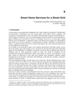
Fig. 1. Schematic illustration for increasing the overall surface area by building 3D
skyscraper structures on a limited areal footprint.
One reason for the performance improvement when nanostructures are used is that these
nanostructures provide large surface areas due to the fact that the surface-to-volume ratio of
a structure increases as its size decreases. But when these nanostructures are formed on a
planar substrate, the overall surface-area enhancement will be limited, to a certain extent, by
the size of the underlying substrate. Then the question becomes: how can one achieve a
higher surface area when the size of the planar area (or the ‘real estate’) is fixed? The answer
lies in a “skyscraper” metaphor, that is, to build up within a limited areal footprint. Adding
3D skyscraper nanostructures onto a planar surface offers a significant increase in its overall
surface area when compared with the planar surface. This fact can be illustrated by the
example given in figure 1, where a 2D hexagonal array of vertically aligned nanorods or
nanopillars is constructed on a planar substrate to form a 3D structure. At an aspect ratio
(h/2r) of 25 and a packing density p= 50% for the nanopillars, a 51-fold increase in surface
area can be achieved.
To date, various 3D skyscraper nanostructures have been fabricated using chemical vapor
deposition (CVD) (Lau et al., 2003), physical vapor deposition (PVD) (Fan et al., 2004) and
template based electrodeposition (Forrer et al., 2000; Wang et al., 2002; Xu et al., 2004). Lately,
evidence has emerged to reveal that the nanotubes and nanorods developed by the CVD
and PVD techniques could not sustain the capillary forces generated by the nanostructure-
liquid interaction (Lau et al., 2003; Fan et al., 2004). When vertically aligned 3D
nanostructures are exposed to a liquid environment, capillary forces will develop between
the vertically aligned nanostructures and the liquid medium (Kralchevsky et al., 2000). If the
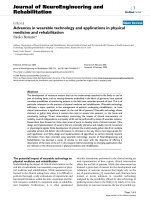
forces are large, the nanostructures will deform or clump together. For example, the
nanorods fabricated by the PVD technique in our lab deformed severely upon water
exposure as shown in figure 2. Such a deformation in these 3D skyscraper nanostructures
will reduce the total surface area, thus posing a serious problem for their application in
functional biosensor devices because a majority of biosensors will have to be exposed
aqueous environments. Therefore, to be useful as a component in a biosensor, these
nanostructures need to have sufficient mechanical strength to overcome the capillary forces.
New Perspectives in Biosensors Technology and Applications
272
Fig. 2. Deformed 3D skyscraper silicon nanorod structures upon water exposure: (A) a top
view and (B) a side view.
3. Fabrication processes for robust 3D skyscraper nanostructures
To overcome this problem, robust 3D skyscraper structures are necessary. One solution is to
use an aqueous based fabrication technique instead of a vapor based method. We have
developed a template based electrodeposition technique to fabricate 3D skyscraper
nanostructures (Anandan et al., 2006, 2007). In this aqueous based fabrication method,
porous anodic alumina (PAA) discs are used as templates to guide the electrodeposition of
conducting materials through the pores of the PAA templates in a three-electrode
electrochemical cell, in which a gold-coated PAA disc is used as working electrode, a
platinum (Pt) wire gauze as counter electrode and an Ag/AgCl electrode as reference
electrode. In this fabrication process, a thin gold layer about 150 nm thick is first sputter-
coated onto one side of a PAA disc to provide a conductive coating. Then a thicker gold
layer (~3 µm) is electrodeposited on top of the sputtered gold film to form a strong
supporting base in Orotemp24 gold plating solution (Technic Inc, Cranston, RI) at a
deposition current of 5 mA/cm
2
for about two minutes. The supporting base is then masked
with Miccrostop solution (Pyramid plastics Inc., Hope, Arkansas). After that, gold
nanopillars are electrodeposited through the open pores of the PAA disc from the uncoated
side at a deposition current of 5 mA/cm
2
at 65 °C in the same plating solution. The
deposition time can be varied for achieving nanopillars of different heights. After nanopillar
deposition, the PAA disc is dissolved in 2.0 M NaOH, resulting in a thin sheet structure with
a 2D array of vertical gold nanopillars standing on a gold film.
To assess the mechanical robustness of these nanopillars, a water droplet test can be
performed (Fan et al., 2004). To do that, a water droplet is placed on a 3D nanopillar
structure and is allowed to dry for several hours. After that, the morphology of the
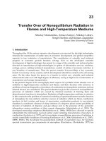
nanopillars is examined under scanning electron microscopy (SEM). Figure 3 shows two
SEM images of 3D gold nanopillar structures. These nanopillars have a diameter of about
150 nm and a height approximately 4.5 μm. Clearly, the nanopillars exhibited slight
clumping or bunching at their top ends. This bunching phenomenon, however, is different
from the collapsing type of deformation shown in figure 2. Although this bunching
deformation is due to the same capillary interaction between the nanopillars and water
during the removal of PAA templates, the morphology of the 3D nanopillar structures after
water exposure (Fig. 3A) is found to be almost identical to that before water exposure
Design and Fabrication of 3D Skyscraper Nanostructures and Their Applications in Biosensors
273
(Fig. 3B). This fact indicates that exposing these nanopillar structures to water did not cause
any further deformation, suggesting that the nanopillars fabricated by this aqueous based
electrodeposition method are mechanically strong.
Fig. 3. 3D gold nanopillar (aspect ratio=30) structures developed using an aqueous based
electrodeposition method: (A) as deposited, and (B) after water exposure.
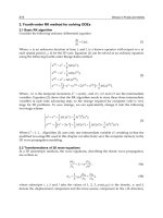
The type of deformation shown in figure 3 is believed related to the high aspect ratio of
these nanopillars. With an aspect ratio of 30, the bending resistance of the nanopillars will
certainly be reduced. When silver nanopillar structures with an aspect ratio of 10 (Fig. 4A &
4B) and gold nanopillar structures with an aspect ratio of 5 (Fig. 4C & 4D) are tested, both
cases show no bunching or clumping deformation in the nanopillars after water exposure
(Fig. 4B & 4D) as compared with before water exposure (Fig. 4A & 4C). These results
indicate that the nanopillar array structures developed using an aqueous electrodeposition
method do possess sufficient mechanical robustness to resist the capillary interaction forces.
Since the 3D skyscraper nanopillar presented above are made of different materials and with
different diameters, it raises a question: will such differences affect the resistance of these
nanopillars to capillary interaction? By considering a standing nanopillar as a cantilever beam
with a point load (
P , representing the net equivalent capillary force) acting on it, the
deflection of the nanopillar (
δ
) can be expressed as
3
3PL EI
δ
= (Beer et al., 2002), where E is
Young’s modulus of the material, L is the height of the nanopillar and I is the second moment
of inertia (
4
64ID
π
=⋅ , D is the diameter of the nanopillar). Obviously, the diameter of the
nanopillar will affect the bending rigidity. However, according to Kralchevsky et al. (2000) the
capillary force generated at the nanopillar is proportional to the diameter of nanopillar as
(,, )
i
PK d D
γ
ϕ
=⋅, where (,, )
i
Kd
γ
φ
is a function of physical conditions such as the surface
tension (
γ
), contact angle (
φ
) as well as the internanopillar distance (
i
d
). Thus, the deflection
of the nanopillar upon capillary interaction is proportional to the aspect ratio to the third
power and is inversely related to the Young’s modulus as
3
()LD E
δ
∝ . Therefore, aside from
these physical conditions, the aspect ratio of the nanopillars and their mechanical properties
are important factors influencing the resistance of these nanopillars to capillary interaction.
Since the values of the Young’s modulus of amorphous silicon, gold and silver are very close:
80 GPa for silicon (Freund et al., 2003), 78 GPa for gold and 83 GPa for silver (Gardner et al.,
2002), only the physical conditions (the surface tension, contact angle and internanopillar
distance) and the aspect ratio will have dominating effects on the resistance of these
nanopillars to capillary interaction.
New Perspectives in Biosensors Technology and Applications
274
A
B
C
D
Fig. 4. 3D silver nanopillar (aspect ratio = 10) structures before (A) and after (B) water exposure
and 3D gold nanopillar (aspect ratio = 5) structures before (C) and after (D) water exposure.
A
network of connected micro dots
A pair of interdigitated electrodes
Zoom-in view
Zoom-in view
Zoom-in view
Close-up top view
Close-up
side view
Fig. 5. SEM images showing a micro scale structure (a network of connected microdots) and
a device (a pair of interdigitated electrodes) fabricated out of 3D skyscraper nanopillar
structures.
Design and Fabrication of 3D Skyscraper Nanostructures and Their Applications in Biosensors
275
Although robust, these 3D skyscraper nanostructures are formed on free-standing thin
films. One drawback of such structures is that it is difficult to turn them into devices
through further structural processing. To be able to process these 3D structures through
conventional lithographical steps, it is ideal to have these 3D nanostructures formed on a
supporting wafer substrate. To meet this need, we have developed a novel process to
fabricate 3D skyscraper nanostructures on glass or wafer substrates (Zhang et al., 2008). In
this process, multiple layers of metallic films (e.g., 5 nm Titanium layer, 10 nm Gold layer
and 10 μm Alumium layer) are first deposited onto the substrate. Then the top aluminum
layer is anodized to form a porous Alumina template. After that, gold nanopillars are
electrodeposited into the pores of the template. Finally, the porous alumia template is
removed. With such nano structures formed on this surpporting substrate, we then pattern
them into micro devices via conventional photolithographic processes. Figure 5 shows some
examples of such integrated micro and nano structures on glass substrates: a network of
connected micro dots and a pair of interdigitated electrodes fabricated out of 3D skyscraper
nanopillar structures.
4. Electrochemical characterization of 3D skyscraper nanostructures
4.1 Bare surfaces
To characterize the 3D skyscraper nanostructures with bare surfaces, cyclic voltammetry
(CV) analysis can be performed. To do that, the 3D nanostructures are used as working
electrode in a three-electrode electrochemical cell. Figure 6 shows the CV curves for three
nanopillar structures and a flat control structure measured in blank solution containing 0.3
M sulphuric acid as a supporting electrolyte. The inset in figure 6 shows the SEM images of
a side-view of the three specimens. From these SEM images, it is estimated that the
nanopillars in specimens A, B and C have a diameter of about 150.0 nm and a height
approximately 1.0 µm, 2.5 µm and 6.0 µm, respectively.
Potential (mV vs Ag/AgCl)
-0.5 0.0 0.5 1.0 1.5
C
urrent
(
μA
)
-2500
-2000
-1500
-1000
-500
0
500
1000
Flat electrode (RF=1)
Nano A (RF=20.0)
Nano B (RF=38.8)
Nano C (RF=63.4)
ABC
Potential (V, Ag/AgCl)
Current
(μA)
Fig. 6. CV curves for three 3D nanopillar structures and a flat structure with bare surfaces
obtained in blank solution containing 0.3 M sulphuric acid as a supporting electrolyte. The
inset shows the SEM images of a side-view of the three specimens.
New Perspectives in Biosensors Technology and Applications
276
All these CV curves show an Au-oxide reduction peak at around 0.85 V, as expected. To
quantify the difference in the height of the nanopillars in these 3D skyscraper structures, a
roughness factor is determined as the area under the reduction peak of a nanopillar
electrode divided by that of the flat electrode. The roughness factor (RF) for specimens A, B
and C is found to be 20.0, 38.8 and 63.4, respectively.
When a redox couple, [Fe(CN)
6
]
4-
/[Fe(CN)
6
]
3-
, is used along with a supporting electrolyte,
more structural characteristics can be revealed from the CV curves. Figure 7 shows the CV
curves for a 3D and a flat gold structures measured in solution containing 0.5 M Na
2
SO
4
as a
supporting electrolyte and 4 mM K
4
Fe(CN)
6
as a redox probe. The CV curves show that the
redox peak current increases with increasing scan rate. Furthermore, the peak currents for
the 3D nanopillar structures are much higher than those for the flat one. Here each CV curve
represents 10 cycles of repeated measurements, suggesting that the 3D nanopillar structures
are very stable with no further deformation or change in morphology during the
electrochemical processes. If these nanopillars are not strong enough to overcome the
capillary forces in such an aqueous environment, they will deform during the
electrochemical processes, which will subsequently lead to decreased active surface area and
hence decreased current output.
Potential (V) vs Ag/AgCl
-0.6 -0.4 -0.2 0.0 0.2 0.4 0.6
C
urrent
(
µA
)
-300
-200
-100
0
100
200
300
400
scan rate 50mV/s
scan rate 100mV/s
scan rate 150mV/s
scan rate 200mV/s
Potential (V) vs Ag/AgCl
-0.6 -0.4 -0.2 0.0 0.2 0.4 0.6
Current (µA)
-400
-200
0
200
400
600
800
scan rate 50mV/s
scan rate 100mV/s
scan rate 150mV/s
scan rate 200mV/s
A
B
Scan Rate: 50 mV/s
Scan Rate:100 mV/s
Scan R ate: 150 m V/s
Scan R ate: 200 m V/s
Scan Rate: 50 mV/s
Scan Rate:100 mV/s
Scan Rate: 150 m V/s
Scan Rate: 200 m V/s
Potential (V, Ag/AgCl)
Potential (V, Ag/AgCl)
Current (μA)
Current (μA)
Fig. 7. CV curves for a gold flat (A) and 3D nanopillar (B) structures with bare surfaces
obtained in solution containing 0.5 M Na
2
SO
4
as a supporting electrolyte and 4mM K
4
Fe(CN)
6
as a redox probe.
From these CV curves, a peak separation ΔE
p
= 70 mV is found for the 3D nanopillar
structure, which is much closer to an ideal Nernstian behavior (ΔE
p
= 59 mV) as compared
with that for the flat structure (ΔE
p
= 110 mV), indicating that electron transfer at the surface
of the 3D nanopillar structures is significantly enhanced.
4.2 SAM treated surfaces
As discussed earlier, most of these 3D skyscraper nanostructures are made of inorganic
materials, thus for applications as electrodes in biosensors they have to be functionalized for
biological recognition purposes. Since most biosensitive molecules cannot be immobilized
directly onto the surface of these inorganic materials, anchoring molecules such as self
assembled monolayer (SAM) molecules are necessary. We have evaluated the formation of
two SAM molecules, i.e., (1) 3-mercaptopropionic acid or MPA: HS-(CH
2
)
2
-COOH and (2)
Design and Fabrication of 3D Skyscraper Nanostructures and Their Applications in Biosensors
277
11-mercaptoundecanoic acid or MUA: HS-(CH
2
)
10
-COOH at the surface of these 3D
nanopillar structures (Anandan et al., 2009). To treat the 3D nanopillar structures with the
SAM molecules, the structures are immersed in ethanol solution containing 10 mM of either
the MPA or MUA molecules for 24 hours. SAM formation on these 3D structures is
characterized by the CV and electrochemical impedance spectroscopy (EIS) techniques. The
CV measurements are performed by scanning the potential from -0.2 V to 0.6 V at a scan rate
of 100 mV/s and the EIS measurements are performed in a frequency range from 0.1 Hz to
100 KHz at a potential of 10 mV in 0.1 M phosphate buffered solution (PBS, pH7) containing
2 mM Fe(CN)
6
3-/4-
(ferri:ferro=1:1) mixture as a redox probe.
For assessing the percentage of defects in the SAM molecules, the voltammetric reduction
peak associated with the uncovered area (i.e., the exposed gold oxide) in the SAM treated
3D structures is evaluated. The ratio of the uncovered area of a SAM treated 3D structure to
that of a bare 3D structure is calculated and the percentage of defects in the SAM molecules
is determined. To quantify the surface coverage (Г) of the SAM molecules, the method
reported in the literature (Walczak et al., 1991; Sawaguchi et al., 2001; Ding et al., 2005) is
used to evaluate the voltammetric reduction peak associated with SAM desorption. From
the reduction peak, the amount of charge is determined by first integrating the reduction
current under the peak over time and then offsetting the value by that of a bare 3D
electrode. With the formula Г=Q/nFA (Walczak et al., 1991), in which Q is the amount of
charge, n (=1) is the number of electrons involved in the reaction, F (=96485 C/mol) is the
Faraday constant and A (=0.04 cm
2
) is the electroactive surface area, the surface coverage of
SAM molecules is determined.
Potential (V vs. Ag/AgCl)
-0.4 -0.2 0.0 0.2 0.4 0.6 0.8
Current (
μ
A)
-150
-100
-50
0
50
100
150
200
Bare
MPA
MUA
A
|Z'| (kΩ)
0 10203040506070
|Z''| (kΩ)
0
20
40
60
80
MPA
MUA
|Z'| (kΩ)
01234567
|Z''| (k
Ω
)
0.0
0.5
1.0
1.5
2.0
2.5
3.0
3.5
Bare
MPA
B
Potential (V, Ag/AgCl)
|Z’| (kΩ)
|Z”| (kΩ)
-0.4 -0.2 0.0 0.2 0.4 0.6 0.8
200
150
100
50
0
-50
-100
-150
Current (μA)
Fig. 8. (A) CV curves for a bare, MPA and MUA treated surfaces obtained in solution
containing H
2
SO
4
as a supporting electrolyte and [Fe(CN)
6
]
4-
/[Fe(CN)
6
]
3-
as a redox probe at
a scan rate of 100 mV/s. (B) The corresponding Nyquist plots from the EIS measurements
with a close-up view of the low impedance range given in the inset.
In figure 8A the CV curves obtained for a bare, MPA and MUA treated 3D structures
evaluated in the presence of the redox couple [Fe(CN)
6
]
4-
/[Fe(CN)
6
]
3-
are shown. In
comparison between the bare and SAM treated structures, the bare one exhibits much
higher redox peak currents. Between the two SAM treated structures, the MUA treated one
exhibits lower redox peak currents than the MPA treated one, suggesting a higher degree of
blockage for electron transfer resulting from the MUA molecules than from the MPA
New Perspectives in Biosensors Technology and Applications
278
molecules. For both the bare and the MPA treated 3D structures the CV curves show a
reversible redox event occurring at the surface with the electron transfer limited by
diffusional mass transport. By contrast, the CV curves for the MUA treated structure
exhibits highly irreversible redox behavior, confirming a high degree of blockage at the
surface for electron transfer. Taken together, the above results indicate that both the MUA
and MPA molecules form SAM structures covering the surface of the 3D nanopillar
structures and that there are more MUA molecules than MPA molecules blocking the
pathways for electron transfer across the electrode-electrolyte interface, owing possibly to
the longer chain length of the MUA molecules forming more lateral molecular bonds.
Figure 8B shows the corresponding impedance spectra (Nyquist plots) for these 3D
structures. The two SAM treated structures show semicircular Nyquist plots whereas the
bare one exhibits a straight line plot (see the lower inset plot in Fig. 8B). Since a semicircular
feature is indicative of blockage for electron transfer across the electrode/electrolyte
interface, this result confirms the formation of SAM molecules at the surfaces. Moreover, the
MUA treated structure exhibits a larger semicircle than the MPA treated one, suggesting a
high degree of SAM coverage for the MUA than for the MPA molecules. By using a Randles
equivalent circuit to fit the obtained semicircular Nyquist plots, the resistance value for
electron transfer (R
et
) can be resolved. In this case, the R
et
value obtained for the MUA
treated structure is 27 times higher than that for the MPA treated structure. This result
confirms that the MUA molecules indeed post a higher electron transfer resistance at the
electrode surface than the MPA molecules.
The CV curves obtained from the Au-oxide reduction experiments (figure 9A) exhibit an
Au-oxide reduction peak at around 0.78 V, indicating that all these 3D electrodes possess a
certain amount of defects on the SAM treated surfaces. By the ratio of the area under the
reduction peak (by integrating the CV curve under the peak) of the SAM treated 3D
structure to that of the bare 3D structure, the percentage of defects is found to be
approximately 87.3% and 37.8% for the MPA and MUA SAMs, respectively. These values
are high when compared with flat structures: 52% for the MPA and 0% for the MUA SAMs
(Campuzano et al., 2002).
Potential (V vs. Ag/AgCl)
-0.50.00.51.01.5
C
urren
t
(
μ
A)
-1200
-1000
-800
-600
-400
-200
0
200
400
600
800
1000
Bare
MPA
MUA
A
Voltage (V vs. Ag/AgCl)
-1.8 -1.6 -1.4 -1.2 -1.0 -0.8 -0.6 -0.4 -0.2 0.0
Current (
μ
A)
-800
-600
-400
-200
0
200
Bare
MPA
MUA
SAM desorption peaks
B
Potential (V, Ag/AgCl)
Potential (V, Ag/AgCl)
Current (μA)
Current (μA)
Fig. 9. (A) CV curves for a bare, MPA and MUA treated 3D structures obtained in quantifying
the percentage of defects in SAM molecules in blank solution containing 0.1 M H
2
SO
4
as a
supporting electrolyte. (B) CV curves for the same structures obtained in evaluating SAM
desorption in blank solution containing 0.1M NaOH as a supporting electrolyte.
Design and Fabrication of 3D Skyscraper Nanostructures and Their Applications in Biosensors
279
Figure 9B shows the CV curves obtained for evaluating the voltammetric reduction peak
associated with desorption of the MPA and MUA molecules. In the CV curves, two peak
currents are visible for both the MPA and MUA treated 3D structures. The peak current at
around -0.82 V for the MPA and around -1.03 V for the MUA are due to the cleavage of the
gold-sulfur bond, according to the literature that a peak desorption current between -0.6 to -
0.9 V is reported for short alkanethiols (n=2 to 6) and between -1.0 to -1.2 V for long
alkanethiols (n=11 to 18) (Widrig et al., 1991; Imabayashi et al., 1997; Sawaguchi et al., 2001;
Ding et al., 2005). Based on these desorption peak currents, the desorption charge is
determined by integrating the reduction peak from -0.8 V to -0.9 V for the MPA treated
structure and from -1.0 V to -1.2 V for the MUA treated structure. The surface coverage
values are found to be 1.38×10
-8
mol/cm
2
and 2.37×10
-8
mol/cm
2
for the MPA and MUA
treated electrodes respectively. Comparing with the reported values for the surface coverage
for the MPA (5.12×10
-10
mol/cm
2
) and the MUA (8.30×10
-10
mol/cm
2
) on flat surfaces
(Campuzano et al., 2002), the values for the 3D nanopillar structures are roughly 27 and 28
times higher. This increase can be attributed to the increase in the electroactive surface area
in the 3D electrodes.
4.3 Functionalized surfaces using SAM and avidin
Since these SAM molecules only serve as an anchoring layer, functional molecules are still
needed to make these 3D skyscraper nanostructures functionally sensitive to analyte targets.
Many biological couples such as antibody-antigen, protein-ligand, protein-aptamer, paired-
nucleotides and avidin-biotin can be used for this purpose. Here we will discuss a case
using the avidin-biotin couple as the biosensitive element for a biosensor. In using the
avidin-biotin couple, one species, often avidin, has to be immobilized onto the active surface
of the biosensor, and the other is usually tethered to a target molecule. As a demonstration,
we will immobilize avidin and use biotin as the target.
O
HO
S
Au
O
O
S
Au
O
O
N
EDC/NHS
H
2
N-AVIDIN
O
HN
S
Au
AVIDINE
Au
MUA
O
HN
S
Au
BIOTIN
BIOTIN
Au
(gold nanorods)
O
HO
S
Au
O
O
S
Au
O
O
N
EDC/NHS
H
2
N-AVIDIN
O
HN
S
Au
AVIDINE
Au
MUA
O
HN
S
Au
BIOTIN
BIOTIN
Au
(gold nanorods)
Au
(gold nanorods)
Au
(gold nanorods)
3D Skyscraper
Nanostructures
AVIDIN
Fig. 10. Schematic illustration of a sequential procedure used to modify the surface of a 3D
gold nanopillar structure.
New Perspectives in Biosensors Technology and Applications
280
A SAM of anchoring MUA molecules is first formed at the surface of a 3D nanopillar
structure. The MUA is then activated (i.e., turning the COOH groups into reactive
N-hydroxysuccinimice esters) by immersing the structure in PBS containing 30 mM
1-3-Dimethyl-amino-propyl-3-ethyl-carbodiimide hydrochloride and 15 mM N-hydroxy-
succin-imide for 3 hours at 25ºC. The 3D structure is then functionalized with avidin in PBS
solution containing 300 μL of avidin at 200 μg/mL for 2 hours at 25ºC. Figure 10 shows a
schematic illustration of the stepwise procedures for the surface modification.
Figure 11A shows the CV measurements during the stepwise surface modification using
MUA, avidin and biotin. Clearly, a bare 3D structure exhibits a peak-shaped CV curve,
indicating a diffusion-controlled electrode process. Moreover, the CV curve has a peak-to-
peak separation measured at ΔE
p
= 59.8 mV, which is very close to an ideal Nernstian one-
electron reaction having ΔE
p
= 59 mV (Bard et al., 2001). This fact suggests a highly efficient
electron transfer mechanism across the electrode/electrolyte interface of the 3D nanopillar
structure.
After the MUA layer is adsorbed to the electrode surface, the peak-shaped CV curve exhibits
much reduced peak currents and increased peak-to-peak separation, suggesting blockage
for electron transfer due to MUA adsorption. With more layers of molecular adsorption (i.e.,
avidin and biotin), the CV curve shows no obvious redox peaks. Instead, it looks more like a
sigmoid having significant hysteresis between the forward and backward scans. This
behavior implies that the electrons passing across the electrode/electrolyte interface are
fulfilling two duties: to facilitate redox reaction and to charge the electrical double layer.
Also, a lack of peak currents in these CV curves suggests that the adsorption of molecules to
the surface has significantly lowered the electron transfer rate such that the electrode
process is no longer controlled by a diffusion process as in the case of a bare electrode.
Instead, it is now a kinetics-controlled process, meaning that it is limited by the rate of
electron transfer.
Z
re
(kΩ )
0 5 10 15 20 25 30
Z
im
(kΩ)
-20
-15
-10
-5
0
(a) B are
(b) MUA
(c) M U A + Avidin
(d) MU A + Avidin + Biotin
(a)
(b)
(c)
(d)
0.2 0.4 0.6 0.8
-1.0
-0.8
-0.6
-0.4
-0.2
0.0
(a)
B
Potential vs. Ag/A gCl (V )
-0.2 0.0 0.2 0.4 0.6 0.8
Current (μA)
-30
-20
-10
0
10
20
30
(a) Bare
(b) MUA
(c) M UA + Avidin
(d) M U A + A vidin + B io tin
(a)
(b)
(c)
(d)
A
30
20
10
0
-10
-20
-30
-0.2 0.0 0.2 0.4 0.6 0.8
0 5 10 15 20 25 30
|Z’| (kΩ)
-20
-15
-10
-5
0
|Z”| (kΩ)
Potential (V, Ag/AgCl)
Current (μA)
(a) Bare
(b) MUA
(c) MUA + Avidin
(d) MUA + Avidin+ Biotin
(a) Bare
(b) MUA
(c) MUA + Avidin
(d) MUA + Avidin + Biotin
Fig. 11. (A) CV curves for examining the electrode/electrolyte interface during stepwise
surface modification. (B) The corresponding Nyquist plots with a close view of the trace (a).
As shown in figure 11A, the peak current (or the limiting current) of these CV curves
decreases as more layers of molecules are adsorbed to the surface. This is because the
increase in the thickness of the adsorbed molecular layer at the surface has caused further
reduction in electron transfer, thus slowing down the redox activity of [Fe(CN)
6
]
4-
/[Fe(CN)
6
]
3-
.
Design and Fabrication of 3D Skyscraper Nanostructures and Their Applications in Biosensors
281
The observed sequential change in the CV curve corresponds very well with the stepwise
adsorption of MUA, avidin and biotin at the surface.
From the EIS measurements shown in figure 11B, it is seen that the Nyquist plot for the bare
3D structure (see inset) is nearly a straight line with its slope close to one. This fact confirms
a diffusion-controlled electrode process occurring at the surface of the bare 3D structure. For
the other cases, semicircular Nyquist impedance spectra are observed. The diameter of these
Nyquist semicircles increases as the sequential adsorption of MUA, avidin and biotin
proceeds at the surface. This fact indicates that the resistance to electron transfer at the
electrode/electrolyte interface increases as more layers of molecules are added to the
surface. Moreover, these Nyquist plots do not possess a linear part at low frequency,
confirming that after the adsorption of various molecules the electrode process is no longer
a diffusion-controlled process but a kinetics-controlled one.
4.4 Functionalized surfaces using PPy and GOx
In many biosensors, the functionalization of electrodes made of 3D skyscraper structures is
often aimed at a specific target. In a glucose biosensor, for example, its electrode should be
reactive to glucose. Very often, glucose specific enzyme – glucose oxidase (GOx) – is
immobilized onto the surface of the electrode with the use of anchoring molecules such as
SAM molecules. One drawback of using SAM molecules is that they always get in the way
of electron transfer across the electrode/electrolyte interface as demonstrated in section 4.3
(see figure 11), thus affecting the detection performances. In contrast, physical entrapment of
GOx in a porous polymer film near the electrode surface offers an attractive alternative.
Conducting polymer like polypyrrole (PPy) can be electro- polymerized and deposited onto
electrode surfaces to form a porous film, providing pores large enough for efficient electron
transfer. Thus by mixing GOx in pyrrole solution, a porous polymeric film with GOx
entrapped inside can be formed at the electrode surface via electrodeposition.
Fig. 12. (A) CV curves for five 3D nanopillar structures with different roughness factors
obtained in blank solution containing 0.5 M H
2
SO
4
as a supporting electrolyte. (B) Variation
of amperometric steady-state current with roughness factor in response to glucose for the
five 3D electrodes. Note N=3 for each data point.
We have applied the functionalization procedure using PPy and GOx to 3D skyscraper
nanopillar structures and investigated the effect of various parameters, such as the height of
New Perspectives in Biosensors Technology and Applications
282
nanopillars, the electrodeposition current and the total charge passed, on the performance of
the 3D electrodes in glucose detection. Figure 12A shows the CV curves obtained in blank
solution containing 0.5 M H
2
SO
4
for five 3D structures with different nanopillar heights. All
the CV curves exhibit an Au-oxide reduction peak at around 0.85 V. From these reduction
peaks, the roughness factor for the five 3D structures is found ranging from 13.5, 23.0, 35.0
and 57.0 to 80.0.
Figure 12B shows the amperometric steady-state current in response to glucose at a fixed
concentration of 4 mM for the five 3D structures functionalized at two deposition currents
(100 µA/cm
2
and 191 µA/cm
2
) with the total charge set at 150 mC/cm
2
. Clearly, the steady-
state current increases as the roughness factor increases and it appears to saturate when the
roughness factor goes beyond 57. The same phenomenon is seen for both current cases. This
current-saturation behavior at a higher roughness factor is believed due to the difficulty
encountered by glucose in diffusing down to the sides and roots of the nanopillars for
oxidation as the height of the nanopillars reaches a certain level. This result is consistent
with our previous observation (Anandan et al., 2007), and it may suggest that for glucose
detection using the present method it is not necessarily beneficial to have 3D structures with
nanopillars that are too tall. Figure 12B also shows that the steady-state current for the
structures functionalized under a lower deposition current is higher than that under a
higher deposition current, owing to a more uniform thickness for the PPy/GOx film formed
under a lower deposition current.
Depostion Current (μA/cm
2
)
0 100 200 300 400
Steady-State Current (
μ
A/cm
2
)
100
120
140
160
180
200
Total Charge = 150 mC/cm
2
Total Charge = 75 mC/cm
2
Fig. 13. Variation of the amperometric steady-state current with deposition current obtained
under two different total charges. Note N=3 for each data point.
Figure 13 shows the variation of stead-state current with deposition current for 3D
structures with a roughness factor around 60. At a total charge of 150 mC/cm
2
the steady-
state current increases as the deposition current decreases but with no obvious peak current
performance within the range of the applied deposition currents (i.e., from 50 to 573
µA/cm
2
). When the deposition current is lowered below 50 µA/cm
2
(achieved at a reduced
total charge of 75 mC/cm
2
) it became obvious that the steady-state current reached at the
Design and Fabrication of 3D Skyscraper Nanostructures and Their Applications in Biosensors
283
deposition current of 50 µA/cm
2
is a peak value. From the overlap region of the two curves
it is seen that these two curves are not only very close to each (the one under a lower charge
density is slightly lower than the one under a higher charge density, as expected) but also
following the same varying trend. Based on these results, the deposition current of 50
µA/cm
2
is deemed as an optimal value, which is quite different from that obtained for flat
electrodes (382 µA/cm
2
).
This difference is attributed to the presence of the nanopillars. Because of these closely
packed skyscraper nanopillars, the mass transport of the electroactive species (including
pyrrole during electrodeposition and glucose during detection) to and from the functionalized
surface will be different from the case without nanopillars. This is evident from the SEM
images. Under a lower deposition current of 50 µA/cm
2
all nanopillars are covered with a
thin uniform layer of PPy/GOx (see Fig.14A). However, under a higher deposition current
of 573 µA/cm
2
, the space between nanopillars close to the tips is all clogged up by the
PPy/GOx (Fig.14B). This thick film formed under high deposition currents will surely pose
a diffusion barrier for glucose, thus leading to low current responses (Fortier et al., 1990).
Therefore, in the presence of closely packed skyscraper nanopillars, a much lower
deposition current (e.g., 50 µA/cm
2
instead of 382 µA/cm
2
) is necessary for forming a
uniform functionalization layer at the surface of these 3D nanopillar structures.
A B
Fig. 14. SEM images of 3D nanopillar structures functionalized with PPy/GOx through an
electrodeposition process when the total charge is controlled at 150 mC/cm
2
under a
deposition current of 50 µA/cm
2
(A) and 573 µA/cm
2
(B).
Figure 15A shows the variation of steady-state current with total charge measured in
response to glucose for the 3D nanopillar structures (with a roughness factor around 60)
functionalized at a fixed deposition current of 50 µA/cm
2
. As the total charge increases from
50 to 600 mC/cm
2
, the steady-state current increases a little bit in the beginning and then
decreases after reaching a peak value at 150 mC/cm
2
. Figure 15B shows the steady-state
currents for the 3D nanopillar structures measured in response to ascorbic acid. Ascorbic
acid, uric acid and acetaminophen are the common electroactive species coexisting in blood,
and they tend to affect the accuracy of a glucose sensor (Cho et al., 1996). Thus for a better
performance, a glucose sensor should have negligible responses to these nonspecific species.
In general, ascorbic acid is considered as a representing endogenous interfering agent
(Moatti et al., 1992), thus for this reason we choose ascorbic acid as a representative
interfering species. These results show that the interference also reaches a peak value at a
New Perspectives in Biosensors Technology and Applications
284
total charge of 150 mC/cm
2
. But the current value in response to ascorbic acid is much lower
(14.3 µA/cm
2
) than that to glucose (138.3 µA/cm
2
). With a signal-to-noise ratio of about 9.7,
the specificity of the functionalized 3D nanopillar structures to glucose is considered to be
reasonably good.
Total Charge (mC/cm
2
)
0 100 200 300 400 500 600
Steady-State Current (
μ
A/cm
2
)
0
20
40
60
80
100
120
140
160
Total Charge (mC/cm
2
)
100 200 300 400 500 600
Steady-State Current (μA/cm
2
)
6
8
10
12
14
16
18
20
A
B
100 200 300 400 500 600
0 100 200 300 400 500 600
Total Charge (mC/cm
2
)
Total Charge (mC/cm
2
)
160
140
120
100
80
40
20
0
Steady-State Current (mA/cm
2
)
20
18
16
14
12
10
8
6
Steady-State Current (mA/cm
2
)
Fig. 15. Variation of amperometric steady-state current with total charge obtained for the
functionalized 3D nanopillar structures (under a deposition current of 50 µA/cm
2
) in
response to glucose (A) and to ascorbic acid (B). Note N=3 for each data point.
Based on these results we believe that an electro-process with a deposition current of 50
µA/cm
2
and a total charge of 150mC/cm
2
will provide an optimal condition for
functionalizing the 3D nanopillar structures using PPy/GOx. These electro-processing
parameters are quite different from those obtained for the flat electrodes (Uang et al., 2002),
and it can be attributed to the added surface area provided by the cylindrical walls of the
nanopillars as well as the added difficulty for the active species in reaching the tiny space
between these nanopillars (Anandan et al., 2007).
5. Application of 3D skyscraper nanostructures as electrodes in biosensors
Now let us compare the two functionalization methods by examining the detection
sensitivity when these functionalized 3D nanopillar structures are used as electrodes for
glucose detection. In the first case, the 3D nanopillar structures functionalized with SAM
and GOx (in which GOx is tethered to the SAM) are used as electrodes, and in the second
case the 3D nanopillar structures functionalized with PPy and GOx (in which GOx is
entrapped in a porous film of PPy) are used as electrodes. In both cases, the amperometric
steady-state current responses of these functionalized electrodes are measured in response
to glucose at different concentrations. With the amperometric measurements, the
relationship between the steady-state current and glucose concentration is calibrated in each
case. From the calibration curves the detection sensitivity of the 3D nanopillar electrodes
functionalized with two different methods is evaluated and compared.
5.1 Electrode reactions in Gox catalyzed glucose detection
For GOx catalyzed glucose detection, glucose first reacts with GOx to form gluconic acid
and reduced-GOx. The reduced-GOx will then be converted back to its original form by
Design and Fabrication of 3D Skyscraper Nanostructures and Their Applications in Biosensors
285
reacting with p-benzoquinone (BQ), a mediator having better solubility than most other
popular mediators (Cooper et al., 1993). In a cascade of electrode reactions, the mediator gets
reduced and then converted back to its original state at the electrode surface by giving away
electrons. Figure 16 shows a cascade of events occurring in a mediator based glucose
detection scheme.
β
-Glucose
Gluconic acid
Gox (ox)
Gox
(
red
)
BQ (red)
BQ
(
ox
)
e
-
Fig. 16. A cascade of events in a mediator-based glucose detection scheme.
5.2 Glucose detection using electrodes functionalized with SAM and GOx
By using 3D nanopillar structures treated first with a SAM of MPA molecules followed by
GOx as electrodes, amperometric measurements are made in PBS containing 3mM p-
benzoquinone and certain amount of glucose at a constant electrode potential of 0.35 V (vs.
Ag/AgCl). During amperometric experiment, the solution is stirred constantly for ensuring
instant equilibrium for mass transport. During each test run, the background current is
allowed to stabilize before a drop of glucose is added to the solution. After the
amperometric current response reaches a steady-state, another drop of glucose is added and
the corresponding current response is measured until a new steady state is reached. In this
experiment each incremental drop of glucose is controlled to cause an equivalent increase in
glucose concentration of approximately 2.5 mM.
Concentration (mM)
0 2 4 6 8 10 12 14 16
Current (
μ
A
)
0
1
2
3
4
5
6
Flat Electrode
Nano A
Nano B
Nano C
R
2
=0.998
R
2
=0.996
R
2
=0.996
R
2
=0.990
B
Time ( seconds )
800 1000 1200 1400 1600
Current (
μ
A)
0
2
4
6
8
10
A
Nano A
Nano B
Nano C
Flat Electrode
2.5mM
5mM
A
B
Fig. 17. (A) Amperometric current responses obtained for 3D electrodes functionalized with
SAM and GOx when incremental drops of glucose are added to the solution. (B) Calibration
curves along with linear-regression analyses for the relationship between the steady-state
current and glucose concentration (from 2.5mM to 15mM).
Figure 17A shows the amperometric current responses for three 3D nanopillar electrodes
and a flat control electrode functionalized with MPA SAM and GOx. These three 3D
electrodes have different surface roughness factors as characterized in figure 6. All three
electrodes exhibit a higher current response than the flat control case at each glucose level.
Figure 17B shows the variations of steady-state current with glucose concentration (from