Progress in Biomass and Bioenergy Production Part 11 pot
Bạn đang xem bản rút gọn của tài liệu. Xem và tải ngay bản đầy đủ của tài liệu tại đây (1.6 MB, 30 trang )
Recovery of Ammonia and Ketones from Biomass Wastes
289
0 4000 8000 12000
0
2
4
6
8
10
Adsorbent treated at 573 K
Adsorbent treated at 378 K
Adsorbent treated at 573 K
Calculated capacity
Calculated capacity
Adsorbent treated at 378 K
Ammonia concentration [ppm]
Adsorption amounts [mol-N/ kg-adsorbent]
Fig. 7. Adsorption isotherms of ammonium ions at room temperature on the adsorbent
obtained by treating MAP at 378 K and 573 K (Fumoto et al., 2009).
10 20 30 40 50 60
Intensity [-]
2
θ
[deg]
MAP
Adsorbent after adsorption of ammonium ions
Adsorbent before adsorption
MgNH
4
PO
4
·6H
2
O
MgNH
4
PO
4
·H
2
O
Fig. 8. XRD patterns of MAP and adsorbent treated at 378 K before and after the adsorption
of ammonium ions (Fumoto et al., 2009).
Progress in Biomass and Bioenergy Production
290
The amount of ammonium ions adsorbed on the adsorbent treated at 573 K was significantly
less than that of the adsorbent treated at 378 K, as shown in Fig. 7. Furthermore, the
experimental value was less than the calculated capacity in the case of the adsorbent treated
at 573 K. The fewer nanopores and smaller surface area of the adsorbent treated at 573 K
caused the lower adsorption of ammonium ions. The surface chemical properties of the
adsorbent may be different between the adsorbents treated at 378 K and 573 K.
Consequently, the adsorbent obtained by treating MAP at 378 K was more suitable for the
adsorption of ammonium ions.
2.4 Recovery of ammonium ions from animal wastes
The feasibility of recovering ammonia from biomass wastes was demonstrated using cow
urine. The urine was pretreated under a hydrothermal condition at 573 K for 1 h to convert
nitrogen compounds in the urine into ammonium ions. The pH was adjusted to 10.5 by
adding sodium hydroxide and the adsorbent treated at 378 K was added to the pretreated
urine at an adsorbent to urine weight ratio of 1:10. The nitrogen concentration was analyzed
after 1 h of stirring.
Recovery yield
[mol%-N]
Impurities deposition [mol/mol]
C/N S/N
Pretreated urine 56.9 0.103 0
Untreated urine 65.2 0.486 0.0196
Table 2. Nitrogen recovery yield and impurities deposited on the adsorbent from urine
solution (Fumoto et al., 2009).
Table 2 lists the nitrogen recovery yield and the impurities deposited on the adsorbent from
the urine; the results obtained using untreated urine are also shown. More than 50% of the
nitrogen was recovered from the urine using the adsorbent obtained by treating MAP at 378
K (Fumoto et al., 2009). The nitrogen concentration of the urine decreased to 2000 ppm after
the recovery experiment, and the remaining liquid wastes could be used as liquid fertilizer
because the liquid contained a low concentration of ammonia.
The nitrogen recovered from pretreated urine corresponded well with ammonium ions
because the carbon deposition on the adsorbent was small, as shown in Table 2. In contrast,
some carbon was deposited on the adsorbent from the untreated urine, indicating that most of
the nitrogen adsorbed on the adsorbent was urea. Furthermore, no sulfur was deposited on
the adsorbent from the pretreated urine, which contained sulfur. Therefore, large amounts of
ammonia were recovered from the biomass wastes using this method without impurities.
2.5 Desorption of ammonia from solids adsorbing ammonia
The recovery of ammonia by thermal treatment of the solids adsorbing gaseous ammonia
and aqueous ammonium ions was examined. The MAP structure was re-formed after the
adsorption of ammonium ions in liquid phase. Hence, the solid adsorbing gaseous ammonia
and MAP were loaded in the stainless column, followed by heating the column at a rate of 1
K/min in an argon stream. The solid, which was obtained by treating MAP at 378 K, was
used after the adsorption of gaseous ammonia. The ammonia and steam eliminated from the
solid and MAP was measured by Q-MS. The mass numbers were chosen as 15, 18, and 40 to
detect ammonia, steam, and argon, respectively.
Recovery of Ammonia and Ketones from Biomass Wastes
291
10
-12
10
-11
10
-10
10
-9
10
-8
10
-7
(b) MAP
(a) Solid adsorbing ammonia
Ar (m/e = 40)
NH
3
(m/e = 15)
H
2
O (m/e = 18)
Intensity [-]
300 320 340 360 378380 400
10
-13
10
-12
10
-11
10
-10
10
-9
10
-8
Temperature [K]
Cooling
378
Ar (m/e = 40)
H
2
O (m/e = 18)
NH
3
(m/e = 15)
Fig. 9. Gas fractions generated from the solid adsorbing gaseous ammonia and MAP.
Figure 9 describes the gas fractions eliminated from the solids adsorbing gaseous ammonia
and MAP. Ammonia was eliminated when these samples were heated. The solid adsorbing
gaseous ammonia released ammonia at a relatively lower temperature compared with the
MAP, suggesting the physical adsorption of gaseous ammonia. Steam may be desorbed
from moisture adsorbed on the surface of the solids and crystallization water of MAP. These
results indicate that ammonia could be recovered by thermal treatment of the solids after the
adsorption of gaseous ammonia and ammonium ions. Hence, the adsorbent derived from
MAP could be used repeatedly.
2.6 Stability of adsorbents for repeated use
The adsorbents derived from MAP are expected to be reused for the recycling process of
adsorption and desorption of ammonia. Sugiyama et al. (2005) reported that the removal of
ammonium ions in the second run was about 80% of that in the first run when an
ammonium removal experiment from aqueous ammonium ions was conducted using
adsorbent derived from MAP. The stability of the adsorbents was investigated for repeated
use in gaseous ammonium adsorption.
Progress in Biomass and Bioenergy Production
292
Figure 10 illustrates the change in amounts of adsorbed ammonia on the adsorbents when the
sequence of ammonia adsorption and desorption was repeated. After the adsorption of
gaseous ammonia at 313 K on the adsorbent obtained by treating MAP at 378 K, the adsorbent
was heated to 378 K to eliminate the ammonia, and it was used repeatedly for the adsorption
experiment. The amount of ammonia hardly changed in the adsorption/desorption sequence.
The pore structure of the adsorbent was almost maintained. Accordingly, this adsorbent is
useful for the recovery of ammonia with repeated sequences of adsorption and desorption.
01234
0
1
2
3
4
Number of sequence [-]
Adsorption amounts [mol-N/kg-adsorbent]
Fig. 10. Change in the amount of adsorbed gaseous ammonia with repeated sequences of
ammonia adsorption and desorption.
3. Recovery of ketones
The conversion of hydrocarbons in biomass wastes into useful chemicals is also a promising
method. Figure 11 depicts the recovery process of ketones from biomass wastes. To
solubilize the solid biomass wastes, such as sewage sludge, the wastes are hydrothermally
treated, producing black water. The obtained black water consists of oxygen-containing
hydrocarbons and a large amount of water. Some impurities, such as nitrogen and sulfur,
are contained in the black water. The conversion of black water into useful chemicals
requires catalysts having the following properties: a strong ability to decompose the
hydrocarbons in the black water, stable activity in the presence of water, and resistance to
the deposition of impurities contained in the black water.
Zirconia-supporting iron oxide catalysts are effective for the decomposition of oil palm
waste (Masuda et al., 2001) and petroleum residual oil (Fumoto et al., 2004) in a steam
atmosphere. Oil palm waste can be converted to a mixture containing phenol, acetone, and
butanone using the catalyst. Hydrocarbons in oil palm waste and petroleum residual oil
react with active oxygen species generated from steam on the iron oxide catalyst. Zirconia
promotes the generation of the active oxygen species from steam.
The production of ketones from sewage-derived black water was investigated. Figure 12
presents the conversion of oxygen-containing hydrocarbons to ketones with the zirconia-
supporting iron oxide catalysts. The active oxygen species generated from steam could react
with the hydrocarbons.
Recovery of Ammonia and Ketones from Biomass Wastes
293
Solubilizing
Biomass waste
(Sewage sludge etc.)
Black water
Hydrothermal condition
Useful chemicals
(Ketones etc.)
Catalytic cracking
Solubilizing
Biomass waste
(Sewage sludge etc.)
Black water
Hydrothermal condition
Useful chemicals
(Ketones etc.)
Catalytic cracking
Fig. 11. Recovery of ketones from biomass wastes.
=
O
CH
3
-C-CH
3
Organic
acid
=
O
2 CH
3
-CH
2
-C-OH
CH
3
-CH
2
-O-CH
2
-CH
2
-CH
3
=
O
2 CH
3
-C-OH
Zirconia-supporting
iron oxide catalysts
O* O*
O*
H
2
O
Active oxygen
species
=
O
CH
3
-CH
2
-C-CH
3
=
O
CH
3
-C-OH
=
O
CH
3
-CH
2
-C-OH
2 CO
2
CO
2
+
+
+
Ketones
Oxygen-containing
hydrocarbons
=
O
CH
3
-C-CH
3
=
O
CH
3
-C-CH
3
Organic
acid
=
O
2 CH
3
-CH
2
-C-OH
=
O
2 CH
3
-CH
2
-C-OH
CH
3
-CH
2
-O-CH
2
-CH
2
-CH
3
=
O
2 CH
3
-C-OH
=
O
2 CH
3
-C-OH
Zirconia-supporting
iron oxide catalysts
O* O*
O*
H
2
O
Active oxygen
species
=
O
CH
3
-CH
2
-C-CH
3
=
O
CH
3
-CH
2
-C-CH
3
=
O
CH
3
-C-OH
=
O
CH
3
-C-OH
=
O
CH
3
-CH
2
-C-OH
=
O
CH
3
-CH
2
-C-OH
2 CO
2
CO
2
+
+
+
Ketones
Oxygen-containing
hydrocarbons
Fig. 12. Reaction mechanism of oxygen-containing hydrocarbons with zirconia-supporting
iron oxide catalysts.
3.1 Production of ketones from sewage sludge
Catalytic cracking of sewage-derived black water was investigated under superheating steam
conditions. The black water was obtained by the hydrothermal treatment of digested sewage
sludge at 573 K. The moisture content of the black water was 98 wt%. The zirconia-supporting
iron oxide catalyst was prepared by a coprecipitation method using FeCl
3
·6H
2
O and
ZrOCl
3
·8H
2
O, yielding the catalyst denoted as Zr(Y)-FeO
X
, where Y is the amount of the
supported zirconia by weight percent. The catalytic cracking of sewage-derived black water
was carried out at 523 K under 2 MPa for 2 h using a batch autoclave reactor loaded with 0.2 g
of catalyst and 3.2 g of black water. The product was analyzed by gas chromatography (GC).
Progress in Biomass and Bioenergy Production
294
Figure 13 illustrates the product yield after the reaction of black water with Zr(Y)-FeO
X
catalysts. The catalysts were active for producing acetone from black water (Fumoto et al.,
2006a). The yield of acetone produced from black water increased with increasing zirconia
content and reached the maximum value at 7.7 wt% zirconia content. Figure 14 shows the
desorption rate of hydrogen generated by the decomposition of steam when the catalysts
were heated after the pre-adsorption of steam on the catalysts. The catalyst supporting
zirconia exhibited higher steam decomposition activity, even at lower temperatures,
producing hydrogen (Masuda et al., 2001). Simultaneously, active oxygen species were
generated from steam. These oxygen species spill over to the surface of iron oxide, and
oxygen-containing hydrocarbons in black water react with the active oxygen species on the
iron oxide. The yield of acetone produced in the reaction with the Zr(15.8)- FeO
X
catalyst
was less than that in case of the Zr(7.7)-FeO
X
catalyst. The active sites on the iron oxide may
be covered with the excessively supported zirconia. Consequently, the largest amount of
acetone was produced by the reaction of sewage-derived black water with the Zr(7.7)-FeO
X
catalyst.
Zr(15.8)-FeO
X
Zr(7.7)-FeO
X
Zr(4.4)-FeO
X
Zr(0)-FeO
X
No catalyst
0 20406080100
Others
Carboxylic acid
Acetone
Yield [mol%-C]
Fig. 13. Product yield of the reaction of black water derived from sewage sludge with Zr(Y)-
FeO
X
catalysts (Fumoto et al., 2006a).
3.2 Durability of zirconia-supporting iron oxide catalysts
High durability of the catalysts is demanded for their long-term use. The black water
contains impurities, such as nitrogen and sulfur, which have the potential of poisoning the
catalysts. Nitrogen compounds could be removed by adsorption using the MAP-derived
adsorbent. To examine the durability of the catalysts, an accelerated deterioration test using
petroleum residual oil, which contained sulfur, was conducted.
Recovery of Ammonia and Ketones from Biomass Wastes
295
400 600 800
0
0.001
0.002
0.003
Zirconia-supporitng
iron oxide
Iron oxide
Temperature [K]
Desorption rate of hydrogen [mmol/kg· K]
Fig. 14. Desorption rate of hydrogen from steam when the catalyst was heated after the pre-
adsorption of steam on the catalysts (Masuda et al., 2001).
Three types of catalysts, Zr/FeO
X
, Zr/Al-FeO
X
, and Zr-Al-FeO
X
, were prepared. Zirconia
was supported on the iron oxide, which was generated from the treatment of α-FeOOH with
steam, by impregnation using ZrOCl
3
·8H
2
O, yielding the Zr/FeO
X
catalyst. The complex
metal oxide of aluminum and iron was obtained by a coprecipitation method using
FeCl
3
·6H
2
O and Al
2
(SO
4
)
3
·14-18H
2
O, and zirconia was supported on the complex metal
oxide by impregnation, yielding the Zr/Al-FeO
X
catalyst. The Zr-Al-FeO
X
catalyst was
prepared by coprecipitation using FeCl
3
·6H
2
O, Al
2
(SO
4
)
3
·14-18H
2
O, and ZrOCl
3
·8H
2
O. The
loaded amount of zirconia was 7.7 wt% and the atomic fraction of Al in Al-FeO
X
was 0.079.
The catalytic cracking of atmospheric residual oil was conducted in a steam atmosphere at
773 K under atmospheric pressure using a fixed bed reactor loaded with the catalyst. The
product oil was analyzed by GC and gel permeation chromatography (GPC).
Figure 15 depicts the change in catalytic activity for the decomposition of heavy oil after the
sequence of reaction of residual oil and regeneration of the catalyst. The reaction rate
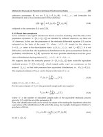
constant, k, was calculated according to Eq. (2):
()
2
C30
C30
R
d
d/
f
kf
WF
+
+
=− ⋅ , (2)
where f
C30+
represents the weight fraction of heavy oil (carbon number above 30), and W/F
R
is the time factor corresponding to the ratio of the weight of catalyst to the flow rate of
residual oil. The activity of the Zr/FeO
X
catalyst decreased when the sequence of reaction
and regeneration was repeated (Fumoto et al., 2006b). The peeling of zirconia from iron
oxide due to structural changes of the iron oxide catalyst caused the deactivation. The
Zr/Al-FeO
X
catalyst was not deactivated after the reaction and regeneration sequence. The
addition of alumina prevented the structural change of iron oxide. When the reaction was
repeated without regeneration, the Zr-Al-FeO
X
catalyst maintained high activity (Fumoto et
al., 2006c), whereas the activity of the Zr/Al-FeO
X
catalyst decreased without the
Progress in Biomass and Bioenergy Production
296
regeneration. The lattice oxygen of iron oxide was consumed during the reaction, causing a
phase change of the iron oxide of Zr/FeO
X
and Zr/Al-FeO
X
catalysts from hematite to
magnetite. Hence, the catalyst was regenerated by calcinations. In contrast, the hematite of
the Zr-Al-FeO
X
catalyst was maintained after the reaction, leading to stable activity without
regeneration. No correlation was observed between the activity of the catalyst and the
deposition of impurities from residual oil. Accordingly, the Zr-Al-FeO
X
catalyst could be
useful for long-term application in the conversion process of biomass wastes.
01234
0
0.1
0.2
0.3
Zr-Al-FeO
X
Zr/Al-FeO
X
(Without regeneration)
Zr/FeO
X
Number of sequence [-]
Reaction rate constant [h
-1
]
Fig. 15. Change in catalytic activity for the decomposition of heavy oil with a repeated
sequence of reaction and regeneration (Fumoto et al., 2006b, 2006c).
4. Conclusion
New methods for recovering ammonia and ketones from biomass wastes were investigated.
The gaseous ammonia and aqueous ammonium ions were adsorbed effectively on the
adsorbent obtained by treating MAP at 378 K. The adsorption of gaseous ammonia and
aqueous ammonium ions was physical and chemical adsorption, respectively. The ammonia
could be recovered by thermal treating of the adsorbent after the adsorption of ammonia
and ammonium ions, suggesting that the adsorbent is useful for repeated use of the
ammonia adsorption/desorption sequence. Large amounts of ammonia were recovered
from hydrothermally treated cow urine using the adsorbent, without impurities contained
in the urine. Biomass wastes also contain various hydrocarbons. The solid wastes, such as
sewage sludge, were solubilized by hydrothermal treatment, producing black water, and
catalytic cracking of the black water was conducted. As a result, large amounts of acetone
were produced with the zirconia-supporting iron oxide catalyst. Oxygen-containing
hydrocarbons reacted with the active oxygen species generated from steam on the iron
oxide catalyst. Supported zirconia promoted the generation of the active species. Hence, the
yield of acetone increased with the increasing zirconia content in the catalyst. Furthermore,
the complex metal oxide catalyst of iron, zirconium, and aluminum showed stable activity
Recovery of Ammonia and Ketones from Biomass Wastes
297
for the decomposition of heavy oil. Accordingly, the catalyst may be suitable for the catalytic
cracking of biomass wastes.
5. References
Balci, S. (2004). Nature of Ammonium Ion Adsorption by Sepiolite: Analysis of Equilibrium
Data with Several Isotherms. Water Res., Vol.38, No.5, (March 2004), pp. 1129-1138,
ISSN 0043-1354
Bernal, M. P. & Lopez-Real, J. M. (1993). Natural Zeolites and Sepiolite as Ammonium and
Ammonia Adsorbent Materials. Bioresour. Technol., Vol.43, No.1, (1993), pp. 27-33,
ISSN 0960-8524
Chimenos, J. M., Fernandez, A. I., Villalba, G., Segarra, M., Urruticoechea, A., Artaza, B. &
Espiell, F. (2003). Removal of Ammonium and Phosphates from Wastewater
Resulting from the Process of Cochineal Extraction using MgO-Containing By-
Product. Water Res., Vol.37, No.7, (April 2003), pp. 1601-1607, ISSN 0043-1354
Diwania, G. E., Rafiea, S. E., Ibiaria, N. N. E. & Ailab, H. I. E. (2007). Recovery of Ammonia
Nitrogen from Industrial Wastewater Treatment as Struvite Slow Releasing
Fertilizer. Desalin., Vol.214, No.1-3, (August 2007), pp. 200–214, ISSN 0011-9164
Fumoto, E., Tago, T., Tsuji, T. & Masuda, T. (2004). Recovery of Useful Hydrocarbons from
Petroleum Residual Oil by Catalytic Cracking with Steam over Zirconia-Supporting
Iron Oxide Catalyst. Energy Fuels, Vol.18, No.6, (November-December 2004), pp.
1770-1774, ISSN 0887-0624
Fumoto, E., Mizutani, Y., Tago, T. & Masuda, T. (2006a). Production of Ketones from Sewage
Sludge over Zirconia-Supporting Iron Oxide Catalysts in a Steam Atmosphere.
Appl. Catal. B, Vol.68, No.3-4, (November 2006), pp. 154-159, ISSN 0926-3373
Fumoto, E., Tago, T. & Masuda, T. (2006b). Production of Lighter Fuels by Cracking Petroleum
Residual Oils with Steam over Zirconia-Supporting Iron Oxide Catalysts. Energy
Fuels, Vol.20, No.1, (January-February 2006), pp. 1-6, ISSN 0887-0624
Fumoto, E., Tago, T. & Masuda, T. (2006c). Recovery of Lighter Fuels from Petroleum
Residual Oil by Oxidative Cracking with Steam over Zr-Al-FeOx Catalyst. Chem.
Lett., Vol.35, No.9, (September 2006), pp. 998-999, ISSN 0366-7022
Fumoto, E., Tago, T. & Masuda, T. (2009). Recovery of Ammonia from Biomass Waste by
Adsorption on Magnesium Phosphate Derived from Magnesium Ammonium
Phosphate. J. Chem. Eng. Jpn., Vol.42, No.3, (2009), pp.184-190, ISSN 0021-9592
Ganley, J. C., Thomas, F. S., Seebauer, E. G. & Masel, R. I. (2004). A Priori Catalytic Activity
Correlations the Difficult Case of Hydrogen Production from Ammonia. Catal. Lett.,
Vol.96, No.3-4, (July 2004), pp. 117-122, ISSN 1011-372X
Gross, B., Eder, C., Grziwa, P., Horst, J. & Kimmerle, K. (2008). Energy Recovery from
Sewage Sludge by Means of Fluidised Bed Gasification. Waste Manage., Vol.28,
No.10, (2008), pp. 1819-1826, ISSN 0956-053X
Guo, Y., Wang, S. Z., Xu, D. H., Gong, Y. M., Ma, H. H. & Tang, X. Y. (2010a). Review of Catalytic
Supercritical Water Gasification for Hydrogen Production from Biomass. Renewable
Sustainable Energy Rev., Vol.14, No.1, (January 2010), pp. 334–343, ISSN 1364-0321
Guo, X. M., Trably, E., Latrille, E., Carrère, H. & Steyer, J. P. (2010b). Hydrogen Production
from Agricultural Waste by Dark Fermentation: A Review. Int. J. Hydrogen Energy,
Vol.35, No.19, (October 2010), pp. 10660-10673, ISSN 0360-3199
Liu, H. C., Wang, H., Shen, J. G., Sun, Y, & Liu, Z. M. (2008). Preparation, Characterization
and Activities of the Nano-Sized Ni/SBA-15 Catalyst for Producing COx-Free
Progress in Biomass and Bioenergy Production
298
Hydrogen from Ammonia. Appl. Catal. A, Vol.337, No. 2, (March 2008), pp. 138-147,
ISSN 0926-860X
Masuda, T., Kondo, Y., Miwa, M., Shimotori, T., Mukai, S. R., Hashimoto, K., Takano, M.,
Kawasaki, S. & Yoshida, S. (2001). Recovery of Useful Hydrocarbons from Oil Palm
Waste Using ZrO
2
Supporting FeOOH Catalyst. Chem. Eng. Sci., Vol.56, No.3,
(February 2001), pp. 897-904, ISSN 0009-2509
Nelson, N. O., Mikkelsen, R. L. & Hesterberg, D. L. (2003). Struvite Precipitation in
Anaerobic Swine Lagoon Liquid: Effect of pH and Mg : P Ratio and Determination
of Rate Constant. Bioresour. Technol., Vol.89, No.3, (September 2003), pp. 229-236,
ISSN 0960-8524
Nipattummakul, N., Ahmed, I. I., Kerdsuwan, S. & Gupta, A. K. (2010). Hydrogen and
Syngas Production from Sewage Sludge via Steam Gasification. Int. J. Hydrogen
Energy, Vol.35, No.21, (November 2010), pp. 11738-11745, ISSN 0360-3199
Park, S. J. & Kim, B. J. (2005). Ammonia Removal of Activated Carbon Fibers Produced by
Oxyfluorination. J. Colloid Interface Sci., Vol.291, No.2, (November 2005), pp. 597-
599, ISSN 0021-9797
Shen, L. & Zhang, D. K. (2005). Low-Temperature Pyrolysis of Sewage Sludge and
Putrescible Garbage for Fuel Oil Production. Fuel, Vol.84, No.7-8, (May 2005), pp.
809-815, ISSN 0016-2361
Stratful, I., Scrimshaw, M. D. & Lester, J. N. (2001). Conditions Influencing the Precipitation
of Magnesium Ammonium Phosphate. Water Res., Vol.35, No.17, (December 2001),
pp. 4191-4199, ISSN 0043-1354
Sugiyama, S., Yokoyama, M., Ishizuka, H., Sotowa, K., Tomida, T. & Shigemoto, N. (2005).
Removal of Aqueous Ammonium with Magnesium Phosphates Obtained from the
Ammonium-Elimination of Magnesium Ammonium Phosphate. J. Colloid Interface
Sci., Vol.292, No.1, (December 2005), pp. 133-138, ISSN 0021-9797
Sugiyama, S., Yokoyama, M., Fujii, M., Seyama, K. & Sotowa, K. (2007). Recycling of Thin-
Layer of Magnesium Hydrogenphosphate for Removal and Recovery of Aqueous
Ammonium. J. Chem. Eng. Jpn., Vol.40, No.2, (February 2007), pp. 198-201., ISSN
0021-9592
Wang, S. J., Yin, S. F., Li, L., Xu, B. Q., Ng, C. F. & Au, C. T. (2004). Investigation on
Modification of Ru/CNTs Catalyst for the Generation of COx-Free Hydrogen from
Ammonia. Appl. Catal. B, Vol.52, No.4, (October 2004), pp. 287-299, ISSN 0926-3373
Yin, S. F., Xu, B. Q., Zhou, X. P. & Au, C. T. (2004). A Mini-Review on Ammonia Decomposition
Catalysts for On-Site Generation of Hydrogen for Fuel Cell Applications. Appl. Catal. A,
Vol.277, No.1-2, (December 2004), pp. 1-9, ISSN 0926-860X
Yin, S. F., Xu, B. Q., Wang, S. J. & Au, C. T. (2006). Nanosized Ru on High-Surface-Area
Superbasic ZrO
2
-KOH for Efficient Generation of Hydrogen via Ammonia
Decomposition. Appl. Catal. A, Vol.301, No.2, (February 2006), pp. 202-210, ISSN
0926-860X
Yusofa, A. M., Keata, L. K., Ibrahimb, Z., Majida, Z. A. & Nizamb, N. A. (2010). Kinetic and
Equilibrium Studies of the Removal of Ammonium Ions from Aqueous Solution by
Rice Husk Ash-Synthesized Zeolite Y and Powdered and Granulated Forms of
Mordenite. J. Hazard. Mater., Vol.174, No.1-3, (February 2010), pp. 380-385, ISSN
0304-3894
Zheng, W. Q., Zhang, J., Ge, Q. J., Xu, H. Y. & Li, W. Z. (2008). Effects of CeO
2
Addition on
Ni/Al
2
O
3
Catalysts for the Reaction of Ammonia Decomposition to Hydrogen.
Appl. Catal. B, Vol.80, No.1-2, (April 2008), pp. 98-105, ISSN 0926-3373
16
Characterization of Biomass as Non
Conventional Fuels by Thermal Techniques
Osvalda Senneca
Consiglio Nazionale delle Ricerche (C.N.R.),
Istituto di Ricerche sulla Combustione
Italy
1. Introduction
In the last decades the problem of CO
2
emission in the atmosphere has driven the industry
of power generation towards an increasing use of biomass fuels in addition to conventional
fuels.
Figure 1 reports the well known Van Krevelen diagram for a wide variety of solid fuels. It
can be seen that biomasses are in general characterized by larger O/C and H/C ratios
compared to fossil fuels such as coals. They stand, instead, close to RDFs (refuse derived
fuels). As a matter of fact it is not easy to draw a clear demarcation line between biomass
and RDFs. Biomass itself is a broad category of materials ranging from raw vegetal materials
to solid refuses of industrial and civil origin (wood and agricultural residues, residues of
paper, food and dairy industry, sludge of civil origin etc) .
A further element of despair in this already very broad category of fuels lies in the content
of inorganics and/or metals, which are present in some biomasses at levels distinctively
higher than in traditional fuels. Under this respect biomasses appear even more close to
industrial wastes. The presence of metals and inorganic matter may produce unusual effects
in terms of both energetic and environmental performance.
It has been shown for a variety of solid fuels that the process and reactor design, in
particular the temperature level and the inert/oxidizing nature of the gaseous atmosphere,
determine the reaction path and affects severely the fate of the organic matter [1-2] but is
also expected to determine the fate of inorganic matter and metals.
As far as the organic content is concerned, upon heating under inert atmosphere this
undergoes a combination of thermal cracking and condensation reactions, called pyrolysis,
producing a gas, a liquid (tar) and a solid product (char). Gaseous species generally include
hydrogen, carbon monoxide, methane, carbon dioxide and other incondensable
hydrocarbons; tar consists of chemicals, such as methanol, acetone, acetic acid etc. liquid at
room temperature; char is a carbonaceous type solid containing mainly carbon but also the
residual inorganic matter.
As shown by Senneca et al. [3] heating of a solid fuel in the presence of oxygen may result in
two types of processes depending on the fuel properties and on the process conditions
(oxygen concentration, temperature and heating rate). At low temperature (if under
isothermal conditions), or at low heating rate (if under non isothermal conditions) thermal
Progress in Biomass and Bioenergy Production
300
cracking and condensation reactions are assisted and enhanced by parallel oxidative and
combustion reactions. Char and tar combustion occur in parallel with thermal cracking as
shown by fig. 2A and the resulting gas is rich in CO and CO
2
. For high enough temperature
(under isothermal conditions) or for large particle heating rates (under non isothermal
conditions), purely thermally activated pyrolysis overtakes direct combustion and the
reaction follows the most typical pattern: pyrolysis occurs first, followed by heterogeneous
combustion of the tar and char. The corresponding reduced network is represented in Fig.
2B. It must be noted that volatile matter emission and the formation of an attached or
detached volatile flame further contribute to preventing the occurrence of heterogeneous
oxidation in this case.
Fig. 1. Van Krevelen diagram
Fig. 2. A Reaction path of oxidative pyrolysis
Characterization of Biomass as Non Conventional Fuels by Thermal Techniques
301
Fig. 2. B Reaction path of pyrolysis-char combustion
The presence of metals and inorganic matter in biomass further complicates the scenario and
makes it difficult to predict whether a reaction pathway of type A or B would be active. A first
consequence is that the yields and the chemical composition of gaseous, liquid and solid
products cannot be predicted a-priori and require appropriate consideration of the process
conditions. A second consequence concerns the fate of inorganics and metals themselves,
which is a matter of utmost importance for environmental reasons. The potential hazard of
emission of volatile metals during the pyrolysis/combustion process and of leaching upon
disposal of the final residue is indeed a problem that has already been underlined for a
number of wastes of industrial origin, such as sludges and wastes obtained from the
reclamation of metal from insulated wires and electronic equipments and automobile wastes
[4-9], but also for some wastes that may be included in the category of biomass, for instance
meat and bone meal [10] and residues of the pulp and paper industry [11].
In conclusions the design of thermal processes aiming at the exploitation of biomass as solid
fuels requires a more comprehensive understanding of how process conditions and reactor
design affect the efficiency in terms of energy conversion, yields and chemical composition
of gaseous, liquid and solid products as well as the fate of inorganic matter. In other words
the exploitation of biomass fuels in thermal processes requires biased experimental
investigation of its pyrolysis and combustion behaviour. To this end a diversity of
techniques at the laboratory scale can be used. The present paper discusses the problems
related with the standard laboratory techniques and presents a comprehensive experimental
protocol for the characterization of biomass fuels based on thermal analysis and lab-scale
reactors. Examples of selected fuels are presented to demonstrate and clarify the issue.
2. Conventional experimental techniques
The most commonly used lab scale technique for the study of thermal processes involving
biomass it thermal analysis, because of it apparent simplicity. Thermal analysis is definitely
the easiest and most accurate tool to perform proximate analysis but its natural and most
valuable goal is the kinetic study.
Today it is well known that the most reliable kinetic methods for the analysis of non
isothermal TG experiments are the Friedman plot [12,13], the Kissinger±Akahira± Sunose
plot [13-15] and the Ozawa-Flynn-Wall method [16,17]. A very important point is that this
analysis is easy and reliable in the case of single power law reactions but is more
complicated in the case of parallel reactions. Thermal processes of biomass in fact have often
Progress in Biomass and Bioenergy Production
302
been described using power law kinetic expressions, for a single reaction when one major
event of weigh loss is distinguished, for two or more parallel reactions when two or more
stages of weight loss are observed. This choice is made for sake of simplicity and also
because the method for kinetic analysis of TG curves is well consolidated. In the case of
multiple/competitive reactions in series/parallel some methods for kinetic analysis have
been proposed, but there are few examples of their application.
In any case it must be clear that thermogravimetric analysis can be used confidently to
predict the thermal life of a fuel only at relatively low temperature and heating rate.
Outsiders may misunderstand there are serious problems to apply the results of
thermogravimetric analysis to practical operating conditions of pyrolysers/combustors,
where temperature and heating rates are quite different from those of thermogravimetric
analysis.
The potential of thermogravimetric analysis in the study of thermal processes of biomass is
considerably enhanced by the introduction of simultaneous DSC or DTA and analysis of
evolved gas (EGA) by FT-IR and mass-spectrometry. The former technique reveals the
presence of transitions, particularly important for biomasses rich in minerals and metals,
moreover it gives information on the endothermic/exothermic nature of the processes, thus
contributing significantly to interprete the weight changes events detected by the TG curves.
Again outsiders should not be tempted to use the DSC data obtained during simultaneous
TG/DSC experiments of biomass for a quantitative measure of its heat of
pyrolysis/combustion.
Analysis of gaseous species by FT-IR and MS is also very useful to obtain information on the
type of gaseous species evolved throughout a thermal process and to understand the
reaction paths, but also in this case results must be regarded as qualitative more than
quantitative and caution is needed to extend them to real situation. Examples of this type of
equipment are shown in Fig. 3.
For the study of the yields of biomass pyrolysis the most common experimental approach
is the recourse to purposely made lab furnaces equipped for the collection of tar and the
analysis and tar and gases. Different configurations and different collection systems have
been proposed. An example of this type of equipment is shown in Fig. 4. Typically the
sample is located inside a pyrolysis reactor which is heated by an external electrical
furnace with heating rates in the order of 5-50°C/min. The product is conveyed to a set
of consecutive traps for tar condensation at progressively lower temperature. Tar is
analysed off-line typically by Gass Cromatography. Uncondensables are analysed either
of line or online by different analythical tools, such as GC (off-line) or FT-IR or MS
(on-line).
This type of experiments is able to give quantitative data on the yield of biomass pyrolysis,
however the extrapolation of these results to reaction conditions far from those of the
experiment would again be ingenuous.
3. Experimental protocol
The experimental protocol proposed for biomass fuels couples experiments in a
thermobalance with experiments in lab scale reactors and tests of physico-chemical
characterization of the fuels themselves and of their solid products. It therefore includes
three activities.
Characterization of Biomass as Non Conventional Fuels by Thermal Techniques
303
TG-MS Skimmer
Thermo
balance
Infrared detector
Transfer line
Thermo
balance
Infrared detector
Transfer line
TGA-FTIR experimental set-up.
Fig. 3. TG-MS and TF-FTIR apparati.
1. Physico-chemical characterization of the solid
This includes proximate and ultimate analysis, SEM-EDX, ICP, XRD, Porosimetry by Hg
and/or gas adsorption, Granulometric analysis.
The same set of analysis is applied to the raw sample and to samples of char and ash. The
char is obtained in the necessary amount by pyrolysis in a tubular furnace or in a fluidized
bed reactor at temperatures in the order of 600-800°C in a flow of nitrogen.
Ashes are obtained from complete burn-off of the material in lab scale reactors such as
tubular furnaces or fluidized bed reactors, in air at temperatures in the order of 800°C.
2. Thermogravimetric analysis
This includes three sets of experiments:
TG-IP. pyrolysis under inert conditions;
TG-OP. oxidative pyrolysis;
TG-C. combustion of char.
Progress in Biomass and Bioenergy Production
304
Thermal analysis is carried out in a TG system, possibly coupled with a DSC/EGA
equipment for on-line analysis of the gaseous products. It is important that such devices are
designed to minimize condensation and secondary reactions in the gas phase.
Approximately 10mg of sample are loaded in the pan in each test. Notably the particle size
of the sample must be reduced when possible to 100-200 o µm to minimize heat gradients
inside the particle and mass transfer limitations. An upward flow of gas of 100-200mL/min
is used.
In pyrolysis experiments (TG-IP and TG-OP) the temperature is raised from 25°C to 110°C
and held at 110°C for 5-10min to release moisture. The sample is then further heated up to
850-900°C at a constant heating rate. Heating rates in the range 5-20°C/min are scanned.
During the ramp, 100% He or Ar or N
2
or a mixture of 0.01-21% oxygen in He/Ar/N
2
are
used. The sample is finally held at 850-900°C for 30min, while the gas is switched to 21%O
2
in He/Ar/N
2
to burn the residual char.
Fig. 4. Lab scale pyrolysis reactor.
In experiments of char combustion (TG-C), the char can be prepared in the thermobalance
immediately prior to the combustion test or externally in a lab scale reactor. The char can be
then heated in the thermobalance up to 850-900°C at a constant heating rate in a the desired
mixture of 0.01-21% oxygen. Alternatively the char is heated in He/Ar/N
2
up to a desired
temperature in the range 350-600°C. The gas is then switched to the desired mixture of 0.01-
21% oxygen O
2
to burn the char isothermally.
It must be noted that the conditions chosen for the thermogravimetric experiments have
been used in past experimental campaigns of pyrolysis and combustion of a wide range of
solid fuels. In most cases such conditions proved successful to avoid internal gradients of
heat and gas concentration as well as particle overheating and guaranteed that reactions
took place under kinetic control. However such precautions may result insufficient to
guarantee kinetic control in some cases.
The mass recorded during experiments of pyrolysis and oxidative pyrolysis is worked out
in order to obtain TG plots of m/m
o
versus T and DTG plots of
1
o
oo
df
mm
dm
dT m dT m
∞
−
=−
versus T.
Characterization of Biomass as Non Conventional Fuels by Thermal Techniques
305
where where m, m
o
and m
∞
are the actual weight of the sample, the initial weight of sample
(after the dehumidification stage in pyrolysis and oxidative pyrolysis experiments) and the
weight of the sample residue at the end of the experiment, respectively.
Results were fitted to a power law expression:
1
exp 1
o
oo
dm E m
k
mdt RT m
α
∞
−
−= −
(1)
The kinetic parameters of equation (1) can be obtained by non linear regression analysis of
the DTG curves according to the Friedman and Kissinger methods using general-purpose
regression tools. Data from experiments at heating rate (H
R
) below 20°C/min are used.
The mass loss recorded during experiments of char combustion is further worked out to
calculate:
• the carbon conversion degree f =(mo-m)/(mo-m
∞
)
m, mo and m
∞
being the actual weight of the sample, the initial weight of sample and the
weight of the sample residue at the end of the experiment;
• the instantaneous rate of carbon conversion df/dt
Assuming that a power law kinetic expression of the type
() exp
n
o
g
df
E
Af k p
dt RT
−
=⋅
(2)
is a good approximation in most cases, where p
g
is the partial pressure of the oxygen and
A(f) describes the evolution of instantaneous conversion rate along burn-off.
Accordingly the time τ
0.5
required to achieve 50% conversion reads:
0.5
0.5
0
1
exp
()
n
g
o
df
E
p
kRT Af
τ
−
=
(3)
and the reaction rate averaged over the first 50% conversion:
'
0.5
0.5
0.5
exp
n
o
g
E
Rk p
RT
τ
−
==
(4)
kinetic parameters of equation (4) can be obtained by non linear regression analysis of
average reaction rate over the conversion interval f=[0, 0.5] at different temperature and
different values of oxygen partial pressure. Alternatively an average over a larger
conversion interval can be adopted.
3.
Experiments in lab scale reactors
These include:
TR-IP-SH Experiments of inert pyrolysis with slow heating.
TR-OP-SH Experiments of oxidative pyrolysis with slow heating.
TR-IP-I Experiments of inert pyrolysis under isothermal conditions.
TR-OP-I Experiments of oxidative pyrolysis under isothermal conditions
TR-CC-SH Experiments of char combustion with slow heating
TR-CC-I Experiments of char combustion under isothermal conditions
Progress in Biomass and Bioenergy Production
306
In experiments of slow pyrolysis (TR-IP-SH and TR-OP-SH) typically tubular reactors are
used heated externally by electric furnaces at 5-10°C/min. The vessel with the sample is
placed inside the reactor from the very beginning of the experiment and heated accordingly.
In experiments of pyrolysis under isothermal conditions (TR-IP-I and TR-OP-I) the sample is
fed to the already hot reactor at a given temperature, typically in the range 600-850°C.
Inert pyrolysis is carried out using helium, while for oxidative pyrolysis inert gas is mixed
with a small quantity (0.1-5%) of O
2
. The reaction products are quickly cooled down as they
flow through bubblers held at 0°C and -12°C respectively. Tar captured by the bubblers are
characterized off line by GC or simulated distillation. The gas which passes through the
bubblers is sent directly to a gas analysis system, possibly a micro-GC in order to analyse
the gaseous products on line. These experiments allow to measure the overall yield in gas-
tar and solid products. Further data concern the composition of the tar cumulatively
produced during the test and the profiles of gaseous species evolved as a function of
time/temperature.
In experiments of char combustion at slow heating rate (TR-CC-SH) the same tubular reactor
and experimental procedure as for experiments of slow pyrolysis can be used. In experiments
of char combustion under isothermal conditions (TR-CC-I) the reactor used for experiments of
isothermal pyrolysis can be used or alternatively small scale fluidized bed reactors. In
fluidized bed reactors a bed of inert material such as quarzite can be used with particle size
typically between 300-400 µm. Particles are fed from the top of the reactor at a fixed
temperature (between 500-900°C). During char combustion experiments the gas is initially
nitrogen. After pyrolysis is complete, the gas is switched from nitrogen to an O
2
/N
2
mixture
(with O
2
at values between 4-15%). The profiles of CO and CO
2
evolved as a function of time
can be worked out to evaluate char combustion rate according to the following expressions:
2
()
R
t
CO CO
to
c
RR
ccQdt
f
n
R
tt
+
==
1/s (5)
f: carbon conversion degree
t
R,
t
o
: reaction time,time when oxygen feed started, s
c
CO,
c
CO2:
concentration of CO e CO
2
, mol/l
Q: gas flow rate, l/s
n
C
: moles of carbon fed with the solid fuel, mol
4. Examples of sample preparation and physico-chemical characyterization
tests
In order to explain the experimental protocol proposed in the previous paragraph, results
will be presented here for a set of different biomasses as well as for other carbon rich
materials. The examples have been selected so as to show typical and problematic cases.
As a first example the case of meat and bone meal (MBM) has been chosen, from a
previously published paper [10].
MBM char was prepared in an electrically heated tubular furnace at 650°C for 5min in a flow
of nitrogen. Ashes of MBM were produced in the same electrically heated tubular furnace at
800°C in a flow of air.
Characterization of Biomass as Non Conventional Fuels by Thermal Techniques
307
Elemental analysis, SEM, ICP and granulometric analysis have been carried out on the
above samples The following instruments have been used: LECO CHN 2000 and Perkin
Elmer CHNOS elemental analysers, a Philips XL30 SEM equipped for EDAX analysis, an
Agilent 7500 CE ICP-MS, a Mastersizer 2000 granulometer of Malvern Instruments.
Results are reported in Table 1 and in Fig. 5.
The granulometric analysis of MBM indicate that the sample has a quite dispersed particle
size distribution with average particle diameter of 250μm. In the SEM picture of MBM some
smooth and roughly cylindrical particles can be recognized within the bulk of the material.
The EDAX analysis reveals large amounts of C, O, Ca, P. In comparison the roughly
cylindrical particles are poor in Ca and P and quite rich in C and S.
Fig. 5. SEM picture of MBM
The ICP analyses indicates that raw MBM contains large amounts of Na and Ca, followed by
K, Mg and by small amounts of Fe, Zn, Al, Sr with traces of Ba, Mn, Cr, Co, Pb. The same
metals are found in ashes of MBM produced in the electrical furnace at 800°C, however
upon ashing the amounts of Ca, Mg increase by a factor of 3, those of Al, Na, Fe, Zn by a
factor of 2; K significantly decreases. XRD of MBM reveals that the only crystalline
substance present in MBM is Apatite (Ca10(PO4)6(OH)2).
In order to provide a good example of the tests of characterization of the microstructural
properties the case of three biomass materials, investigated in ref. [18] will also be reported:
namely, wood chips (Pinus radiata), pine seed shells and exhausted olive husk. Porosimetric
analysis was carried out on the raw materials, on chars and on partially reacted chars.
Char samples were prepared in a bubbling fluidised bed reactor operated with nitrogen at
850°C for 5min. A selection of char particles prepared in the fluidised bed reactor were
embedded in a in epoxy resin and cut. Cross-sections were observed under a scanning electron
microscope (Philips XL30 with LaB6 filament) at magnifications up to 50 times. Some char
samples were ground and sieved to particle size <300μm and further reacted with air or up to
10% carbon conversion in an electrically heated tubular furnace operated at 440°C in air.
Progress in Biomass and Bioenergy Production
308
Proximate analysis of MBM
Moisture (as received w%) 6
Ash (as received w%) 20
Fixed carbon (as received w%) 10
Volatile Matter (as received w%) 64
Ultimate analysis
MBM (as received, w%) MBM char (w%)
C 43.4 31.1
H 6.4 1.7
N 9.2 5.1
S 0.4 n.d.
Cl 0.3 n.d.
P n.d. n.d.
Heating Value of MBM (d.b. %w)
HHV (MJ/kg) 15.50
LHV (MJ/kg) 14.47
ICP analysis of raw and ashed material
MBM (as received, ppm) Ash (ppm)
Al
57
108
Na
11422
19498
Fe 138
331
Ca
19832
58541
K
3910
808
Mg 1777
5150
Ba
11
78
Mn
8
31
Sr
37
140
Cr
1
17
Va 0
0
Ni
0
8
Zn
70
139
Ce 0
0
Co
2
9
La
0
0
Pb
10
9
Granulometric analysis
MBM EP1 EP3
d (0.1) μm
6 4 1
d (0.5) μm
124 44 8
d (0.9) μm
706 162 51
Mean d (Surface weighted), μm
16 9 3
Mean d (Volume weighted), μm
252 73 18
Table 1. Characterization of MBM
Characterization of Biomass as Non Conventional Fuels by Thermal Techniques
309
The analysis included mercury intrusion porosimetry, adsorption of N
2
at 77K and of CO
2
at
273K. The porosimetric station consisted in a high-pressure mercury porosimeter Carlo Erba
2000 equipped with a Macropore unit and a Carlo Erba Sorptomatic 1900. Mercury
porosimetry allowed to evaluate the pore size distribution of char in the size range of
200μm>dp>75Å and the % porosity, ε. Nitrogen adsorption results allowed to evaluate BET
surface areas. Data of carbon dioxide adsorption were analysed according to Dubinin
Radishkevich method to evaluate micropore volumes.
Figures 6 A-C show the cross-sections of char particles of wood chips, pine seed shells and
olive husk observed under the scanning electron microscope. The micrographs show that
char from wood chips and pine seed shells has a highly anisotropic pore structure
characterized by parallel channels running in the axial direction (orthogonal to the paper
sheet). This is a consequence of the fibrous structure of the parent biomass. Large pores
and cavities are also evident in the case of olive husk char, but the orientation appears to
be random. A comparison of the three micrographs shows that the solid matrix of the char
from wood chips is the most porous, while that of pine seed shell char is the most
compact.
The cumulative pore size distribution on volume basis for the chars of the three biomass
fuels is reported in Figure 7. Table 2 reports the overall char porosity and density calculated
from porosimetric data. Table 3 reports the BET surface area and the micropore volume of
unconverted char samples and of char reacted with air or with carbon dioxide up to 10%
carbon conversion.
It can be observed that wood chip char is characterized by the lowest density and the largest
porosity, which consists predominantly of macropores (>1μm). Wood chip char has also the
smallest micropore volume of the three chars (0.17 cm
3
/g). Moreover micropore volume of
wood chip chars is scarcely affected by partial conversion both with air and with carbon
dioxide. BET area of wood chip char is negligible after pyrolysis, it increases to 300m2/g
after 10% combustion. Noteworthy the increase in BET surface with the progress of carbon
consumption can be related with the opening up and development of mesopores, while the
increase of micropore volume can be related with the evolution of microporosity [19]. The
observed results therefore suggest that reaction of wood chip char with oxygen opens up
larger pores (macro and mesopores). The extent and the role of microporosity is very limited
in wood chip char.
Olive husk generates a char that is denser than wood chips char and relatively less macro-
porous. The pore size distribution is indeed shifted toward smaller pore sizes. Micropore
volume of the unconverted char is comparable with that of wood chips (0.18 cm3/g) but
increases by 40% after combustion. BET surface increases up to 320m
2
/g after combustion
Altogether results of porosimetric analysis suggest that olive husk char possess a more
extensive network of mesopores compared to wood chip char and again quite modest
microporosity. Moreover mesoporosity develops along with reaction with oxygen.
The char obtained from pyrolysis of pine seed shells has the smallest pore size distribution
and the highest density of the three biomass chars investigated. Its micropore volume is
0.23 cm
3
/g and increases by 32% after combustion indicating a considerable activation of
small pores especially by carbon dioxide. BET area reaches 580 m
2
/g after combustion
suggesting that mesoporosity is significantly developed by oxygen. Altogether results
indicate that pine seed shell char contains a large portion of micro and mesopores prone to
be activated by the reaction.
Progress in Biomass and Bioenergy Production
310
Average pore diameter [μm] ε % Particle density [kg/m3]
Wood chips char 17 91 170
Olive husk char 7.5 80 400
Pine seed shells char 17.5 70 490
Table 2. Results of Hg-porosimetry on three biomass chars
BET area (N2) [m2/g] Micropore volume (CO2) [cm3/g]
Unreacted char
Wood chips char < 1 0.165
Olive husk char < 1 0.183
Pine seed shells char < 1 0.232
Char reacted with air up to 10% conversion
Wood chips char 296 0.175
Olive husk char 320 0.256
Pine seed shells char 579 0.307
Table 3. Results of gas adsorption on unreacted and partially reacted biomass chars
A last example is reported to demonstrate the study of the fate of metals by SEM, ICP and
XRD analysis. The case reported here refers to a bitumen like refuse of the oil industry,
particularly riched in Mo and V. Although this is not a biomass fuel, it is presented here
because it is particularly instructive of the problematic related to the presence of metals.
In addition to the raw material , also char, ashes, a sample of leached material and a sample
of char at intermediate burn-off have been characterized The char was prepared in a tubular
reactor at 600°C in a flow of nitrogen. Ashes were obtained from complete burn-off of the
material in the same reactor in the excess of 800°C. Partial conversion of the char was
accomplished at 600°C in air. Additionally a sample was obtained by overnight leaching of
the raw material in pentane.
SEM and ICP analysis were carried out using a Philips XL30 SEM equipped for EDAX
analysis and an Agilent 7500 CE ICP-MS. XRD measurements were made with a Brucker D8
ADVANCE diffractometer in reflection mode from 3°(2θ) to 70°(2θ) with a step size of
0.03°(2θ) with an energy dispersive detector Sol-X. Porosimetric analysis was carried out by
nitrogen absorption at 77K with a Carlo Erba Sorptomatic.
Results are reported in Tables 4-5 and in Fig 8. Notably the raw material has a very high
carbon content and good calorific value (PCS 34050 kJ/kg). It contains also non-negligible
contents of selected heteroatoms and several impurities, such as S, Cl, Ca, V, Fe, Ni, Mo.
These metals, identified also by XRD, form different crystalline phases: V1.87FeS4, S8V5.44,
V2NiS4, V2Fe0.67S4, V3S4 and V2MoS4. XRD reveals also the presence of a sharp peak at
2θ=26° indicative of the presence of graphitic carbon, probably resulting from catalytic
graphitization. The BET area is 200m
2
/g.
Notably during vacuum treatment prior to nitrogen adsorption tests the sample released a
large quantity of sticky and intensely odorous volatile matter. This sticky matter removed
under vacuum could also be removed by mild heat treatment up to 150°C or alternatively by
leaching the sample with organic solvents such as pentane, as already explained. The
proximate and ultimate analyses and the ICP analysis confirm that such pre-treatments
removed mainly volatile organic matter with very low boiling point which impregnated the
raw sample, while metals remained in the sample.
Characterization of Biomass as Non Conventional Fuels by Thermal Techniques
311
Fig. 6. SEM picture of cross-section of biomass chars. A. Wood chips; B. Pine seed shells; C.
Olive husk
Progress in Biomass and Bioenergy Production
312
Fig. 7. Cumulative pore size distribution of three biomass chars from Hg porosimetry
Lin counts
0
1000
2000
3000
4000
5000
6000
7000
8000
9000
10000
11000
12000
13000
14000
15000
2
-θ
11 20 30 40 50 60 70
Fig. 8. Results of XRD analysis for a residue of the oil industry: raw sample (red), char
produced under inert conditions (black) and partially burned sample (blue).
Upon pyrolysis in nitrogen at 600°C volatile organic matter is further lost whereas metals
mainly remain in the solid residue. Results from XRD characterization of the char
surprisingly show that the sample becomes less graphitic in nature. When the char is burnt
with air in the excess of 800°C the carbon content gradually decreases and the concentration
Characterization of Biomass as Non Conventional Fuels by Thermal Techniques
313
of metals increases. XRD reveals the appearance of vanadium oxides (VO
2
and V
2
O
3
) and a
renewed increase in graphitic order.
The ash composition has been characterized by ICP, and results are reported in Table 5. If
one considers that ash residue remaining after complete burn off of the raw fuel represents
about 10% of the original sample mass, one would expect that the content of metals in the
ash residue should be nearly ten times the corresponding amount in the raw sample.
Inspection of Table 5 suggests that this is not the case. To better appreciate the partitioning
of metals between the solid residue and the leachate (for samples leached with pentane) or
the gas phase (for char remaining after pyrolysis and for the ash residue remaining after
combustion), a partitioning factor α has been reported for all but the raw samples and for
each metal. Based on an ash-tracing concept, the partitioning factor α has been defined as:
,
,
,
,
ik
iraw
re
f
k
re
f
raw
w
w
w
w
α
=
where w
i,k
represents the amount of metal i in sample k (k=pentane-leached sample, char,
ash) and w
i,raw
the amount of the same metal in the raw sample. Similarly, w
ref,k
and w
ref,raw
represent the amounts of a reference metal in sample k and in the raw sample, respectively.
The reference metal was selected so as to meet two constraints: stability upon both heat
treatment and combustion, abundance so as to minimize uncertainties associated with its
quantification. After consideration of different candidates, Nickel proved to be the better
suited reference metal.
Analysis of the partitioning factors provides a clear picture of the relative stability of the
different metals upon pentane-leaching, fuel pyrolysis and combustion, which can be
related to the departure of α from unity. Most metals are relatively stable upon pyrolysis
(with possible exceptions of sodium and lead). More pronounced is the effect of combustion
on selected metals: extensive depletion of Se, Sb, Cd and Hg is observed. The more
pronounced effect is no doubt that associated with Mo, whose abundant content in the raw
residue is only marginally retained in the ash residue after combustion, possibly because of
the large volatility of this metal in the oxidized state.
Raw sample Pentane-leached sample
Moisture 0.1-0.3 0
Volatiles 22.1-23.8 15.1
Ashes 8.7-10.9 15.9
Fixed carbon 66.7-67.5 69.0
Raw sample Pentane-leached sample Char
C 78.3 78.2 77.2
H 4.6 4.1 1.8
N 0.8 1.0 1.0
S 6.5 n.d. n.d.
O
2
(by difference) 0-1.1 n.d. n.d.
Table 4. Analysis (a.r. w%) of refuses of the oil industry. *Minimum and maximum values.