Advances in Biomimetics Part 6 docx
Bạn đang xem bản rút gọn của tài liệu. Xem và tải ngay bản đầy đủ của tài liệu tại đây (14.49 MB, 35 trang )
Learning from Biosilica: Nanostructured Silicas and Their Coatings
on Substrates by Programmable Approaches
167
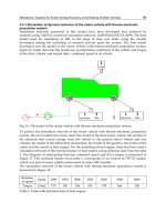
successfully achieved fibrous PEI@silica hybrid structures by using commercial water glass
as source (Figure 5). The nanostructure and morphologies could be controlled by adjusting
polymer concentrations and pH values of the aqueous solution of sodium silicate (Zhu &
Jin, 2008).
Fig. 5. Fibrous PEI@silicas synthesized by using water glass as source. (A) SEM and (B) TEM
images of PEI@silica formed by the mediation of 1 wt% of PEI5050; (C) SEM and (D) TEM
images of PEI@silica obtained by the mediation of sPEI6-200.
3.3 Morphological control of silicas by adjusting the self-assembly of linear PEI
Different to the conventional biomimetic silicification systems based on molecular self-
assembly (Cha et al., 2000; Patwardhan et al., 2005; Pouget et al., 2007; Yuan et al., 2007),
linear PEI-directed silica formation featured with multiple morphogenesis and well-
controlled hierarchical architectures through programmed self-assembly of PEI
macromolecules with linear backbones. The self-assembly of crystalline PEI aggregates
could be controlled by a programmable adjustments of some simple parameters, including
polymer chain architecture and molecular weight, concentrations, additives, media, physical
field and so on. The programmed PEI aggregates are transcribed into silicas with multiple
morpholognesis by performing a biomimetic silicification.
3.3.1 PEI concentration
One of extremely simple method for adjusting PEI self-assembly is to change the
concentrations of PEI in water (Yuan & Jin, 2005b). The concentration effect of silica
morphogenesis was addressed by performing silicification reaction on the aggregates from
PEI505 with concentrations from 5.0 to 0.1 wt% using TMOS as silica source under room
temperature for 40 min (Figure 6). It was found that silicas produced from PEI505 with
concentrations from 2.0-5.0 wt% show fiber-based bundles with a size of several
micrometers. Obviously, the bundles tend to expand in a two-dimensional way, and became
looser when the concentrations of PEI505 decrease. Further decreasing PEI concentration to
≤ 1.0 wt% leads to morphological transformation of silicas from the fiber bundles into
curved leaf-like film. Silicas prepared from PEI505 aggregates of 0.5 wt% concentration
1
μ
m
A
C
1
μ
m
B
D
100 nm
100 nm
Advances in Biomimetics
168
show leaf lamellae composed of interwoven nanofibers, meaning that the silica film grew by
linking separate fibers to each other (Figure 6). The silica film mediated by 0.25 wt% PEI505
was thicker and the fiber structure still could be resolved. When PEI505 concentration
decreased to 0.1 wt%, the silica film shows a smooth surface without fiber structure. It was
assumed that the formation of a thick silica film, which is supported by fiber-to-fiber
linking, is associated with the presence of a large amount of PEI chain that are attached to
the surface of crystalline PEI aggregates.
1
H NMR studies indicated that the relative contents
of amorphous brush on the crystalline PEI fibril dramatically increased as the PEI
concentrations deceased from 0.3 to 0.05 wt%. This means that PEI aggregates obtained from
lower concentrations would favor to offer much more brush sites on crystalline PEI surface,
where the promoted silicification reaction led to the formation of silica film structure.
Fig. 6. Morphological dependence of PEI@silicas on the concentrations of PEI505. SEM
images of PEI@silicas synthesized by PEI505 aggregates with the concentrations of 5, 3, 2,
0.5, 0.25 and 0.1 wt% for (A), (B), (C), (D), (E) and (F), respectively. Bars are 5 μm for A-F and
500 nm for insets of E and F.
3.3.2 Polymer architecture
Multiple morphogenesis of silicas could be generated by designing and using the linear PEI
with different chain architectures (Jin & Yuan, 2005a). As shown in Figure 7A and B, silicas
templated by using PEI5050 aggregates with concentrations of 2 and 0.25 wt% exhibited the
expanded bundle and leaf morphologies, respectively. In contrast, a six-armed star PEI with
a small benzene core (sPEI6-100) directed the formation of silicas with dramatically different
morphologies. A fibrous framework was created by using 2 wt% sPEI6-100 aggregates as
templates (Figure 7C). High-magnification observation reveals that larger fibers are
composed of thinner nanofibers. When the concentration of sPEI6-100 decreased to 0.25
wt%, silicification produced silicas with looser bundle morphologies (Figure 7D). Each silica
bundle was observed to be composed of well-defined nanofibers with the length of tens of
micrometer and the diameters of about 30-50 nm. Compared to PEI5050 (simple linear
architecture), sPEI6-100 (small benzene core with six-arm star architecture) demonstrated
the enhanced ability to form self-assembled aggregates and subsequent silicas with well-
defined unit nanofiber structure. It is very interesting that the silica asters were achieved by
using a star PEI with porphyrin core (p-sPEI4-240). The asters could have more than five
silica arms, which expands towards three-dimensional directions (Figure 7E). The arms
B
F
E
D
C
A
Learning from Biosilica: Nanostructured Silicas and Their Coatings
on Substrates by Programmable Approaches
169
become wider towards the outer of silica asters. Each arm shows serrate end, indicating that
the arms are densely organized with unit nanofibers. The silicas obtained from the lower
content of p-sPEI4-240 (0.25 wt%) still retained the aster morphology.
Fig. 7. Shaping silicas by designing linear PEI backbone into star architecture. SEM images
of PEI@silicas prepared by using PEI5050 with concentrations of 2.0 wt% (A) and 0.25 wt%
(B); using sPEI6-100 with concentrations of 2.0 wt% (C) and 0.25 wt% (D) and p-sPEI4-240
with concentrations of 2.0 wt% (E) and 0.25 wt% (F). The bars are 2 μm for (A-D) and 100 nm
for each inset.
3.3.3 Media for PEI crystallization
By taking advantage of methanol being a good solvent for dissolving crystalline PEI at room
temperature, we developed the strategy to generate shaped silicas by using methanol as a
mediator to adjust the programmed self-assembly of crystalline PEI (Jin &Yuan, 2005b). This
methanol-programmed approach could both enrich the shape generation of silicas and offer
potential advantages of ambient processing of PEI aggregates, which would be of particular
interest in view of applications such as bioactive component immobilization and surface
patterning of silicate-based materials. It was found that the silica morphologies could be
controlled accurately by simply adjusting the amount of methanol addition. Compared to
the obvious nanofiber structure of silica (Figure 8A) formed in neat water, aqueous medium
with 50 vol% methanol addition mediated the silica particles composed of beautiful unit
ribbons (Figure 8B). The unit ribbons have a typical width of 1-2 micrometers and a length
of more than 10 micrometers. Such simple methanol-mediated approach has been also
extended to star PEI for achieving the new silica morphologies (Jin & Yuan, 2006). For
example, 0.5 wt% sPEI4-200 aggregates mediated the formation of very large and curved
silica films composed of unit nanofibers (Figure 8C). In contrast, 50 vol% methanol addition
in media for assembling sPEI4-200 aggregates led to the formation of well-defined fan-like
silicas with very dense aggregation of unit fibers (Figure 8D). 0.3 wt% sPEI4-200 in a
medium with 30 vol% methanol content directed fanlike silicas with relatively loose
aggregation and flowerlike silicas with loose petals (Figure 8F). In contrast, only nanofiber-
D
C
F
A
B
E
Advances in Biomimetics
170
based silica films formed when using neat water as media (Figure 8E) under the same
conditions. We also found that such morphological changes with methanol addition did not
depend on the heating history of PEI aggregates formation, indicating that methanol-water
media composition merely determined the PEI self-assembly. We propose that the addition
of methanol in media could retard the nucleation of PEI crystalline, and thus the growth of
crystallites was limited within relatively small domains. This slow and suppressed
aggregation and/or crystallization process would be favorable to construct the ribbon-like
or fan-like structure. This assumption was supported by our experimental observation. The
aggregate formation in neat water media was observed to take several minutes when
cooling the hot solutions of PEI5050 or sPEI4-200, whereas the complete aggregation in the
methanol-modulation process usually needs several hours, especially for the systems with
higher methanol contents.
Fig. 8. Control of PEI@silica morphology by MeOH mediation. PEI@silicas were synthesized
by using aggregates: (A) 1.0 wt% PEI5050 in water; (B) 1.0 wt% P5050 in a mixture of water-
MeOH (1/1 in volume ratio); (C) 0.5 wt% sPEI4-200 in water; (D) 0.5 wt% sPEI4-200 in a
mixture of water-MeOH (1/1 in volume ratio); (E) 0.3 wt% sPEI4-200 in water; (F) 0.3 wt%
sPEI4-200 in a mixture of water-MeOH (30 vol% MeOH). The bars are 2 μm for A-F and 500
nm for the inset of E.
3.3.4 Acid additives
The ethyleneimine units of PEI could associate with acidic molecules by hydrogen bonding
interaction to form complexes. Therefore, such complexation could also be used to control
the PEI aggregation and subsequent direct silica morphologies (Jin & Yuan, 2007a). We
selected the acid molecules of HCl, poly(ethylene glycol) bis(carboxymethyl) (BA) and
tetra(p-sulfophenyl)porphyrin (TSPP) with functional protons 1, 2 and 4 in one molecule.
Given that protonated segments of linear PEI are freely soluble in water, the partial
protonation of linear PEI could allow the modification of crystalline aggregates of PEI,
leading to the formation of new structure and morphology. The silicas formed without HCl
addition showed silica network with dense nanofiber structure (Figure 9A). In contrast,
silicification of 1 wt% PEI5050 aggregates prepared from 10
-5
M HCl produced silicas
composed of relatively looser network structure and unit nanofibers with increased
diameter (Figure 9B). This could be attributed to the formation of PEI nanofibers with
A
B
E F
C
D
Learning from Biosilica: Nanostructured Silicas and Their Coatings
on Substrates by Programmable Approaches
171
increased density or thickness of PEI amorphous shell due to the suitable protonation
degree of PEI backbone by HCl addition. Further increase of the concentration of HCl was
found to damage the nanofiber structure of silica. The silicas mediated by the aggregates
prepared in 10
-2
M HCl solution showed olive-like shape (Figure 9C). Many silica nanofibers
of about 1 μm length grew from the surface of the particles. Obviously, HCl addition in
increased amount is capable of directing 3-demensional silica structures composed of silica
nanofibers.
Fig. 9. Shaped PEI@silicas synthesized by templating PEI5050 aggregates without acid
additive (A) and with the mediation of 10
-5
M HCl (B), 10
-2
M HCl (C), 10
-2
M BA600 (D), 10
-2
M BA250 (E) and TSPP ([EI]/[TSPP]=1200/1, 30 vol% MeOH addition) (F). The PEI5050
concentrations are 1.0 and 0.3 wt% for (A-E) and (F), respectively. The bars are 2 μm for each
case.
Different to inorganic HCl, addition of bifunctional organic acids, poly(ethylene glycol)
bis(carboxymethyl) ethers with molecular weights of ca. 250 and 600 (denoted as BA250 and
BA600) could adjust the properties and morphologies of the crystalline aggregates of linear
PEI, by physical cross-linking via formation of hydrogen bonding. Upon silificifying the
aggregates self-assembled from PEI by addition of 10
-2
M BA600 (Figure 9D) and BA250
(Figure 9E), it was found that micro-scaled plate-like silica particles were formed. However,
the nanostructures of particles showed the difference between BA600 and BA250 addition.
The silica particles from BA250 addition appear much denser in comparison with the silicas
mediated by BA600 association, and almost no fibrous structure could be observed from the
silica particles obtained from BA250.
A four-armed star PEI with porphyrin core (p-sPEI4-240) can direct silica into a beautiful
aster structure (Jin & Yuan, 2005a), which is dramatically different to silica mediated from
simple linear PEI. The specific aggregation of porphyrin residues was assumed to play the
important role for affording the 3-D self-assembly of PEI crystalline unit. This assumption
was exploited to design the silica morphology by incorporating TSPP (a porphyrin
possessing four sulfonic groups) into linear PEI. By silicifying PEI505 aggregates formed in
an aqueous system containing 30 vol% methanol, 0.3 wt% PEI505 and a trace of TSPP (in a
molar ratio of EI/TSPP at 1200/1), the beautiful flower-like silica particles with micrometer
A
F E D
CB
Advances in Biomimetics
172
size were achieved (Figure 9F). In the flower-like particles, many silica petals with the width
of 500-1000 nm and the length of several micrometers grew from the center in a radiation
way. Clearly, the participation of TSPP in the self-assembly of crystalline aggregates of
PEI505 efficiently promoted the formation of 3-D silica structure (flower-like). This is
consistent with the formation of 3-D aster silicas from p-sPEI4-240.
In addition to the impressive shape control, another important merit for TSPP mediation is
that this process simultaneously produced the photo-functionalized hybrid silicas materials.
The UV-vis spectrum of the stock solution of PEI and TSPP in methanol showed a typical
spectroscopic line due to the molecular state of porphyrin. In contrast, the spectroscopic line
of the trapped TSPP in the shaped silicas changed remarkably; the soret band became very
broad with a red-shift from 418 to 423 nm, and the Q-bands also shifted toward longer
wavelengths, indicating that the porphyrin residues are in a stacking state in the shaped
silica. For silicas mediated from TSPP addition, we suggested that two sets of interactions
could be a cooperative trigger to induce subtle PEI self-assembly. One set is the association
of TSPP with PEI by hydrogen bonding interaction, and the other set is the aggregation
between prophyrin planes by π-π stacking. These shaped silicas with PEI/TSPP are expected
to be used in photonic, electronic and catalytic fields due to the porphyrin functions.
3.3.5 Metal ions as additives
Metal cations should be efficient candidates for regulating the nucleation and growth of
LPEI crystals with defined morphologies, as PEI is a strong coordinator to form complexes
(Zhu et al., 2007). The PEI aggregates with the mediation of metal ions were prepared by
slowly cooling hot aqueous solutions of PEI containing three groups of metal cations with
different valences (monovalent cations: Li
+
, Na
+
, K
+
; divalent cations: Cu
2+
, Co
2+
, Zn
2+
, Mn
2+
;
trivalent cations: Al
3+
, Eu
3+
, Fe
3+
, In
3+
). The silicification was performed by mixing the
aggregates with TMOS and methanol at room temperature for 40 min. It was found that
bulky, turbine-like and urchinlike silica, were produced by mediation of Na
+
, Cu
2+
and Al
3+
with the ratios of EI to metal ions of 20/1, respectively (Figure 10A, B and C). It seems that
the Na
+
ion suppressed fiber formation completely. The cross-sectional transmission
electron microscopy (TEM) image for Cu
2+
-mediated silica revealed that the unit blade of
turbine-like is about 200 nm in width, and 20 nm in thickness. The urchin-like silicas from
Al
3+
addition showed a globular shape with numerous fine, needlelike fibers approximately
20 nm in width. Recently, detailed studies on the formation of 2-D turbine-like structures
were performed by selecting M
II
(p-TolSO
3
)
2
as additives (Matsukizono et al., 2009). All silica
structures from mediation of Cu
II
, Fe
II
, Ni
II
, Co
II
, Zn
II
, Mn
II
are composed of leaf-like units of
200 nm width, which are bundled and grew in radial fashion to form 2-D turbine-like
microstructures with a diameter of 5-6 μm. In contrast, for non-coordinative ion,
tetraethylammonium p-toluenesulfonate salts (NEt
4
(p-TolSO
3
)), only fibrous aggregates
were observed. It is clear that these 2-D structures were induced by the coexisting metal
salts with coordinative ability. The interactions between metal ions and amine groups seem
to be the main factor for promoting 2-D shaped structures. Further studies indicated that the
turbine structure could be controlled by changing the ratios of [EI]/[M
II
] (Figure 10D, E and
F) and self-assembly time of PEI-M
II
in water (Figure 10G, I and J). At 1000/70 of [EI]/[Ni
II
],
2-D turbine-like structures are obtained. These well-shaped structures became more swollen
as Ni
II
ions decreased from 70 to 40 mM. Further decrease of Ni
II
concentration down to 20
mM leads to the formation of rougher aggregates of blade-like components in a more
Learning from Biosilica: Nanostructured Silicas and Their Coatings
on Substrates by Programmable Approaches
173
randomly bundled fashion, which is similar to those obtained from non-metal containing
linear PEI aqueous solutions. In this system, growing times of PEI crystalline precipitates
influenced the silica structures. For examples, the crystalline precipitates formed after 80
min lead to structured silica with two narrow fan-like edges. After that, new sheets were
generated in both sides of each edge and these edges grew in a fan-like fashion with time.
Finally, the fan closed to form turbine-like structures after 140 min.
Fig. 10. SEM images of shaped silicas from self-assmebled PEI aggregates mediated from
metal ions. (A), (B) and (C) are synthesized by the mediation of Na
+
, Cu
2+
and Al
3+
,
respectively, with the molar ratio of EI to metal ions of 20/1. (D), (E) and (F) are prepared by
templating the aggregates from PEI5050 solution containing Ni
II
(p-TolSO
3
)
2
with the
concentrations of 70, 40 and 20 mM of Ni
II
ions ([EI]=1000mM), respectively. (G), (I) and (J)
are morphological evolution of silica altered by pre-structured PEI5050 formed in Zn
II
(p-
TolSO3)2 aqueous solutions ([EI]=1000 mM, [Zn]=60 mM) at times of 80, 110 and 140 min,
respectively. The bars are 2 μm for each case.
3.3.6 Physical field
The programmed self-assembly of linear PEI could be also simply adjusted by changing the
physical field for the formation of crystalline PEI (Yuan & Jin, unpublished results). Using
external physical field is of great interest due to that we don’t need design and synthesize
new polymer for shaping silica into complex morphologies and hierarchical nanostructure,
which is relatively complex and time-consuming. Silica network composed of nanofibers of
A B
F
E
D
C
J I
G
Advances in Biomimetics
174
about 30 nm width was formed by silicifying the crystalline aggregates formed by naturally
cooling the 1.0 wt% PEI5050 hot solution (80
o
C) to room temperature (Figure 11A). In
contrast, the width of fibrous silicas increased to about 500 nm - 1 μm when PEI aggregates
were prepared by cooling the same hot solution with slow rate (Figure 11B). Obviously, the
slowly cooling process enables the PEI molecules to have longer time to crystallize into
objects with lager size. On the other hand, we also tried to freeze the molecular solution of
PEI by immersing hot solution of PEI into mixture of ice-water and acetone-dry ice (-70
o
C).
After the temperature of frozen PEI solution was naturally back to room temperature, the
PEI aggregation occurred. It is interesting that the sample from ice freeze showed the
formation of silica plate (Figure 11C), and freeze from acetone-dry ice resulted in bulk-like
silica composed of folded film (Figure 11D).
Fig. 11. Shaping silicas by physical field. (A) was prepared by using aggregates formed by
naturally cooling 80
o
C aqueous solution of PEI5050 to room temperature; (B) was obtained
by templating the aggregates formed by keeping 80
o
C aqueous solution of PEI5050 at 50
o
C
for 1 h and then naturally down to room temperature; (C) and (D) were formed by using PEI
aggregates prepared by immersing 80
o
C aqueous solution of PEI5050 into a bath of ice-
water and acetone/dry ice, respectively, and then allowing iced samples back to room
temperature naturally. All samples have the same concentration of 1.0 wt% PEI5050.
3.3.7 Fluorescent silica nanoparticles with controlled diameters
Well-defined silica nanoparticles with controlled size and tunable functions are interesting
especially for biomedical applications. Conventional Stöber method (Stöber et al. 1968) for
the synthesis of silica nanoparticles requires harsh conditions and needs care for particle
control. Recently, there have been some reports describing the biomimetic synthesis of silica
spheres mediated by bio-polyamines or synthetic linear or dendrimer polyamines (Knecht &
Wright, 2004; Li et al., 2009), however, the precise particles size control and facile
functionalization still is a challenge. By simply adjusting the media compositions for PEIs
with linear backbone, we are able to generate the uniformed silica nanoparticles
functionalized with acidic dyes by one-port manner (Jin & Yuan, 2007b). By optimizing
10
μ
m
A
10 μm
1
μ
m
5
μ
m
500 nm
B
C
D
1
μ
m
10
μ
m
1
μ
m
Learning from Biosilica: Nanostructured Silicas and Their Coatings
on Substrates by Programmable Approaches
175
Fig. 12. Uniformed silica nanoparticles synthesized by the mediation of linear
poly(ethyleneimine)s and dyes. (A) Fluorescent microscopic and (B) SEM images of silica
nanoparticles prepared by using sPEI4-50/TSPP (1200/1 in molar ratio). (C) Fluorescence
spectra of sPEI4-50/TSPP solution and (D) TSPP-entrapped silica spheres with diluting the
concentrations.
medium composition of methanol/water to be 7/3 in volume, the linear-backbone-based
PEIs with different architectures and/or addition of TSPP directed the formation of
monodisperse silica nanospheres with silicification reaction time of 1 h at room temperature
(Figure 12A and B). The diameters of silica nanoparticles could be controlled from 50 to 700
nm by adjusting the polymer architectures, additives or solution conditions for silica
mineralization. The attractive feature in our approach is that photofunctional dyes could be
simultaneously and simply encapsulated into the resulting silica spheres. The precursor
PEI/TSPP (1200/1) and silica nanoparticles by silicifying precursor PEI/TSPP showed the
same peak position of absorption spectra, indicating that the porphyrin residues entrapped
in the silica spheres exist as molecularly distributed state (i.e., isolated without stacking).
This is very different to that of aster- and flower-like silicas prepared from p-sPEI-240 and
PEI505/TSPP (1200/1 in molar ratio), respectively. Fiber-based 3-D silicas were synthesized
by templating the crystalline PEI aggregates formed in pure water (p-sPEI-240) or in
methanol/water (5/5 in vol., PEI505/TSPP). In contrast, the silica nanoparticles were
formed by using a medium of methanol/water (7/3 in vol.), in which PEI do not crystallize
due to the excess presence of methanol. To further understand the spectroscopic properties
of these silica nanoparticles, the dependence of intensities of absorption and emission on the
concentrations was examined. We found that absorption intensities of both PEI/TSPP
precursor and PEI/TSPP/silica nanoparticles increased with increasing concentrations (Jin
& Yuan, 2007b). However, the emissions of PEI/TSPP precursor and PEI/TSPP/silica
nanoparticles in methanol showed different behavior upon concentration change. The
550 600 650 700 750 800
-50
0
50
100
150
200
250
300
350
400
diluted
F /a.u.
Wavelength /nm
550 600 650 700 750 800
0
200
400
600
800
1000
550 600 650 700 750 800
0
2
4
6
8
10
12
14
16
1%
Concentrated
F /a.u.
Wavelength /nm
A B
D
C
1
μ
m
Diluted
Diluted
Advances in Biomimetics
176
emission intensity (at 650 nm) of the original methanol solution of PEI/TSPP precursor is
very weak, compared to those from diluted solutions (Figure 12C). This is due to the
dynamic-induced self-quenching of TSPP at higher concentration, suggesting that porphyrin
residues are not tethered to the star polymer and thus are in movement with collision.
However, the emission intensity of the PEI/TSPP/silica nanoparticles in methanol increased
upon increasing concentrations (Figure 12D), indicating that TSPP residues with PEI were
almost completely encapsulated in the silica nanospheres and existed as isolated state. The
dye entrapped into silica nanospheres did not show bleach even dispersed in methanol for
over one year. Thus these novel TSPP-functionalized silica nanoparticles would be superior
to some of conventional dye-encapsulated silica nanoparticles based on Stöber routes by
either using silica source with chemically-bonded-dyes or physically doping dyes into silica
network, in which dye incorporation is not easily controllable (Chan et al., 2004).
3.4 Linear PEI for mineralization of other oxides, metals and salts
Titanium oxides, as one of the most useful semiconductors, have been applied in a wide
area due to their many promising properties. Conventional process has made progress on
tailoring TiO
2
into precisely controlled nanostructure, however titania deposition normally
occurred under harsh conditions. Inspired by biosilica formation, biomimetic synthesis of
titania materials have been attempted by using various biologically-derived molecules or
synthetic polyamines (Brutchey & Morse, 2008). However, it remains difficult to construct
TiO
2
materials with definite morphologies (i.e. fiber-like) and characteristic function by this
process. Our recent work demonstrated that well-shaped fibrous networks of PEI@TiO
2
hybrids (Figure 13) could be controllably prepared in an aqueous solution at room
temperature by using crystalline PEI aggregates as a regulator and water-soluble titanium
bislactate as source (Zhu & Jin, 2010). Fibrous hybrids were found to be composed of
anatase nano crystallites (Figure 13B and C) and linear PEI with a regularly-layered
structure. The morphologies and structures of TiO
2
-PEI hybrids depended on pH of reaction
systems and concentrations of PEI and titania source. Recently, Zhao and co-workers also
described using fibrous PEI aggregates as template to direct the low-temperature formation
of nano-branched aluminum–magnesium hydroxide (Xiang et al., 2008).
Fig. 13. (A) SEM image of fibrous PEI@titania hybrids synthesized by simple and efficient
aqueous process regulated by linear polyethyleneimine aggregates, (B) TEM (inset) and
HRTEM image of synthesized PEI@titania, indicating the formation of very tiny crystalline
domains and (C) TEM (inset) and HRTEM images of fibrous titania formed by calcining
PEI@titania at 500
o
C.
5 nm
1 μm
5 nm
200 nm
1
μ
m
A
BC
Learning from Biosilica: Nanostructured Silicas and Their Coatings
on Substrates by Programmable Approaches
177
On the other hand, polymers with linear PEI backbone have been also examined to
mineralize metals into various structure and morphologies. For example, with the use of
low-molecular-weight linear PEI or alkylated PEI (with repeated units of EI of around 8) to
serve as a reducing agent and a protective agent, HAuCl
4
was reported to be induced to
form gold nanoparticles and nanoplates through either a thermal process or room
temperature (Chen et al., 2007). We are interested in using high-molecular-weight linear PEI
with self-assembled crystalline property for reduction and stabilization of metal ion. By
simply mixing the aqueous dispersion of crystalline PEI aggregates with AgNO
3
aqueous
solution at room temperature, an Ag nanoparticles-PEI paste could be obtained. The
macroporous silver frameworks have been achieved by calcining the Ag nanoparticles-PEI
pastes (Jin & Yuan, 2005c). We found that the porous silver frameworks could be tunable
into dome-like shapes with the inner chambers or monoliths with shape-preservation by
simply adjusting some synthesis parameters.
Recently, Taubert and co-workers (Shkilnyy et al., 2008) reported that PEI could be an
efficient template for the controlled mineralization of calcium phosphate. It was found that
spherical calcium phosphate/polymer hybrid particles were formed at pH values above 8
through a mineralization-trapping pathway, where small calcium phosphate particles
formed at the initial step were stabilized by protonated PEI. Comparative studies revealed
that branched and linear PEIs did not show significant difference for calcium phosphate
mineralization, since PEIs were only used as pH-responsive cationic polymer for modifying
crystal growth of calcium phosphate. Self-assembling property of linear PEI due to aqueous
crystallization was not involved in the morphological creation of calcium phosphate, as seen
in the mineralization of silica, titania or metals.
3.5 PEI@oxides as nanoreactors for generating metal nanoparticles
One of important characters of our PEI@oxides materials are that the PEI occluded in
hybrids is still available for subsequent chemical reactions, leading to the facile synthesis of
novel composite materials. The central PEI entrapped in the silica fiber could be used as a
nanoreactor to synthesize metallic nanostructures (Yuan et al. 2006). The reduction of
Na
2
PtCl
4
was simply performed by keeping an aqueous mixture of PEI@silica nanofiber and
Na
2
PtCl
4
for 30 min at room temperature and then aged at 80
o
C for another 30 min, without
any additive reducing agents. XRD measurement indicated the formation of a face-centered
cubic (fcc) lattice of the platinum crystal structure. HRTEM studies demonstrated the
formation of Pt@silica nanocables with the Pt central nanowires of about 3 nm in width
(Figure 14A). Surprisingly, when irradiated with a strong electron beam, the Pt nanowire in
the silica nanotube broken into individual nanoparticles (Figure 14B). The in situ formation
of Pt and Au nanoparticles in PEI@silica prepared using water glass as silica source has also
been successfully achieved (Zhu & Jin, 2008). These metal nanoparticles functionalized silica
materials were expected to have potentials for catalysis or optic application. Furthermore,
PEI residues in the PEI@TiO
2
hybrids have been also exploited to reduce Na
2
PtCl
4
into Pt
nanoparticles by simply mixing PEI@TiO
2
with
the reactants at room-temperature (Zhu &
Jin, 2010). TEM studies indicated that the fibrous morphologies remained undestroyed after
the formation of metallic nanoparticles (Figure 14E). The further HRTEM images showed
that the Pt nanoparticles in situ formed have a typical diameter of about 3 nm, are
homogeneously distributed in the hybrid fibers (Figure 14F). These nanostructured TiO
2
doped with Pt nanoparticles revealed visible light responsible photocatalytic power in
decolorization of dyes.
Advances in Biomimetics
178
Fig. 14. PEI@silica or PEI@titania hybrids as microreactors for in situ formation of Pt
nanoparticles. (A and B) PEI@silica hybrid from TMOS source; (C and D) PEI@silica hybrids
from water glass as source; (E and F) PEI@titania hybrids.
4. Concluding remarks and future outlook
It is important for device and sensor application to biomimetically construct nanostructured
ceramic surface on substrates. It has been a number of reports describing the biomimetic
formation of silica (Yang et al., 2009; Rai & Perry, 2009) and titania (Kharlampieva et al.,
2008) film on the solid substrates. Although some reports have been successful to control
film thickness, particles packing, or patterns, constructing the silica film with high-degree
controllable nanostructure on the arbitrary substrates is still a challenge. Very recently, we
have successfully constructed the silica nanograss on the arbitrary substrates with any
shapes by extending the programmed self-assembly of linear PEI from solution (silica
powder) to interface (silica nanograss) (Figure 15) (Jin & Yuan, 2009). Such a process has
been expanded for the formation of nanofiber-based titania surface, which demonstrated the
photoresponsive surface wettability (Yuan & Jin, 2010a). These novel interface materials
with controlled nanostructure and surface morphology are expected to have potential
applications as microreactors, sensors, microfluidic devices, surface with designer
wettability (Yuan & Jin, 2010a; 2010b) and so on. Moreover, the further functionalization of
such silica nanograss is possible by exploiting the chemistry of PEI and conventional silica,
allowing our interface materials to be applicable in a wide variety of emerging
nanotechnology. On the other hand, although the biomimetic silicas have many amazing
features including ambient-conditions synthesis, potentially precise control over
nanostructure and good biocompatibility, the commercial application still remains a big
challenge. One of major reason is that most of currently-developed systems for biomimetic
20 nm
20 nm
A B
D C
20 nm
50 nm 10 nm
F
E
400 nm
5 nm
Learning from Biosilica: Nanostructured Silicas and Their Coatings
on Substrates by Programmable Approaches
179
silica formation are not easy to scale up, and suffer from high cost, low reproducibility and
relatively poor morphogenesis. Recently, we have optimized the conditions to achieve a
low-cost and reproducible synthesis of several hundred gram scale of silica nano ribbons.
Silicification was performed in neat water under room temperature by using a cheap,
commercially-available silica source. This achievement on biomimetic silica synthesis would
make it possible to develop the related technological applications in a wide range of fields.
Fig. 15. PEI@silica nanograss on arbitrary substrates with. (A) two-step processing for
growing the PEI@silica nanoribbons on substrates; (B) a representative SEM image of
PEI@silica nanograss, the inset is a cross-section image of nanograss; (C) high-magnification
SEM image of PEI@silica nanograss, indicating the blade-like morphology
5. References
Akiyama, Y.; Harada, A.; Nagasaki, Y. & Kataoka, K. (2000). Synthesis of poly(ethylene
glycol)-block-poly(ethylenimine) possessing an acetal group at the PEG end,
Macromolecules, 33, 5841-5845.
Brunner, E.; Lutz, K. & Sumper, M. (2004). Biomimetic synthesis of silica nanospheres
depends on the aggregation and phase separation of polyamines in aqueous
solution, Phys. Chem. Chem. Phys., 6, 854-857.
Brutchey, R.L. & Morse, D.E. (2008). Silicattein and the translation of its molecular
mechanism of biosilicification into low temperature nanomaterial synthesis, Chem.
Rev., 108, 4915-4934.
Cha, J.N.; Shimizu, K.; Zhou, Y.; Christiansen, S.C.; Chmelka, B.F.; Stucky, G.D. & Morse,
D.E. (1999). Silicatein filaments and subunits from a marine sponge direct the
polymerization of silica and silicones in vitro, Proc. Nat. Acad. Sci. USA, 96, 361-365.
Cha, J.N.; Stucky, G.D.; Morse, D.E. & Deming, T.J. (2000). Biomimetic synthesis of ordered
silica structures mediated by block copolypeptides, Nature, 403, 289-292.
N
H
Dipping in
hot solution
Source
solution
Dipping
at r. t.
A
B
C
5
μ
m
5
μ
m
500 nm
Advances in Biomimetics
180
Chan, Y.; Zimmer, J.P.; Stroh, M.; Steckel, J.S.; Jain, R.K. & Bawendi, M.G. (2004).
Incorporation of luminescent nanocrystals into monodisperse core-shell silica
microspheres, Adv. Mater., 16, 2092-2097.
Chatani, Y.; Tadokoro, H.; Saegusa, T. & Ikeda, H. (1981). Structural studies of
poly(ethylenimine). 1. Structures of two hydrates of poly(ethylenimine):
sesquihydrate and dehydrate, Macromolecules, 14, 315-321.
Chatani, Y.; Kobatake, T.; Tadokoro, H. & Tanaka, R. (1982). Structural studies of
poly(ethylenimine). 2. Double-stranded helical chains in the anhydrate,
Macromolecules, 15, 170-176.
Chatani, Y.; Kobatake, T. & Tadokoro, H. (1983). Structural studies of poly(ethylenimine). 3.
Structural characterization of anhydrous and hydrous states and crystal structure
of the hemihydrate, Macromolecules, 16, 199-204.
Chen, C.C.; Hsu, C.H. & Kuo, P.L. (2007). Effects of alkylated polyethylenimines on the
formation of gold nanoplates, Langmuir, 23, 6801-6806.
Croce, G.; Frache, A.; Milanesio, M.; Marchese, L.; Causà, M.; Viterbo, D.; Barbaglia, A.;
Bolis, V.; Bavestrello, G.; Cerrano, C.; Benatti, U.; Pozzolini, M.; Giovine, M. &
Amenitsch, H. (2004). Structural characterization of siliceous spicules from marine
sponges, Biophys. J., 86, 526-534.
Croce, G.; Viterbo, D.; Milanesio, M. & Amenitsch, H. (2007). A mesoporous pattern created
by nature in spicules from Thetya aurantium sponge, Biophys. J., 92, 288-292.
Davis, M.E. (2002). Ordered porous materials for emerging applications, Nature, 417, 813-
821.
Field, C.B.; Behrenfeld, M.J.; Randerson, J.T. & Falkowski, P. (1998). Primary production of
the biosphere: integrating terrestrial and oceanic components, Science, 281, 237-240.
Fuhrmann, T.; Landwehr, S.; El Rharbi-Kucki, M. & Sumper, M. (2004). Diatoms as living
photonic crystals, Appl. Phys. B, 78, 257-6028.
Hashida, T.; Tashiro, K.; Aoshima, S. & Inaki, Y. (2002). Structural investigation on water-
induced phase transitions of poly(ethylene imine). 1. Time-resolved infrared
spectral measurements in the hydration process, Macromolecules, 35, 4330- 4336.
Hildebrand, M. (2008). Diatoms, Biomineralization processes, and genomics, Chem. Rev., 108,
4855-4874.
Hsiue, G.H.; Chiang, H.Z.; Wang, C.H. & Juang, T.M. (2006). Nonviral gene carriers based
on diblock copolymers of poly(2-ethyl-2oxazoline) and linear polyethyleneimine,
Bioconj. Chem., 17, 781-786.
Ji, Q.; Iwaura, R.; Kogiso, M.; Jung, J.H.; Yoshida, K. &
Shimizu, T. (2004). Direct sol-gel
replication without catalyst in an aqueous gel system: from a lipid nanotube with a
single bilayer wall to a uniform silica hollow cylinder with an ultrathin wall, Chem.
Mater., 16, 250-254.
Jin, R.H. & Motoyoshi, K. (1999). Porphyrin-centered water-soluble star-shaped polymers:
poly(N-acetylethylenimine) and poly(ethylenimine) arms, J. Porphyrins
Phthalocyanines, 3, 60-64.
Jin, R.H. (2002a). Controlled location of porphyrin in aqueous micelles self-assembled from
porphyrin centered amphiphilic star poly(oxazolines), Adv. Mater., 14, 889-892.
Jin, R.H. (2002b). Silica-polyoxazoline hybrid with nanosized hollow enclosing porphyrin in
hybrid walls, Chem. Commun., 198-199.
Learning from Biosilica: Nanostructured Silicas and Their Coatings
on Substrates by Programmable Approaches
181
Jin, R.H. (2003a). Self-assembly of porphyrin-centered amphiphilic star block copolymer into
polymeric vesicular aggregates, Macromol. Chem. Phys., 204, 403-409.
Jin, R.H. (2003b). Colloidal crystalline polymer generated in situ from growing star
poly(oxazolines), J. Mater. Chem., 13, 672-675.
Jin, R.H. (2003c). Functional polymeric micelles formed from a novel cationic star block
copolymer, ChemPhysChem, 4, 1118-1121.
Jin, R.H. (2004). Water soluble star block poly(oxazoline) with porphyrin label: a unique
emulsion and its shape direction, J. Mater. Chem., 14, 320-327.
Jin, R.H. & Yuan, J.J. (2005a). Synthesis of poly(ethyleneimine)s-silica hybrid particles with
complex shapes and hierarchical structures, Chem. Commun., 1399- 1401.
Jin, R.H. & Yuan, J.J. (2005b). Simple synthesis of hierarchically structured silicas by poly-
(ethyleneimine) aggregates pre-organized by media modulation, Macromol. Chem.
Phys., 206, 2160-2170.
Jin, R.H. & Yuan, J.J. (2005c). Fabrication of silver porous frameworks using
poly(ethyleneimine) hydrogel as a soft sacrificial template, J. Mater. Chem., 15, 4513-
4517.
Jin, R.H. & Yuan, J.J. (2006). Shaped silicas transcribed from aggregates of four-armed star
polyethyleneimine with a benzene core, Chem. Mater., 18, 3390-3396.
Jin, R.H. & Yuan, J.J. (2007a). Hierarchically structured silica from mediation of linear
poly(ethyleneimine) incorporated with acidic/basic additives, Polym. J., 39, 464-470.
Jin, R.H. & Yuan, J.J. (2007b) One-pot and rapid synthesis of uniformed silica spheres via
mediation of linear poly(ethyleneimine)s and dyes, Polym. J., 39, 822- 827.
Jin, R.H., & Yuan, J.J. (2009) Biomimetically controlled formation of nanotextured
silica/titania films on arbitrary substrates and their tunable surface function, Adv.
Mater., 21, 3750-3753.
Johnson, J.R.; Spikowski, J. & Schiraldi, D.A. (2009). Mineralization of clay/polymer
aerogels: a bioinspired approach to composite reinforcement, ACS Appl. Mater.
Interfaces, 1, 1305-1309.
Kakuda, H.; Okada, T. & Hasegawa, T. (2009). Temperature-induced molecular structural
changes of linear polyethylene imine in water studied by mid-infrared and near-
infrared spectroscopies, J. Phys. Chem. B, 113, 13910-13916.
Kharlampieva, E.; Tsukruk, T.; Slocik, J.M.; Ko, H.; Poulsen, N.; Naik, R.R.; Kröger, N. &
Tsukruk, V.V. (2008). Bioenabled surface-mediated growth of titania nanoparticles,
Adv. Mater., 20, 3274-3279.
Knecht, M.R. & Wright, D.W. (2004). Dendrimer-mediated formation of multicomponent
nanospheres, Chem. Mater., 16, 4890-4895,
Krasko, A.; Lorenz, B.; Batel, R.; Schröder, H.C.; Müller, I.M. & Müller, W.E.G. (2000).
Expression of silicatein and collagen genes in the marine sponge Suberites
domuncula is controlled by silicate and myotrophin, Eur. J. Biochem., 267, 4878-
4887, 4855-4874.
Kresge, C.T.; Leonowicz, M.E.; Roth, W.J.; Vartuli, J.C. & Beck, J.S. (1992). Ordered
mesoporous molecular sieves synthesized by a liquid-crystal template mechanism,
Nature, 359, 710-712.
Kröger, N.; Bergsdorf, C. & Sumper, M. (1994). A new calcium-binding glycoprotein family
constitutes a major diatom cell wall component, EMBO J., 13, 4676- 4683.
Advances in Biomimetics
182
Kröger, N.; Bergsdorf, C. & Sumper, M. (1996). Frustulins: domain conservation in a protein
family associated with diatom cell walls, Eur. J. Biochem., 239, 259-284.
Kröger, N.; Lehmann, G.; Rachel, R. & Sumper, M. (1997). Characterization of a 200-kDa
diatom protein that is specifically associated with a silica-based substructure of the
cell wall, Eur. J. Biochem., 250, 99-105.
Kröger, N.; Deutzmann, R. & Sumper, M. (1999). Polycationic peptides from diatom biosilica
that direct silica nanosphere formation, Science, 286, 1129-1132.
Kröger, N. & Wetherbee, R. (2000a). Pleuralins are involved in theca differentiation in the
diatom Cylindrotheca fusiformis, Protist, 151, 263-273.
Kröger, N.; Deutzmann, R.; Bergsdorf, C. & Sumper, M. (2000b). Species-specific polyamines
from diatoms control silica morphology, Proc. Natl. Acad. Sci. U.S.A., 97, 14133-
14138.
Kröger, N.; Deutzmann, R. & Sumper, M. (2001). Silica-precipitating peptides from diatoms:
The chemical structure of silaffin-1A from Cylindrotheca fusiformis, J. Bio. Chem.,
276, 26066-27070.
Kröger, N.; Lorenz, S.; Brunner, E. & Sumper, M. (2002). Self-assembly of highly
phosphorylated silaffins and their function in biosilica morphogenesis, Science, 298,
584-586.
Kröger, N. & Poulsen, N. (2008). Diatoms-from cell wall biogenesis to nanotechnology, Ann.
Rev. Gene., 42, 83-107.
Li, X.; Yang, T.; Gao, Q.; Yuan, J. & Cheng, S. (2009). Biomimetic synthesis of copolymer-
silica nanoparticles with tunable compositions and surface property, J. Colloid
Interface Sci., 338, 99-104.
Matsukizono, H.; Zhu, P.X.; Fukazawa, N. & Jin, R.H. (2009). Turbine-like structured silica
transcribed simply by pre-structured crystallites of linear poly(ethyleneimine)
bounded with metal ions, CrystEngComm, 11, 2695-2700.
Menzel, H.; Horstmann, S.; Behrens, P.; Bärnreuther, P.; Krueger, I. & Jahns, M. (2003).
Chemical properties of polyamines with relevance to the biomineralization of silica,
Chem. Commun., 2994-2995.
Merchant, S.A.; Tran, T.O.; Meredith, M.T.; Cline, T.C.; Glatzhofer, D.T. & Schmidtke, D.W.
(2009). High-sensitivity smperometric biosensors based on ferrocene-modified
linear poly(ethylenimine), Langmuir, 25, 7736-7742.
Milligan, A.J. & Morel, F.M.M. (2002). A proton buffering role for silica in diatoms.
Science,
297, 1848-1850.
Müller, W.E.G.; Rothenberger, M.; Boreiko, A.; Tremel, W.; Reiber, A. & Schröder, H.C.
(2005). Formation of siliceous spicules in the marine demosponge Suberites
domuncula, Cell and Tissue Res., 321, 285-297.
Müller, W.E.G.; Belikov, S.I.; Tremel, W.; Perry, C.C.; Gieskes, W.W.C.; Boreiko, A.
& Schröder, H.C. (2006). Siliceous spicules in marine demosponges (example
Suberites domuncula), Micron, 37,107-120.
Murr, M.M. & Morse, D.E. (2005). Fractal intermediates in the self-assembly of silicatein
filaments, Proc. Nat. Acad. Sci. USA, 102, 11657-11662.
Navarro, S.; Shkilnyy, A.; Tiersch, B.; Taubert, A. & Menzel, H. (2009). Preparation,
characterization, and thermal gelation of amphiphilic alkyl-poly(ethyleneimine),
Langmuir, 25, 10558-10566.
Learning from Biosilica: Nanostructured Silicas and Their Coatings
on Substrates by Programmable Approaches
183
Patel, P.A.; Eckart, J.; Advincula, M.C.; Goldberg, A.J. & Mather, P.T. (2009). Rapid synthesis
of polymer-silica hybrid nanofibers by biomimetic mineralization, Polymer, 50,
1214-1222.
Patwardhan, S.V.; Clarson, S.J. & Perry, C.C. (2005). On the role(s) of additives in
bioinspired silicification, Chem. Commun., 1113-1121.
Perry, C.C. & Keeling-Tucker, T. (2000). Biosilicification: The role of the organic matrix in
structure control, J. Bio. Inorg. Chem., 5, 537-550.
Pohnert, G. (2002). Biomineralization in diatoms mediated through peptide- and polyamine-
assisted condensation of silica, Angew Chem. Int. Ed., 41, 3167- 3169.
Pouget, E.; Dujardin, E.; Cavalier, A.; Moreac, A.; Valery, C.; Marchi-Artzner, V.; Weiss, T.;
Renault, A.; Paternostre, M. & Artzner, F. (2007). Hierarchical architectures by
synergy between dynamical template self-assembly and biomineralization, Nat.
Mater., 6, 434-439.
Poulsen, N.; Sumper, M. & Kröger, N. (2003). Biosilica formation in diatoms:
Characterization of native silaffin-2 and its role in silica morphogenesis, Proc. Natl.
Acad. Sci. U.S.A., 100, 12075-12080.
Rai, A. & Perry, C.C. (2009). Fabrication of tuneable thickness silica films on solid surfaces
using amines and proteins, Silicon, 1, 91-101.
Saegusa, T.; Kobayashi,S. & Yamada, A. (1975). Graft copolymerization of 2-methyl-2-
oxazoline onto chloromethylated polystyrene and hydrolysis of graft copolymer to
a chelating resin of poly(styrene-g-ethylenimine), Macromolecules, 8, 390- 396.
Schmidt, D.J.; Cebeci, F.C.; Kalcioglu, Z.I.; Wyman, S.G.; Ortiz, C.; Vliet, K.J.V. & Hammond,
P.T. (2009). Electrochemically controlled swelling and mechanical properties of a
polymer nanocomposite, ACS Nano, 3, 2207-2216.
Schröder, H.C.; Boreiko, A.; Korzhev, M.; Tahir, M.N.; Tremel, W.; Eckert, C.; Ushijima,
H.; Müller, I.M. & Müller, W.E.G. (2006). Co-expression and functional interaction
of silicatein with galectin: Matrix-guided formation of siliceous spicules in the
marine demosponge Suberites domuncula, J. Bio. Chem., 281, 12001- 12009.
Schröder, H.C.; Wang, X.; Tremel, W.; Ushijima, H. & Müller, W.E.G. (2008). Biofabrication
of biosilica-glass by living organisms, Nat. Prod. Rep., 25, 455-474.
Shimizu, K.; Cha, J.; Stucky, G.D. & Morse, D.E. (1998). Silicatein α: Cathepsin L-like protein
in sponge biosilica, Proc. Nat. Acad. Sci. USA, 95, 6234-6238.
Shkilnyy, A.; Friedrich, A.; Tiersch, B.; Schone, S.; Fechner, M.; Koetz, J.; Schlapfer, C W. &
Taubert, A. (2008). Poly(ethylene imine)-controlled calcium phosphate
mineralization, Langmuir, 24, 2102-2109.
Sumper, M. (2002). A phase separation model for the nanopatterning of diatom biosilica,
Science, 295, 2430-2433.
Sumper, M. & Kröger, N. (2004a). Silica formation in diatoms: The function of long-chain
polyamines and silaffins, J. Mater. Chem., 14, 2059-2065.
Sumper, M. (2004b). Biomimetic patterning of silica by long-chain polyamines, Angew Chem.
Int. Ed., 43, 2251-2254.
Sumper, M. & Lehmann, G. (2006). Silica pattern formation in diatoms: Species-specific
polyamine biosynthesis, ChemBioChem, 7, 1419-1427.
Smetacek, V. (1999). Diatoms and the ocean carbon cycle, Protist, 150, 25-32.
Stöber, W.; Fink, A. & Bohn, E. (1968). Controlled growth of monodisperse silica spheres in
the micron size range, J. Colloid Interface Sci., 26, 62-69.
Advances in Biomimetics
184
Tréguer, P.; Nelson, D.M.; van Bennekom, A.J.; DeMaster, D.J.; Leynaert, A. & Quéguiner, B.
(1995).The silica balance in the world ocean: a re-estimate, Science, 268, 375-379.
van Bommel, K.J.C. & Shinkai, S. (2002). Silica transcription in the absence of a solution
catalyst: the surface mechanism, Langmuir, 18, 4544-4548.
van Bommel, K.J.C.; Friggeri, A. & Shinkai, S. (2003). Organic templates for the generation of
inorganic materials, Angew Chem. Int. Ed., 42, 980-999.
van de Poll, W.H.; Vrieling, E.G. & Gieskes, W.W.C. (1999). Location and expression of
frustulins in the pennate diatoms Cylindrotheca fusiformis, Navicula pelliculosa,
and Navicula salinarum (Bacillariophyceae), J. Phycol., 35, 1044-1053.
Weaver, J.C. & Morse, D.E. (2003). Molecular biology of demosponge axial filaments and
their roles in biosilicification, Micro. Res. Tech., 62, 356-367.
Yang, H.; Coombs, N. & Ozin, G.A. (1997). Morphogenesis of shapes and surface patterns in
mesoporous silica, Nature, 386, 692-695.
Yang, S.H.; Park, J.H.; Cho, W.K.; Lee, H S. & Choi, I.S. (2009). Counteranion-directed,
biomimetic control of silica nanostructures on surfaces inspired by biosilicification
found in diatoms, Smal, 5, 1947-1951.
Yuan, J.J. & Jin, R.H. (2005a). Fibrous crystalline hydrogels formed from polymers
possessing a linear poly(ethyleneimine) backbone, Langmuir, 21, 3136-3145.
Yuan, J.J. & Jin, R.H. (2005b). Multiply shaped silica mediated by aggregates of linear
poly(ethyleneimine), Adv. Mater., 17, 885-888.
Yuan, J.J.; Zhu, P.X.; Fukazawa, N. & Jin, R.H. (2006). Synthesis of nanofiber-based silica
networks mediated by organized poly(ethylene imine): structure, properties, and
mechanism, Adv. Funct. Mater., 16, 2205-2212.
Yuan, J.J.; Mykhaylyk, O.O.; Ryan, A.J. & Armes, S.P. (2007). Cross-linking of cationic block
copolymer micelles by silica deposition, J. Am. Chem. Soc., 129, 1717-1723.
Yuan, J.J. & Jin, R.H. (2010a). Bioinspired synthesis of continuous titania coat with tunable
nanofiber-based network structure on linear polyethyleneimine-covered substrates,
Langmuir, 26, 4212-4218.
Yuan, J.J. & Jin, R.H. (2010b). Water motion and movement without sticking, weight loss
and cross-contaminant in superhydrophobic glass tube, Nanotechnology, 21, 065704.
Zhu, P.X. & Jin, R.H. (2007). Polyethyleneimine aggregates regulated by metal cations acting
as biomimetic organic reactors for silica architectures, Small, 3, 394-398.
Zhu, P.X. &
Jin, R.H. (2008). Environmentally benign and cost-effective silicification: From
water glass to nanostructured silica by poly(ethyleneimine) mediation, J. Mater.
Chem., 18, 313-318.
Zhu, P.X. & Jin, R.H. (2010). Simple and efficient aqueous process for nanostructured fibrous
TiO2 regulated by linear polyethyleneimine aggregates, Eur. J. Inorg. Chem., 3, 476-
482.
Xiang, T.; Zhao, L.; Li, Y.; Lei, Z.; Jin, S.; Li, S.; Li, Y. & Liang, Y. (2008). Template formation
of aluminum-magnesium hydroxide nano-branches on linear poly(ethylene
imine), Mater. Lett., 62, 1627-1629.
9
Biomimetic Fiber-Reinforced
Compound Materials
Tom Masselter and Thomas Speck
Plant Biomechanics Group Freiburg (PBGF),
Faculty of Biology, Botanic Garden,
University of Freiburg
Germany
1. Introduction
During the last years, many efforts have been made to transfer results of quantitative
analyses of functional morphology and biomechanics in plants into technical applications.
These attempts have been increasingly successful as is proven by the increasing number of
biomimetic products on the market (e.g. paints based on the Lotuseffect® among many
others, see Bar-Cohen (2006) and Masselter et al. (2010a)), of which the top 100 biomimetic
products have generated about 1 billion Euros in 2005 to 2008 (Bushan, 2009). These
successes are the result of the long period over which the form-structure-function
relationships of the plants have been investigated and understood. Of the broad spectrum of
biomimetic products, fiber-reinforced composites represent some of the most successful
biomimetic technical applications. The potential of developing biomimetic fiber-reinforced
compound materials is very high because 1) the fiber-matrix structure in plants is
comparable to those in technical materials and 2) the complex fiber-matrix structures in
plants are organized in at least five hierarchical levels (Masselter et al., 2009b, 2010a; Speck
T. et al., 2007), from the molecular scale over the nanoscale and microscale to macroscale
(Jeronimidis, 2000a). Quantitative analysis of this hierarchical structuring of plants is
generally being increasingly recognized as one of the most important keys for
understanding the form-structure-function relationships in plants (see Fratzl, 2007). This
method allows interpreting and abstracting the interaction between the structural
components in plants that possess different mechanical properties and in consequence,
building a new generation of lightweight but stiff fiber-reinforced biomimetic compound
materials (Masselter 2009b, 2010a,b; Speck, O. et al., 2005; Speck, T. et al., 2007; Speck, T. &
Speck, O. 2008).
In a biomimetic project, dealing with the development of fiber-reinforced compound
materials the most important assets are the biological concept generators, which can be
linear (unbranched) or branched, thereby mirroring the structures that are present in
technics. Branched structures as Y- and T-shaped branched components are very common in
many fields of technical applications (Fig. 1). In plants, these branchings have to bear high
static and dynamic loads that form a complex overlay of different loading modes: bending,
compression-tension and torsion (Jeronimidis, 2000b). In technics, similar loads often
drastically decrease the life time of a technical component causing wear and material fatigue
Advances in Biomimetics
186
(Fig. 1C). This situation is further complicated by the need to join these technical structures
together by welding or riveting. These joints represent potential failure regions as notch
stresses are often very high in these regions (Mattheck, 2007). What’s more, producing these
joinings is time-consuming and costly. In plants, branchings are developed and shaped in a
manner so that notch stresses present in ‘joints’ (i.e. stem-branch attachments) are diverted
and distributed, so that similar zones of weakness do not develop (Mattheck, 1990, 2007;
Mattheck & Tesari 2002; Schwager et al., 2010).
Fig. 1. Supporting structures in bicycle and motorbike engineering. (A) Headset of bicycle,
(B),(C) subframe of motorbike with failure (arrow), (D) metal fork bridge of motorbike. ©
PBGF.
Generally speaking, plants are ‚ideal‘ concept generators for improving branched or
unbranched technical structures since:
- Plants typically ‘avoid’ critical notch stresses
- Plants are lightweight structures
- Plants possess interesting mechanical properties like for example high stiffness and
strength combined with a benign fracture behavior and good damping
- The laminated configuration of technical fiber-reinforced compound materials and the
structure of some plant stems are highly comparable (Fig. 2, Ehrenstein, 2006; Speck T.
et al., 2007)
Fig. 2. Section of carbon-fiber-reinforced laminate (A) and bamboo stem wall (B) (from
Ehrenstein, 2006). Scale bars = 200 µm.
Biomimetic Fiber-Reinforced Compound Materials
187
2. Biomimetic fiber-reinforced compound materials and structures
2.1 Linear ‚unbranched‘ structures
2.1.1 Wood: Hierarchical structuring and microfibril angle
There exist numerous applications in which wood, wood pulp and natural fibers are used as
components in the manufacturing of composites (e.g., Gindl & Jeronimidis 2004) for
improving mechanical, thermal or other beneficial properties. Until now, the potential of
using the hierarchical structure of wood as concept generator for developing innovative
biomimetic fiber-reinforced compound materials has still been too little utilized (Fratzl,
2002b, 2007), even though wood is an excellent example for a complex structure that has led
to several biomimetic applications (see below). The hierarchical structure of wood is well
visible, including stem, tissue (Fig. 3A), cell (Fig. 3B,C) and ultrastructural level (Fig. 3D).
Microfibril angles, i.e., the angles between the microfibrils and the longitudinal axis of wood
tracheids, range typically between 0 and 30 degrees (Fig. 3D).
Fig. 3. Schematic drawing showing the hierarchical structure of spruce wood. (A) Tissue-
level: cross-section of spruce wood; earlywood (EW) can be dinstiguished from the denser
latewood (LW), (B, C) cell level: cellulose microfibril angle differs in (B) (0°) and (C ) (50°)
resulting in a plane fracture surface (B) or a highly structured fracture surface (C) in which
tracheids and part of the tracheid wall are torn out, (D) ultrastructural level: different layers
of a wood fiber tracheid can be distinguished: ML: middle lamella, P: pectin layer, S1-3: cell
wall layers 1-3. The layer S2 represents approx. 80% of the overall thickness. Scale bars: (B)
100 µm; (C) 50 µm. Redrawn from Fratzl (2002a), Lichtenegger et al. (1999), Reiterer et al.
(2001) and Vincent (2003). © PBGF.
When loaded under tension parallel to the longitudinal axis of the tracheids, spruce wood
may show a markedly different fracture behavior (Fig. 3B, C) depending on the values of the
fiber angle in the S2 wall of the fibers (Jeronimidis, 1979, 1980a,b, Fig. 3D). When the angles
are well above 0°, the lignin between the helically arranged cellulose microfibers in the cell
wall fractures (Fig. 3C) (Reiterer et al., 2001). This mechanism allows the tracheids to
elongate, dissipates large amounts of energy and leaves the cellulose microfibers intact, so
Advances in Biomimetics
188
that they are still able to carry a load. Other interesting mechanical properties of wood for
biomimetic applications are its low density, a high Young‘s modulus for resisting
compressive forces, high fracture stress for resisting lateral forces and a large fracture strain
to survive bending.
In a GFRP (glass-fiber reinforced plastic) with helically wound fibrous tubes, failure modes
are very similar (Fig. 4A) to the failure modes of spruce wood (Gordon & Jeronimidis, 1980).
There is a maximum of the work of fracture for a winding angle of 15° if subjected to three-
point bending and tension. Initial failure is due to the resin between the fibers failing in
shear (Fig. 4B). After that, the fibers rotate toward the longitudinal axis of the tubes,
increasingly shearing the matrix and giving rise to further failures (Fig. 4B). This extends the
strain before final failure and absorbs a large amount of energy. Both effects are of high
interest for technical implementations. The findings of Gordon & Jeronimidis (1980) led to a
patented composite material (Fig. 4C), which represents a different way of building a system
of tubes with helically arranged fibers by using corrugation, with an optimal fiber angle α of
about 15 degrees.
The potential fields of technical implementation are manifold, above all in the automotive
industry and particularly in aerospace (Fig. 5) (Mangalgiri, 1999; Zhang et al., 2007). In new
airplanes like the A380, compound materials contribute to 20-22% of the weight (Quilter,
2004). Carbon-fiber reinforced plastic, glass-fiber reinforced plastic and quartz-fiber
reinforced plastic are used extensively in the wings, the fuselage sections, the tail and the
doors ().
Fig. 4. Biomimetic glass-fiber reinforced plastics (GFRP). (A) Fracture morphology for GRFP
with macrofibers, (B) force-displacement curve for GFRP, (C) patented composite material
using optimized orientation of the reinforcing fibers to a corrugated medium. Redrawn from
Caplin et al. (1983) and Gordon & Jeronimidis (1980). © PBGF.
2.1.2 Autonomous actuation and self-adaptation
Passive actuation systems in plants are of special interest for a biomimetic transfer as no
active movements have to be abstracted and transferred into a technical application. Passive
movements of plants or plant organs are mainly caused by changes in environmental
conditions that act on dead tissues and cells (Dawson et al., 1997; Elbaum et al., 2007). Cell
wall swelling or shrinking is effectuated by a combination of stiff cellulose fibrils that are
embedded in different angles in a pliant and highly swellable matrix. Through this
Biomimetic Fiber-Reinforced Compound Materials
189
Fig. 5. Sandwich structure of the fuselage in a modern aircraft. Redrawn from
© PBGF.
Fig. 6. Actuation principles of compound layer models. Different movements can be
achieved by hydrating a swelling layer depending on its joining to a non-swelling layer. (A)
Bending in a layer in which the fibers are parallel in one layer and in the other randomly
organized, (B) rolling and bending in a bimorph layer with fibers and swelling direction of
the two layers at an angle of 90°, (C) twisting and torsion in a similar bimorph layer with
45° angle. Redrawn from Stahlberg & Taya (2006). © PBGF.
structure, plants can generate various actuators by combining tissue layers consisting of
cells with different swelling behavior and therefore elongation when wetted or dry. This
actuator may cause bending, rolling and bending, twisting and torsion of plant organs (Fig.
6) and can cause large deformations. The modes of deformation depend on the relative
Advances in Biomimetics
190
orientation of the cellulose microfibrils and the relative swelling direction of the two tissue
layers (Fig. 6).
One of these actuation principles can be observed in wheat awns (Fig. 7A-C). These elongate
structures are attached to the wheat fruit (Fig. 7A). By a passive movement, they assist in the
dispersion and mobility of the fruit. In the adaxial side of the awn, the cap, the cellulose
microfibrils are almost parallel to the longitudinal axis of the awn, on the abaxial side, the
ridge, the microfibers are randomly organised (Fig. 7B). A change in humidity in the daily
cycle causes differential swelling of the two sides and bending of the awns, by which the
awned fruits dig themselves into the ground. As there are hooks on the abaxial side of the
awns, preventing them from going upward (out of the soil) the fruits are pushed deeper in
the ground (Fig. 7C) with every wetting-desiccation cycle (Burgert & Fratzl, 2009; Elbaum et
al., 2007; Fratzl et al., 2008)
Fig. 7. Passive actuation systems in plants. (A) Dispersal unit of wheat with awns, (B) layers
with axioparallel fibers (adaxial layer) and randomly organized fibers (abaxial layer) that
cause bending (C) in daily cycles (open at day (dry) and closed by night (wet) due to a
change in moisture. These cycles push the fruit in the ground. (D) Uprighting of a conifer
branch by compression wood at the lower side of the branch. The angles in the microfibrils
in normal wood (above) and compressive wood (below) are markedly different.
Hygroscopic swelling increases the length of the compression wood tracheids causing an
upright bending of the branch. (E) Uprighting of an angiosperm tree branch by tension
wood in the upper side of the branch. (F) Model of the functioning principle of tension
wood. Swelling of the gelatinous G-layer fibers (horizontal tubes at upper image) creates
circumferential hoop stresses σ
r
in the tracheid that are converted into axial tensile stresses
σ
a
shortening the length of the tracheid. The ratio between the axial tensile stresses σ
a
and
the radial stresses σ
r
depends on the angle of the microfibrils. Redrawn from Burgert &
Fratzl (2009), Elbaum et al. (2007) and Goswami et al. (2008). © PBGF.
Compression wood (Fig. 7D) as well as tension wood (Fig. 7E) can also act as actuators, by
changing the curvature of the axis of a branch (Fig. 7D,E). In compression wood, swelling
leads to an axial elongation of the wood (Fratzl et al., 2008). In tension wood, swelling leads
to a reduction in axial length, depending in both cases on the angle of the cellulose
microfibrils in the cell wall of the tracheid of wood fibers respectively. In tension wood, if
the structure is exposed to humidity, the axioparallel G-layer fibers swell, leading to
circumferential hoop stresses and inducing tensile stresses in and shortening of the cell wall,
which causes actuation of a movement and a change of curvature of the branch (Burgert &
Fratzl, 2009; Fratzl et al., 2008; Jeronimidis, 1980a).