Advances in Mechatronics Part 6 docx
Bạn đang xem bản rút gọn của tài liệu. Xem và tải ngay bản đầy đủ của tài liệu tại đây (1.08 MB, 20 trang )
Mechatronic Systems for Kinetic Energy Recovery at the Braking of Motor Vehicles
89
2.4.1 Simulation of dynamic behavior of the motor vehicle with thermo-mechanic
propulsion system
Simulation networks presented in this section have been developed and analyzed by
modules using AMESim numerical simulation software, (LMS IMAGINE SA 2009). The final
model used for simulation of HIL in the stage of tests was made using the models
developed during the unfolding of research activity upon the system. The first model
developed was the model of the motor vehicle with thermo-mechanic propulsion system,
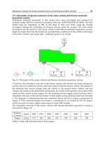
figure 16. Input data into the model are: aerodynamics coefficient of the vehicle and torque
at the drive wheels, and output data – rotational speed at its wheels.
Fig. 16. The model of the motor vehicle with thermo-mechanic propulsion system.
To achieve the simulation network of the motor vehicle with thermo-mechanic propulsion
system, the next models have been used: the model of the heat motor vehicle, the models of
the elements that convey energy from the vehicle to the ground (drive wheels and free
wheels), the model of the differential mechanism, the model of the gearbox, the model of the
clutch and the model of heat engine. For the modeling of heat engine, there has been used a
simulation network of the external feature of heat engine, using technical data from the table
1. The diagram of relationship between rotational speed and drive torque is presented in
Figure 17. This technical feature, from table 1, corresponds to an Andoria 4CT90 TD engine,
which was part of motor vehicle endowment in some ARO models.
The simulation network of the motor vehicle with thermo-mechanic propulsion system is
presented in Figure 18
Rotation
al speed
[rpm] 1000 1500 2000 2500 3000 3500 4000
Torque [Nm] 170 183 186 183 178 168 158
Table 1. Table with technical data of heat engine.
Advances in Mechatronics
90
Fig. 17. External feature of the heat engine.
Fig. 18. The simulation network of the motor vehicle with thermo-mechanic propulsion
system.
Data about the drive module used to define the models of the simulation network:
transmission with 4 speeds (with the next transmission ratios: step I 4.92; step II 2.682; step
III 1.654; step IV 1); mechanical switch box with 2 steps; differentials on the front and back
bridges, with transmission ratios of 3.72:1; diameter of the wheel D = 736 mm; rolling radius
R = 350 mm; cross surface St = 3.57 m
2
; motor vehicle weight: own weight 1680 daN; total
weight 2500 daN; rolling resistance coefficient f = 0.02; ramp angle α = 0
o
; gravitational
acceleration g = 9.81 m/s
2
; aerodynamics resistance coefficient K = 0.0375 daN/m
2
;
efficiency of the transmission η = 0.9.
Mechatronic Systems for Kinetic Energy Recovery at the Braking of Motor Vehicles
91
Simulation network was run under the next conditions: at the input of the heat engine has
been forced a control signal (acceleration pedal), corresponding to the torque/rotational
speed dependence curve in Figure 17. The grafical results ar presented in Figure 19. It was
maintained constant (100%) for a period of 40 seconds, as is shown in Figure 19(a). At the
moment t = 40 s, full closure was ordered to supply no longer the heat engine. The aim of
this simulation was to register the evolution of dynamic parameters of the motor vehicle, in
the stage of running on energy received from the heat engine and during movement due to
inertia of the system, sees Figure 19, namely: the variation over time of control signal of heat
engine (0 1 corresponds to 0 100%), see Figure 19(a), the eevolution over time of displacement of
motor vehicle, see Figure 19(b). Evolution of running velocity of motor vehicle, see Figure
19(c), Evolution over time of acceleration of vehicle, see Figure 19(d), variation of torque at
the heat engine shaft, see Figure 19(e), Variation of rotational speed at the heat engine shaft,
gearbox and differential mechanism, see Figure 19(f).
(a) Variation over time of control signal of heat (b) Evolution over time of displacement of
vehicles
(c) Evolution of running velocity of (d) Evolution over time of acceleration
motor vehicle of vehicles
Advances in Mechatronics
92
(e) Variation of torque at the heat engine shaft (f) Cluch rotary velocity
(g) Variation of rotational speed at the heat engine shaft, gearbox and differential
Fig. 19. Variation of the dynamic parameters of the motor vehicle with thermo-mechanic
propulsion system.
2.4.2 Simulation of dynamic behavior of the motor vehicle with thermo-hydraulic
propulsion hybrid system
The motor vehicle with thermo-mechanic propulsion system has been analyzed with the
simulation network shown in Figure 18. The simulation network of dynamic behavior of the
motor vehicle with thermo-hydraulic propulsion hybrid system includes the simulation
network of thermo-mechanical system, shown in Figure 18, to which was attached the
components of energy recovery hydraulic system, to storage and to use of recovery energy
achieved at the braking of motor vehicle. Hydrostatic component attached to the thermo-
mechanic model is a basic one, greatly simplified for the reason to have an overview of the
simulation network. Full schematic diagram includes a series of other elements of
hydrostatic instrumentation absolutely necessary for the development of such a system. As
it can be seen, in the Figure 20, the most important elements of the hydrostatic system are:
bidirectional and reversible hydrostatic unit, battery of oleopneumatic accumulators and
mechatronic system for control and adjustment of capacity of the hydrostatic unit.
Mechatronic Systems for Kinetic Energy Recovery at the Braking of Motor Vehicles
93
Fig. 20. The simulation network of the dynamic behavior of the motor vehicle with thermo-
hydraulic propulsion system.
Data about the hydrostatic drive module used to define the simulation network are the next:
capacity of the hydrostatic unit: 45 cm
3
; volume of the oleopneumatic accumulators: 25
liters; system which conveys mechanical energy between the hydrostatic unit and gearbox
with transmission ratio: 1:1; density of working oil 850 kg/m
3
; oil elasticity module: 16000
bar; gas pressure inside accumulators: 100 bar. The ssimulation network of the dynamic
behavior of the motor vehicle with thermo-hydraulic propulsion hybrid system has been
similarly to the previously presented network, to determine the evolution of dynamic
parameters of vehicle. The conditions, under which the model has been run, were the next:
-
at the input of the heat engine has been forced a control signal (acceleration pedal)
corresponding to the torque/rotational speed dependence curve in Figure 17. It was
maintained constant (100%) for a period of 40 seconds (Fig. 19a). At moment t = 40 s full
closure was ordered to supply no longer the heat engine.
-
at moment t = 40 s hydrostatic unit was ordered with a control signal corresponding to
its operation in pump mode, with capacity varying after a ramp-step-ramp signal 0
100%, for 10 seconds. During this period the energy recovery function is performed
(loading of oleopneumatic accumulators).
- during time span t1 = 40 seconds t2 = 60 seconds the hydrostatic drive has capacity of 0
cm
3
, the energy recovery system is "decoupled" from the mechanical system.
-
at moment t = 60 s hydrostatic unit was ordered with a control signal corresponding to
its operation in motor mode, with capacity varying after a ramp-step-ramp signal 0
100%, for 20 seconds. During this period the use of recovered energy function is
performed (discharge of oleopneumatic accumulators).
Advances in Mechatronics
94
The graphical results, recorded from simulation process, are shown in Figures 21, where it
can see: the evolution over time of displacement of motor vehicle, in Figure 21(a), the
evolution over time of running velocity of motor vehicle and control signal of hydrostatic
unit, in Figure 21(b), the evolution over time of acceleration of vehicle, in Figure 21(c), the
variation of torque at the heat engine shaft, in Figure 21(d), the variation of force at the drive
wheel, in Figure 21(e), the evolution of pressure inside of accumulators, in Figure 21(f), and,
finally, the evolution of the oil flow inside the accumulators depending on control signal of
the hydrostatic unit capacity, which can be seen in Figure 21(g),
(a) Evolution over time of displacement of
motor vehicle
(b) Evolution over time of running
velocity of motor vehicle and control
signal of hydrostatic unit
(c) Evolution over time of acceleration of
vehicle
(d) Variation of torque at the heat engine
shaft
Mechatronic Systems for Kinetic Energy Recovery at the Braking of Motor Vehicles
95
(e) Variation of force at the drive wheel
(f) Evolution of pressure inside of
accumulators
(g) Evolution of oil flow inside the accumulators depending on control signal of the
hydrostatic unit capacity
Fig. 21. The variation of the dynamic parameters of the motor vehicle with thermo-hydraulic
propulsion system.
3. The mechatronic stand for testing the kinetic energy recovery system
For testing, in laboratory conditions, of the energy recovery mechatronic system, there was
necessary to design and physically develop a test stand, able to reproduce the characteristic
working modes of a hybrid motor vehicle with the ability to recover kinetic energy during
braking. The stand, in itself, is conceived also as one mechatronic system.
The goal of stand design and development was to create the possibility of putting the
developed mechatronic system for kinetic energy recovery under a series of tests, conducted
during all the working modes/stages, before being implemented on a motor vehicle, in
order to understand its dynamic behavior and the genuine abilities of the system, and, also, to
detect early any gaps or shortcomings and new needs, to improve the system on the fly. The
stand, also, allows the development of complex experimental research and minimizes the
Advances in Mechatronics
96
risks borne by a project of this complexity, in case of its direct implementation on the
vehicle, without testing in laboratory conditions, (Cristescu, 2008a).
3.1 The technical solution adopted for designing of test stand
The technical solution adopted, in principle, for design and implementation of the test stand
of mechatronic system for braking energy recovery, was that of simulation, in laboratory
conditions, of the transitional working regimes for starting and braking the motor vehicles,
based on the use of specific equipment only with electric and hydraulic drive and control,
monitoring the evolution of parameters within the system and managing the processes by
computer, using some dedicated software. For simulating the operation of the heat engine of
the motor vehicle, a combined solution was chosen, based on hydraulic electro-pump,
composed of an electric motor and a high pressure hydrostatic pump, which drives a
hydraulic motor (or the acceleration module), together simulating the thermal power, torque
and rotational speed source, parts of the normal equipment of a motor vehicle. The second
source of power, hydraulic power, characteristic to the energy recovery system, is represented
exactly by the hydro-mechanical module of the energy recovery system tested on stand,
composed of a hydraulic machine and the chain or gear transmission, shown in Figure 25
(a). One load module gathers/integrates, on its input, the two powers, simulating thus the
thermo-hydraulic hybrid propulsion system of motor vehicles. In this way, 3 propulsion systems
of the motor vehicle can be simulated on stand:
-
thermo-mechanical propulsion, based on the heat engine of the motor vehicle;
-
mechano-hydraulic propulsion, based on the hydraulic recovery system;
-
thermo-hydraulic hybrid propulsion.
Technical solution adopted allows simulation of braking modes with kinetic energy
recovery system, namely:
-
braking with recovery of kinetic energy impressed by the thermo-mechanical system;
-
braking with recovery of kinetic energy impressed by the hydraulic propulsion system
3.2 The general assembly and the structure of the mechatronic test stand
General assembly of mechatronic stand, designed to test the kinetic energy recovery system,
is shown in Figure 22, and the physical development of the stand is shown in Figures 23 and
Figure 24.
The structure of mechatronic test stand consists of the following modules, which can be seen
in Figure 25:
1.
hydro-mechanical module of the tested mechatronic system for energy recovery, as a
source of hydraulic power of the hybrid drive system, consisting of a hydraulic machine
and a mechanical chain or gear transmission, fitted with a torque and speed transducer,
to monitor the main parameters: torque and speed, shown Figure 25(a);
2.
test module or loading module, comprising a load device, with a frame containing a torque
transducer, having coupled, at its output, a hydraulic unit, and at its input, the hydro-
mechanical module of the enrgy recovery system, subjected to testing, shown in Figure
25(b);
3.
module of the electropump, with variable rotational speed and displacement, which forms
together with the acceleration module (hydraulic motor), the subsystem for simulation
of the drive engine, shown in Figure 25(c);
Mechatronic Systems for Kinetic Energy Recovery at the Braking of Motor Vehicles
97
4. acceleration module, comprising a hydraulic motor, torque and speed transducer, and
cardan shaft that connects mechanically the two drive systems simulated, heat and
hydraulic, shown in Figure 25(d);
5.
module for storage of the fluid under pressure or battery of accumulators, comprising a
supporting frame on which two hydropneumatic accumulators are mounted, as well as
the related security devices, shown in Figure 25(e);
6.
module of the hydraulic station, with working fluid conditioning subsystem, consisting of
an oil tank equipped with temperature control system, drive pump and hydraulic
blocks, shown in Figure 25(f);
7.
electrical, electronic and automation subsystem, with an electrical and electronic subsystem
for actuation and control of stand operation and with a subsystem of sensors and
transducers for monitoring parameters, Figure 25(g);
8.
informatic and control subsystems, for monitoring and control of stand operation, shown
in Figure 25(h);.
The first six modules represent the mechano-hydro-pneumatic subsystem of the test stand,
which, toghether with the electronic subsystem and the informatic and control subsystems,
create a typical structure of one mechatronic system, (Maties, 1998).
The main modules of the mechatronic test stand were presented in Figure 25.
The stand allows to do testing in the field of hydrostatic transmissions, in order to optimize
them functionally and to improve their energy efficiency. The stand is proper for rotary
hydrostatic transmissions, with or without energy recovery systems, which are part of fixed
(industrial) and mobile (towed vehicles and motor vehicles) equipment, including their
subsystems, for functional tests and to establish performance parameters.
Fig. 22. General assembly of the mechatronic stand for testing of the kinetic energy recovery
system.
Advances in Mechatronics
98
Fig. 23. Mechatronic stand for testing the kinetic energy recovery system – overview.
Fig. 24. Mechatronic stand for testing the kinetic energy recovery system – frontal view.
Mechatronic Systems for Kinetic Energy Recovery at the Braking of Motor Vehicles
99
a) The hydro-mechanical module of the
recovery system
b) The testing module
c) Module of the electropump
d) The acceleration subsystem
e) The accumulating subsystem
f) The hydraulic station
Advances in Mechatronics
100
g) The electric and electronic subsystem
h) Informatic and control subsystems
Fig. 25. The main modules of the mechatronic test stand.
3.3 Testing of dynamic behavior of the hybrid motor vehicles by using of the real-time
simulation network
The analyzed system has been studied both by means offered by conventional methods of
mathematical modeling and numerical simulation and, also, by using the hybrid networks
of real-time co-simulation and simulation (Ion Guta, 2008).
In order to testing of dynamic behavior of the hybrid motor vehicles by using of the real-time
simulation network, is necessary to do this in two steps. For developing the real-time
simulation the first step is the creating of the co-simulation subsystem, which will be
presented in the next subchapter. In the second step, it will be used the hybrid simulators,
which connect in terms of information the mathematical models and components of
physical systems
3.3.1 The creating of the co-simulation subsystem
For achieving the co-simulation networks, there have been used the above presented
models, developed by means of AMESim software, (LMS IMAGINE SA, 2009). These were
coupled to a simulation supervisory application, developed by the authors, of this work by
means of LabVIEW programming language, (LabVIEW, 1993). This was a first step for
developing the real-time simulation application presented in the experimental section of this
work. In Figure 26 can be seen the co-simulation subsystem, the process model being
coupled to the application developed in LabVIEW and loaded on a NI PXI industrial
computer, through the communication process implying sharing of memory (shared
memory). For communication between the two systems, there can also be used TCP/IP
sockets or TCP/IP protocol.
Application developed using LabVIEW language, seen in Figure 27(a), has an operator
interface that allows governing of the simulation process and visualization of data obtained
during simulation, Figure 27(b). The application contains an automation component which
controls the hydrostatic equipment within the simulation network, by adjustment of
hydrostatic unit capacity, opening and closing of way directional control valves, comprised
in the hydrostatic subsystem.
Mechatronic Systems for Kinetic Energy Recovery at the Braking of Motor Vehicles
101
Fig. 26. Co-simulation subsystem.
(a) Block diagram of data acquisition module
(b) Interface VI of stand functioning
Fig. 27. The application developed in LabVIEW language.
Advances in Mechatronics
102
3.3.2 Testing energy recovery system by using the hybrid networks of real-time co-
simulation and simulation
The solution adopted to achieve the hydrostatic transmission testing system for the energy
recovery systems, was that of simulation of operating, braking and start-up modes of motor
vehicles, based on electrohydraulic actuation equipment and systems for simulation and
numerical modeling specific to the field of hydrostatic drive. The simulations and the
experiments have been achieved in the laboratory of hydrostatic transmissions of the
institute INOE 2000 – IHP, where. are conducted experimental research in the field of
hydrostatic rotary transmissions, in order to optimize them functionally and improve their
energy efficiency. To know the dynamic behavior of the energy recovery system, in
laboratory conditions, it was used the concept of "real-time simulation" of a system, or
„Harwar-in-the loop” (HIL), involving the simultaneous use of a mathematical model and a
physical part of the system, see (Gauchia & Sanz, 2010).
The introduction of computers in monitoring and control of industrial process, led to change
of technological systems. Great flexibility offered by these systems allows "software"
optimization of complex systems. In this scenario it is rational the use of hybrid simulators,
which connect in terms of information the mathematical models and components of
physical systems. This concept has been established in the specialized literature as "real-time
simulation" or "numerical simulation with control loop equipment". (Ion Guta, 2008). Modern
methods of experimentation, in the field of hydraulic and pneumatic drive systems, imply
the existence of at least one numerical calculation equipment. The necessity of using electro-
hydraulic converters, for control and adjustment of various physical parameters such as
force, displacement, together with the exponential growth of digital electronics, confirms
this. Digital equipment can be found in the structure of sensors and transducers, numerical
displays, electronic servo-amplifiers (compensators) or process computers. As part of the
endowment of any modern laboratory of electro hydraulic drives there are not lacking
sensors and transducers with electronic communication interface, adjustment systems
(proportional electro hydraulic directional control valves, hydraulic or pneumatic servo
pumps/ motors etc.) with analog/digital control ports and electronic adjustment blocks.
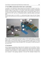
The ability to "load" the numerical calculation systems, with "virtual models" of systems
developed using advanced modeling languages, increases even more their flexibility, as it
can be seen in Figure 28.
The system includes a numerical model simulating the dynamic behavior of a motor vehicle
with thermo-mechanic propulsion, a process computer of PXI (from National Instruments)
family, an experimental stand and a system for regular acquisition of data in the analyzed
process. The purpose of this analysis is to be excited correspondingly, based on specific
input data into the mathematical model, the power components of the experimental stand by
means of the process computer, in order to be quantified the amount of energy that it can
recover under simulated operation conditions.
To perform experiments in the simulation model (Figure 20) has been removed simulation
of the electro hydraulic subsystem. In place of this component, there has been introduced
into the model, information gathered from the testing stand, which contains the physical
component of the electro hydraulic subsystem. The next technological parameters on the
stand have been introduced into the model: rotational speed at the shaft of hydrostatic unit
and torque obtained at the shaft of the unit. From the simulation model, a command has
been sent to the physical unit on the stand, by means of which has been emulated the heat
engine. The command has been sent so, that rotational speed achieved at the shaft of
Mechatronic Systems for Kinetic Energy Recovery at the Braking of Motor Vehicles
103
Fig. 28. The hibride network of real-time simulation for testing energy recovery system, in
laboratory conditions.
hydraulic motor (which emulates, on the testing stand, the real heat engine) to be dependent
on its torque, according to the torque/rotational speed functional curve imposed in the
simulation model. Adjustment of rotational speed at the drive shaft has been performed by
appropriate variation of the hydrostatic unit capacity. In parallel, computer component of
the mechatronic stand, for recovery of braking energy of a motor vehicle, has controlled the
devices on the stand so that the simulation model on the PXI industrial computer to record
the next cyclogram:
-
drive of clutch (coupling of the heat engine to the motor vehicle gearbox) at t = 0
seconds;
- drive of gearbox accordingly to speed step 1 at t = 0 seconds;
-
drive of acceleration of the engine till achieving a running velocity of the vehicle of 10
m/s at t = 0 30 seconds;
- drive of clutch (decoupling of the heat engine from the motor vehicle inertial load) at t =
30 70 seconds;
- drive of hydrostatic unit capacity of the energy recovery system, corresponding to its
operation in pump mode (working with energy recovery) at t = 32 50 seconds;
-
free operation till the motor vehicle stops;
-
drive of clutch (coupling of the heat engine to the motor vehicle gearbox) at t = 70
seconds;
- drive of gearbox accordingly to speed step 1 at t = 70 seconds;
-
drive of engine acceleration simultaneously with drive of capacity of the system
hydrostatic unit corresponding to its operation in motor mode (use of hydrostatic
power available in the mechatronic recovery system) till achieving a running velocity of
the motor vehicle of 10 m/s at t = 70 seconds;
Advances in Mechatronics
104
- drive of clutch (decoupling of the heat engine from the motor vehicle inertial load) at t =
100 seconds;
-
drive of hydrostatic unit capacity of the energy recovery system corresponding to its
operation in pump mode (working with energy recovery) at t = 105 118 seconds;
- free operation till the motor vehicle stops.
Data obtained from experiments of real-time simulation for testing of energy recovery
system are shown in Figures 29, where it can see the evolution over time of displacement of
motor vehicle, in Figures 29(a), the evolution over time of running velocity of motor vehicle,
in Figures 29(b), the vvariation of torque at the shaft of the system equivalent to a heat
engine and at the shaft of the hydrostatic unit, in Figures 29(c), the evolution over time of
acceleration of motor vehicle, in Figures 29(d). Finally, the comparative study on the
evolution of torque at the drive shaft, with and without contribution of mechatronic system
for energy recovery in the braking phase ,is presented in Figures 30.
(a) Evolution of displacement of motor
vehicle
(b) Evolution of running velocity of motor
vehicle
(c) Variation of torque at the shaft of the
system equivalent to a heat engine and at the
shaft of the hydrostatic unit
(d) Evolution over time of acceleration of
motor vehicle
Fig. 29. Data obtained from experiments of real-time simulation for testing of energy
recovery system.
Mechatronic Systems for Kinetic Energy Recovery at the Braking of Motor Vehicles
105
Fig. 30. Comparative study on the evolution of torque at the drive shaft with and without
contribution of mechatronic system for recovery of the motor vehicle braking energy.
4. Conclusions
Given the necessity of finding alternative solution to reduce consumption of fossil
combustible, being now in exhaustion, and to mitigate the negative impact of emission on
the environment, vehicle manufacturers have indicated that an effective solution, could be
the development of hybrid propulsion systems, in particular those regenerative propulsion
systems, which can recover a portion of the kinetic energy of the vehicle, accumulated
before braking.
In this context, the chapter presents some specific problems concerning the complexity of
the hybrid propulsion systems of the road vehicles and points out that, indeed, this is a new
area suitable for the application of mechatronics, where it is the only technology able to
monitor, to manage and to optimize the transient regimes specific for this systems.
By addressing the problem of recovering kinetic energy, when road vehicles are at braking,
the authors have reached automatically and at the issue of the hybrid propulsion systems,
and they gained o good theoretical and practical experience, which is communicate in this
chapter and which can be a point start-up for other researches.
In the first part, the paper presents the general problem of the energy recovery systems and
makes a brief presentation for one Romanian mechatronic hydraulic system for energy
Advances in Mechatronics
106
recovery, which transforms one motor vehicle, where it is implemented, into motor vehicle
with hybrid propulsion system, including the main modules of the system.
There are presented some theoretical results obtained by mathematical modeling and
numerical simulations, in frame of a preliminary research, which allowed to be chosen some
basic components of mechatronic system of energy recovery.
The complexity of issues required by a hybrid propulsion system with energy recovery,
have imposed, on the one hand, the choice of mechatronic technology like modality to
conceive and to design and, on the other hand, has led to designing and manufacturing of a
stand for testing of kinetic energy recovery system, stand which is presented in the second
part of the chapter. Also, are presented some graphical results obtained by real-time
simulation, this new research technology used and by others researchers, which involves the
simultaneous use of a mathematical model and a physical part of the studied system. The
obtained graphical results confirm, generally, the preliminary theoretical results.
The chapter presents and demonstrates the possibility to design, manufacturing and
implementing the energy recovery systems on medium and heavy road motor vehicles, in
order to increasing the energy efficiency. The solution allows the extrapolation to different
sizes of vehicles and can be mounted on new motor vehicles, as well as on old cars, in the
framework of a rehabilitation.The hydraulic and electric necessary components are available
on the market
Also, the chapter demonstrates that the only technology which can control and monitories
the energy recovery systems, especially the hibrid propulsion systems, is the mechatronics
technology.
5. Acknowledgement
This chapter presents some results obtained on a research project conducted under the
Romanian Excellence Research Program and funded by National Authority for Scientific
Research-ANCS from Romania.
6. References
Adelt, Ph., Esau, Nat., Hölscher Ch., Kleinjohann B. Kleinjohann L., Krüger M. & Zimmer
D. (2011). Hybrid Planning for Self-Optimization in Railbound Mechatronic
Systems, In: Intelligent Mechatronics, Ganesh Naik (Ed.), pp. 169-194, ISBN: 978-953-
307-300-2, InTech, Available from:
/>optimization-in-railbound-mechatronic-systems
Ardeleanu, M., Gheorghe, Gh. & Matei, Gh. (2007). Mecatronics. Principles and Applications,
Publishing House AGIR, ISBN: 973-720-142-3, Bucharest, Romania
Bosch Rexroth Group, Hydraulic Hybrids from Rexroth: Hydrostatic Regenerative Braking System
HRB, Available from:
/>pany/Press/trade_show_information/a_downloads/Hydrostatic_Regenerative_Br
aking_Brochure.pdf and www.boschrexroth.com
Calinoiu, C., Vasiliu, N. & Vasiliu, D. (1998). Modeling, Simulation and experimental
Identification of the Hydraulic Servomechanisms Technical Publishing House, ISBN
973-31-1315-8, Bucharest, Romania
Mechatronic Systems for Kinetic Energy Recovery at the Braking of Motor Vehicles
107
Cristescu, C. (2008), The recovery of kinetic energy at braking of motor vehicle, Publishing House
AGIR, ISBN 978-973-720-219-2, Bucharest, Romania
Cristescu, C., Drumea, P., Ilie, I., Blejan, M. & Dutu, I. (2008). Mechatronics system for
recovering braking energy conceived for the medium and heavy motor vehicles,
Abstract Proceedings of The 31th International Spring Seminar on Electronics.
Technology-Reability and Life Time Prediction, pp. 192-193, ISBN 978-963-06-4915-8,
Budapest, Hungary, 7-11 May, 2008. . ,
www.ett.bme.hu/isse/isse2008/
Drumea, P.; Popescu, T.C.; Blejan, M. & Rotaru, D. (2010). Research Activities Regarding
Secondary and Primary Adjustment in Fluid Power Systems, 7th International Fluid
Power Conference Aachen Efficiency through Fluid Power, Scientific Poster Session,
Aachen, Germany, 22-24 March 2010,
Eaton (2011). Electric Hybrid Available from
/>rid/index.htm
Eaton (2011). Hydraulic Hybrid, Available from:
/>ower/SystemsOverview/HydraulicHybrid/index.htm and
www.eaton.com
Gauchia, L. & Sanz J. (2010). Dynamic Modeling and Simulation of Electrochemical Energy
Systems for Electric Vehicles, In: Urban Transport and Hybrid Vehicles, Seref Soylu
(Ed.), pp. 127-150, ISBN: 978-953-307-100-8, Sciyo, Available from:
/>simulation-of- electrochemical-energy-systems-for-electric-vehicles
Ion Guta Dr., Vasiliu, N., Vasiliu, D. , & Calinoiu C. (2008) Basic concepts of real-time
simulation (RTS), U.P.B. Scientific Bulletin, series D: Mechanical Engineering, Vol.
70/2008, No.4, pp. 291-301, ISSN 1457-2358
LabVIEW (1993). Basics Course Manual. National Instruments Corp., Austin, SUA
LMS IMAGINE SA (2009). Advanced Modelling And Simulation Environment, Release 8.2.b.,
User Manual, Roanne, France
Maties, V. (1998). Mechatronics. Publishing House Dacia, Cluj-Napoca, Romania
Math Works Inc. (2007). Simulink R5, Natick, MA, U.S.A
Permo-Drive (2009). What is the Regenerative Drive System (RDS
TM
)? Available
from: www.permo-drive.com and
htm
Parker Hannifin (2010). Fluid power: Saving Energy with Efficient Fluid Power /Hydraulic
Hybrid Drive System, Available from:
www.parker.com and
Popescu, T. C., Vasiliu, D. &Vasiliu N. (2011). Numerical Simulation - a Design Tool for Electro
Hydraulic Servo Systems, Numerical Simulations - Applications, Examples and Theory,
Lutz Angermann (Ed.), ISBN: 978-953-307-440-5, InTech, Available from:
/>tool-for-electro-hydraulic-servo-systems/
Advances in Mechatronics
108
Toyota Prius Hybrid (2008) Available from:
Untaru, M., Cîmpian, V., Hilohi, C. & Vărzescu, V. (1974). Construction and calculation of
automotive (Construcţia şi calculul automobilelor) Technical Publishing House,
Bucharest, Romania