Evapotranspiration covers for landfills and waste sites - Chapter 3 pdf
Bạn đang xem bản rút gọn của tài liệu. Xem và tải ngay bản đầy đủ của tài liệu tại đây (539.49 KB, 19 trang )
15
3
Conventional and
Alternative Covers
This chapter describes the properties of landll covers that are in widespread
use and alternatives to these conventional covers. An important part of this
chapter is a summary of performance measurements for landll covers; they
provide guidance regarding allowable leakage through landll covers.
3.1 CONVENTIONAL LANDFILL COVERS
Most landll covers in place today are conventional, barrier covers because both
state and federal regulatory ofcials have readily accepted them in the past. They
include one or more barrier layers within the cover and they meet the presumptive
requirements for containment. The intention is that the barrier should oppose the
forces of nature and prevent water from moving downward in response to the force
of gravity. A common misconception is that the barrier layers are “impermeable”;
this is seldom, if ever, true. The goal is that the conventional, barrier landll cover
should provide protection for decades or centuries; however, they have actually been
tested for a fraction of their intended life.
This chapter provides an overview of barrier covers. Several authors provide in-
depth discussion of conventional landll covers (US EPA 1991, 1993, 1996; McBean
et al. 1995; Ankeny et al. 1997; Koerner and Daniel 1997; Gill et al. 1999; Weand
et al. 1999).
3.1.1 rcra Su b t I t l e c, ba r r I e r co v e r
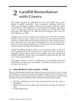
Conventional RCRA Subtitle C covers employ barrier technology and typically
include ve or more layers above the waste (Figure 3.1; US EPA 1991; Koerner and
Daniel 1997). The top layer consists of cover soil that supports a grass cover to pro-
vide wind and water erosion control. The second layer is a drainage layer; its purpose
is to remove water that accumulates above the barrier layer. The barrier layer consists
of either a single low-permeability barrier or two or more barriers in combination.
The gas collection layer permits removal and safe disposal of gas trapped under the
barrier. The foundation layer of variable thickness separates the waste from the cover
and establishes the surface slope.
3.1.1.1 The Cover Soil Layer
The primary function of the surface layer is to control wind and water erosion by
supporting an adequate vegetative cover, and to protect the other layers. The soil
should have adequate physical and chemical properties to store sufcient water for
plant use and to provide the necessary nutrients for plant growth.
© 2009 by Taylor & Francis Group, LLC
16 Evapotranspiration Covers for Landfills and Waste Sites
The cover soil layer is usually about
0.6 m (24 in.) thick; the required thickness
depends on the climate, soil properties, and
vegetation type. In cold climates, the cover
soil may be thicker to protect the barrier
layer from freezing.
The specic requirements at a site may
necessitate additional components in the
cover soil layer. For example, a surface sub-
layer containing a gravel and soil mixture
may control wind erosion in desert regions,
or a layer of cobble-size stone placed near
the bottom of the cover soil layer may pre-
vent animal intrusion into the waste.
3.1.1.2 The Drainage Layer
The cover soil does not stop all precipita-
tion; consequently, precipitation passes
through it into the drainage layer. A drain-
age layer built of highly permeable material should quickly remove water that passes
through the cover soil. Rapid drainage removes the hydraulic head on the underlying
barrier layer, thus reducing inltration through the barrier. Drainage also improves
slope stability by reducing pore water pressure in the layers above the barrier. The
most common materials used for the drainage layer are sand, gravel, and manmade
geosynthetic materials. An effective drainage layer is a required component of a
barrier cover.
3.1.1.3 The Barrier Layer
The barrier layer is the central element of landll covers using barrier technology.
The barrier layer may be a single material or a combination of two or more. The
barrier minimizes percolation of water from the overlying layers into the waste by
opposing the natural ow of water downward in response to gravity.
Compacted clay layers (CCLs) are the most commonly used barrier layers;
they are typically about 0.6 m (24
in.) thick. Federal regulations require a saturated
hydraulic conductivity (K) that is equal to or less than 1 × 10
−7
cm/s. Normally,
CCLs contain naturally clay-rich soils; both desiccation and freezing can greatly
increase the K value of clay barriers.
Other materials are used as barrier layers. Geosynthetic clay layers (GCLs) are
manufactured rolls of bentonite clay held between geotextiles or bonded to a geo-
membrane (GM). The K value of most sodium bentonite GCLs is near 1 × 10
−9
cm/s.
GMs used as barrier layers in landll covers are called exible membrane covers
(FMCs). The most common materials for FMCs in nal covers include high- density
polyethylene (HDPE), linear low-density polyethylene (LLDPE), polypropylene
(PP), and polyvinyl chloride (PVC).
Precipitation
Cover Soil
Drainage
Barrier
Gas Collection
Foundation
Waste
FIGURE 3.1 Cross section of a conven-
tional RCRA landll cover.
© 2009 by Taylor & Francis Group, LLC
Conventional and Alternative Covers 17
Barrier layers incorporating two barriers are normally more effective than a sin-
gle barrier. A typical “composite” barrier includes a GM on top of CCL or a GCL.
3.1.1.4 The Gas Collection Layer
The decomposition of wastes and evaporation of organic compounds within a land-
ll produces gases, some of which are toxic, corrosive, or ammable. Aerobic bio-
logical processes occur when oxygen is available to the waste, generally immediately
after its disposal and produce mostly carbon dioxide. After oxygen depletion in the
waste zone, anaerobic bacteria become dominant and waste decay produces both
carbon dioxide and methane gas along with lesser amounts of hydrogen sulde,
nitrogen, and hydrogen. In addition, volatile organic compounds (VOCs) contained
in the deposited waste or produced by chemical reactions within the waste may be
present in landll gas.
The presence of explosive or toxic gases underground presents a potential problem
to nearby buildings and to personnel working near the landll. Gases follow preferen-
tial ow paths both upward and laterally and either ultimately vent to the atmosphere
or accumulate under natural or articial barrier layers. Collection and disposal of the
gas generated under the cover utilizes either active or passive systems. Any cover that
employs a barrier layer is likely to need a gas control system because the barrier will
probably trap and accumulate explosive or poisonous gas below the cover.
3.1.1.5 The Foundation Layer
The foundation layer establishes the desired surface slope and separates the waste
from the cover. Use the least expensive locally available material that will provide a
stable working surface above the waste.
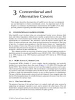
3.1.2 rcra Su b t I t l e d, ba r r I e r co v e r
RCRA Subtitle D covers are modied bar-
rier-type covers (Figure 3.2); an alternate
name for them is compacted-soil, barrier
covers. From the surface downward, these
covers include a grass cover; topsoil layer;
soil compacted to yield a K value of 1 ×
10
−5
cm/s, and a foundation layer above the
waste. Usually, soil found at the site is com-
pacted to form the barrier. The subtitle D
cover meets the federal criteria for Munici-
pal Solid Waste Landlls, 40 CFR, Part
258.60, Closure Criteria; it is suitable for
dry climates. It is a barrier cover because
it relies on compaction to create a layer of
soil with reduced hydraulic conductivity.
However, the topsoil layer is often no more
Topsoil
Barrier
Foundation
Waste
Precipitation
FIGURE 3.2 Cross section of a conven-
tional subtitle D landll cover.
© 2009 by Taylor & Francis Group, LLC
18 Evapotranspiration Covers for Landfills and Waste Sites
than 0.15 m (6 in.) thick. Freezing, drying, or root intrusion into the barrier layer may
increase its hydraulic conductivity (K) and change the covers’ performance.
3.2 ALTERNATIVE BARRIERS FOR COVERS
The alternative barriers discussed in this section are new approaches for design-
ing barrier layers and not complete cover systems. They are at this time primarily
experimental systems.
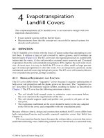
3.2.1 ca P I l l a r y ba r r I e r
The capillary barrier is an alternative to conventional-barrier layers. The capillary
barrier (Figure 3.3) utilizes two layers: a layer of ne soil over a layer of coarser
material (e.g., sand or gravel). A geotextile over the coarse layer will control intru-
sion of nes into the coarse layer. The barrier is the discontinuity in soil pore size
found at the interface between the coarse and ne soil. Capillary force causes the
layer of ne soil overlying the coarser material to hold more water than if there were
no change in pore size between the layers. Lateral drainage, evaporation, and plant
transpiration remove water stored in the soil above the barrier. Stormont (1997), Gee
and Ward (1997), Nyhan et al. (1990), Breshears et al. (2005), and Ankeny et al.
(1997) tested it in experimental installations. A plant cover to remove water stored in
the ne soil is part of a capillary-barrier cover.
A capillary barrier is effective if the combined effect of ET, soil water storage,
and lateral diversion exceeds the inltration from precipitation, thereby keeping the
system sufciently dry so that breakthrough does not occur. This barrier can fail if
too much water accumulates in the ne-soil layer or if the desired large change in
pore size is missing in spots. Experimental
eld systems failed although they allowed
less inltration than a ne soil cover alone
(Nyhan et al. 1990; Nyhan et al. 1997; War-
ren et al. 1996). Gee and Ward (1997) tested
a full-scale capillary-break cover having 2 m
of loose high-quality soil above the interface
and found no leakage during a 2 year period
in an arid climate.
By placing the interface between the soil
and gravel on an incline, lateral ow at pres-
sures less than atmospheric can occur. Stor-
mont (1996) found that alternating ne and
coarse layers were effective over lateral dis-
tances of 7
m (23 ft) on a 10% slope. He also
found that a single capillary-barrier layer
failed under the conditions of his tests.
The capillary-barrier system may be
better than conventional clay hydraulic bar-
riers because it is not subject to desiccation
Fine Soil Cover
Coarse Layer
Foundation
Waste
Geotextile
Other Layers
if Needed
Precipitation
FIGURE 3.3 The capillary barrier
in a landll cover.
© 2009 by Taylor & Francis Group, LLC
Conventional and Alternative Covers 19
and cracking. It may be preferred where soils with high water-holding capacity are
unavailable or expensive and in dry climates.
3.2.1.1 Capillary Barriers without Vegetation
Nyhan et al. (1997) and Nyhan (2005) described an interesting experiment in which
the soil surface remained bare; therefore, evaporation alone removed water from the
soil prole. Because evaporation is smaller than plant transpiration and effectively
removes water from a relatively shallow soil depth, this arrangement placed great
stress on the capillary barrier. Nyhan (2005) incorrectly labeled the cover the “evapo-
transpiration” cover. Because there is no transpiration, they are more correctly called
evaporation covers.
With thick soil covers and 15 or 25% surface slope, no water percolated through
these covers as deep percolation. With thin soil covers and slopes as at as 5%, up to
10% of the precipitation appeared as deep percolation below the cover. Seven years
of measurement demonstrated less average deep percolation than the 3.7-year mea-
surement period (Nyhan et al. 1997; Nyhan 2005).
The research plots were located at Los Alamos, New Mexico, in a dry climate.
The aridity of the climate and high potential evaporation rate probably contributed
to their qualied success.
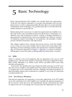
3.2.1.2 Dry Barrier
As illustrated in Figure 3.4, the dry barrier, sometimes called the convective air-
dried barrier, is similar to the capillary barrier except that wind-convective or
power-driven airow through the layer of coarse material helps remove water that
may inltrate into that layer (Ankeny et al. 1997). Dry barriers may be suitable for
landlls in hot, arid climates where capillary
barriers alone may fail.
3.2.2 aS P h a l t ba r r I e r
In arid climates, clay barriers are likely to fail
because of desiccation. Gee and Ward (1997)
demonstrated that asphalt barriers may replace
compacted clay in landll covers. Levitt et al.
(2005) reported the failure of an asphalt cap
placed on the surface over waste material in a
dry climate. Substantial amounts of water moved
through the cover over 37 years. The asphalt cap
was cracked; in addition, a collapsed area and
adverse slopes collected water on the surface of
the cap.
Because oxygen, ultraviolet radiation, and
frost heave damage asphalt, asphalt barriers
should be protected with soil cover as demon-
strated by Gee and Ward (1997). It is important
to ensure adequate drainage from the surface.
Fine Soil Cover
Coarse Layer
Foundation
Waste
Geotextile
Other Layers
if Needed
Air Flow
Precipitation
FIGURE 3.4 The dry barrier in
a landll cover.
© 2009 by Taylor & Francis Group, LLC
20 Evapotranspiration Covers for Landfills and Waste Sites
3.3 ALTERNATIVE COVERS
Because of the water-holding properties of soils and the fact that most precipitation
returns to the atmosphere via ET, a reliable and natural process, it is possible to
devise landll covers that meet the requirements for remediation without a barrier
layer. These covers usually employ a layer of soil on top of the landll where grass,
shrubs, or trees grow for the purpose of controlling erosion and removing water from
the soil water reservoir. They utilize the natural soil water reservoir to temporarily
store inltrating rainfall in the soil until ET removes it.
3.3.1 th e mSr co v e r
Schulz et al. (1997) tested a cover described herein as the modied surface runoff
(MSR) cover for discussion purposes in this book (Figure 3.5). The soil was ne
textured and suitable for plant growth. Panels or “rain gutters” diverted part of the
rainfall off the plot; they planted Pzer juni-
pers between the panels as plant cover. Their
MSR cover was successful.
Karr et al. (1999) reported the results of
a 21-month evaluation of the MSR cover in
Hawaii ending in March 1998. All of their
treatments, including a standard RCRA cover,
allowed deep percolation below the cover.
At least two adverse conditions affected the
results: (1) the treatment designed to divert
40% of precipitation actually diverted only
22% to surface runoff; and (2) the soil in all
plots was compacted to 95% of “optimum”
Proctor density.
Soil density equal to 95% of “optimum”
increases soil strength and signicantly
reduces root growth. High soil density
destroys the large soil pores, which results
in reduced water-holding capacity and severely limits oxygen movement through the
soil when wet. Low soil oxygen may also substantially reduce root growth. The effect
of high soil density is more severe for a ne- than a coarse-textured soil because the
soil pores in a compacted, ne-textured soil are smaller. These factors (explained in
Chapter 5) may have substantially reduced the effectiveness of the MSR cover tested
in Hawaii.
Chittaranjan (2005) reported results of additional study of the MSR experiment
reported by Karr et al. (1999). His measurements began in 1999, and he found that veg-
etation reduced the effectiveness of the rain gutters used to divert rainfall as runoff.
3.3.2 ve g e t a t I v e co v e r S
These covers employ a layer of soil on top of the landll on which grass, shrubs,
or trees grow to control soil erosion and percolation of precipitation into the waste
Foundation
Waste
Cover Soil
Precipitation
FIGURE 3.5 Modied surface runoff
cover.
© 2009 by Taylor & Francis Group, LLC
Conventional and Alternative Covers 21
(Figure 3.6). The soil serves as a reservoir to store
precipitation until the natural process of ET can
remove it (Anderson 1997). The soil in a typical
“vegetative” cover is compacted, which may sig-
nicantly reduce root growth (Chapter 5) and as
a result causes excessive deep percolation through
the cover.
3.3.3 In f I l t r a t e –St a b I l I z e –
e
v a P o t r a n S P I r e co v e r
Blight (2006) dened the “inltrate–stabilize–
evapotranspire” (ISE) landll cover and presented
performance measurements during an 18-month
period. He dened the ISE cover as a layer of com-
pacted soil over the waste and having no vegetation
on the surface. He proposed the ISE cover for use
in water decit areas where annual evaporation exceeded precipitation; he stated that
such areas covered about 65% of the Earth’s surface. A primary objective for the ISE
cover is to promote waste decay and stabilization in dry climates; thus, the goal is to
wet the waste with percolating precipitation.
Because it has no vegetated cover, water is removed from the compacted soil
and the underlying waste by evaporation only. The absence of vegetated cover will
require expensive control measures and regular maintenance to prevent soil erosion
by wind and water.
3.4 PERFORMANCE OF BARRIER COVERS
Successful design and management of waste containment structures require knowl-
edge of the true performance characteristics of each part of the system. Although
barrier layers are sometimes referred to as “impermeable,” in practice this is seldom,
if ever, true.
Table 3.1 contains performance measurements for conventional-barrier landll
covers, including compacted soil, compacted clay, “US EPA” barrier cover with bare
soil, and composite-barrier covers. The data are arbitrarily divided into two groups:
arid (less than 300 mm annual precipitation) and other or wetter sites. The test with
longest duration measured performance for 14 years and the shortest included a
single year of measurements. Short records, and particularly those with less than
a 3-year duration, do not adequately sample the climate at the site; however, they
provide other useful information about landll cover performance.
3.4.1 co m P a c t e d So I l
Compacted soil covers are the simplest and least expensive conventional covers; a
common name for them is the subtitle D cover (Figure 3.2). The regulations in the
United States specify a maximum saturated hydraulic conductivity of 1 × 10
−5
cm/s
Foundation
Waste
Cover Soil
(Usually Compacted)
Precipitation
FIGURE 3.6 Cross section of a
vegetative cover.
© 2009 by Taylor & Francis Group, LLC
22 Evapotranspiration Covers for Landfills and Waste Sites
TABLE 3.1
Measured Performance of Barrier Landfill Covers Utilizing Compacted
Soil, Compacted Clay, and Composite Barriers
Reference Location
Test
Duration
(year)
a
Average Annual
Precipitation
(mm)
b
Leakage
(mm) (%)
c
Compacted-Soil, Barrier Cover
Dwyer 2001 Albuquerque, NM 3.0 247 5 2
Albright et al. 2004 Altamont, CA 2.0 343 2 1
Warren et al. 1996 Hill AFB, UT 3.8 539 109 20
Albright et al. 2004 Albany, GA 3.0 1191 118 10
Compacted-Clay, Barrier Cover
Albright et al. 2006b Apple Valley, CA 2.9 188 8 4
Warren et al. 1996 Hill AFB, UT 3.8 539 Trace Trace
d
Albright et al. 2006b Cedar Rapids, IA 4.0 815 72 9
Melchior 1997, 20% slope Hamburg, DE 8.0 865 65 8
Melchior 1997, 4% slope Hamburg, DE 8.0 865 81 9
Albright et al. 2006a Albany, GA 2.25 1056 267 25
“US EPA” Barrier Cover with Bare Soil Surface
e
Nyhan et al. 1997 Los Alamos, NM 3.7 462 0 0
Composite-Barrier Cover
Albright et al. 2004 Boardman, OR 2.0 130 0 0
Albright et al. 2004 Apple Valley, CA 1.0 148 0 0
Dwyer 2001 (GM/CL) Albuquerque, NM 3.0 247 <1 <1
Dwyer 2001 (GM/GCL) Albuquerque, NM 3.0 247 2 1
Albright et al. 2004 Polson, MT 3.0 311 <1 <1
Albright et al. 2004 Marina, CA 3.0 322 23 7
Albright et al. 2004 Altamont, CA 2.0 343 2 1
Albright et al. 2004 Omaha, NE 2.0 518 5 1
Albright et al. 2004 Cedar Rapids, IA 1.0 791 21 3
Melchior 1997, 20% slope Hamburg, DE 8.0 865 1 <1
Melchior 1997, 4% slope Hamburg, DE 8.0 865 1 <1
Melchior 1997, 4% slope Hamburg, DE 8.0 865 4 <1
Loehr and Haikola 2003 Northeastern
United States
14.0 1320 26 2
a
Measurements for full years are shown when available.
b
Annual precipitation includes irrigation, if any.
c
Leakage rate expressed as percentage of annual precipitation.
d
Clay became progressively wetter and was saturated at the end of the test.
e
Compacted, clay–tuff mixture with low permeability; no vegetation on surface.
© 2009 by Taylor & Francis Group, LLC
Conventional and Alternative Covers 23
for barrier soil in these covers (US EPA 1991,1996). That rate would allow 315 mm/
year of deep percolation if the barrier layer were continuously wetted with a hydrau-
lic gradient of 1. Subtitle D covers are widely accepted for use as nal landll covers
in arid and semiarid locations.
In an arid climate, Dwyer (2001) placed 150 mm of topsoil over 450 mm of com-
pacted native soil. He measured percolation equal to 2% of precipitation during a
3-year period. In the near-desert climate of Albuquerque, New Mexico, evaporation
from the soil surface should remove most precipitation from the soil within a week
or less. This compacted soil cover leaked a surprising amount given the near-desert
conditions and low precipitation at the site.
Albright et al. (2004) measured percolation rates, for 2 or 3 years, through two
covers that were similar to subtitle D covers. At Altamont, California, a dry site, the
cover was about 380 mm of clay soil over a 600-mm-thick CCL; the average percola-
tion for 2 years at that dry site was less than 1% of annual precipitation. At Albany,
Georgia, a wet site, the cover was about 600 mm of soil over 700 mm of compacted
clayey sand; the average percolation for 3 years was 10% of annual precipitation.
At a semiarid site, Warren et al. (1996) used a single layer of compacted topsoil
900 mm deep; they measured 20% of rainfall as deep percolation. The soil was
compacted at all of these sites, but the soil at Warren’s site was compacted to a high
density (1.86 Mg/m
3
) and it leaked a surprising amount in that dry climate.
Benson et al. (2007) reported changes in compacted soils similar to subtitle D
covers at 10 sites. The climate at these sites varied from hot, dry desert to humid and
cold. The resulting as-built hydraulic conductivities (K) varied from 8.6 × 10
−8
to
3.1 × 10
−5
cm/s for the various soils used. After 2 to 4 years of service, the K value of
the compacted soils increased to 10
−5
to 10
−3
cm/s. The K value for some increased
by a factor of 10,000.
The compacted-soil, barrier cover allowed substantial leakage, in wet or dry
climates; it has four deciencies:
The topsoil layer has limited water-holding capacity because it is thin.•
There is no drainage layer.•
Few roots penetrate the compacted soil mass between cracks, thus limiting •
extraction of water from the compacted barrier layer.
Soil freezing and drying, and other factors, increase the K value of the bar-•
rier soil up to 10,000 times its as-built value.
3.4.2 co m P a c t e d cl a y
The term compacted clay here denes an RCRA cover with a single compacted clay
barrier layer and a drainage layer (Figure 3.1).
The regulations specify a maximum saturated hydraulic conductivity of 1 ×
10
−7
cm/s for clay barriers (US EPA 1991,1993); that rate allows 32 mm/year of deep
percolation, if the barrier is continuously wetted with a hydraulic gradient of 1. The
liners under landll waste were the rst application of compacted clay barriers. In
that environment, they are generally successful because they tend to remain wet, are
under constant compacting pressure, and seldom if ever freeze. However, similar
© 2009 by Taylor & Francis Group, LLC
24 Evapotranspiration Covers for Landfills and Waste Sites
compacted clay barriers used in landll covers may dry, and they are subject to
freezing, or to plant root activity. These factors render clay barriers less effective
when used in covers. Suter et al. (1993) reviewed failure mechanisms for compacted
soil covers in landlls; they concluded that “natural physical and biological pro-
cesses can be expected to cause [clay] barriers to fail in the long term.” Table 3.1
contains measurements of deep percolation through six experimental compacted
clay-barrier covers.
The precipitation at Apple Valley, California, was typical of desert climate
(Table 3.1). Because evaporation exceeds the measured precipitation at that site, the
leakage into the waste of 4% of precipitation is not expected.
Warren et al. (1996) reported only a trace of leakage in a semiarid climate; how-
ever, they noted that the soil water content of the clay barrier after 3.8 years was
at the saturation value and increasing. Melchior (1997) reported that in a cool, wet
climate clay barriers leaked 8 or 9% of precipitation; he noted that at the end of an
8 year experiment, leakage rates were increasing.
Albright et al. (2006a) measured the performance of a compacted clay-barrier
cover in southern Georgia; the climate is subtropical and wet. After 4 years of ser-
vice, they observed numerous cracks in the clay barrier and roots growing in the
cracks. Leakage through the cover was small prior to a short drought during the rst
year of service, but increased substantially after the drought. The authors concluded
that soil drying during the drought created the dense network of soil cracks. Leak-
age through the cover was increasing at the end of the test. The measured increase in
hydraulic conductivity was from 10
−7
to 10
−4
cm/s during the short service life.
Albright et al. (2006b) measured performance of compacted clay-barrier covers
at three sites during 2 to 4 years. The climate at the sites was desert in California,
humid in Iowa, and subtropical, wet in Georgia. The as-built hydraulic conductivity
of the clay barrier layers varied between 1.6 × 10
−8
and 4.0 × 10
−8
cm/s. During the
short test period, the hydraulic conductivity of the barriers increased between 106
and 765 times the as-built value. In addition to these three sites, the authors cited
measurements at four other locations. They concluded that “large increases in the
hydraulic conductivity of clay barriers with time are not uncommon.”
Some of the experimental measurements of performance for compacted clay-
barrier covers were too short to demonstrate their probable long-term performance.
However, all of them allowed annual leakage varying between trace amounts and
25% of annual precipitation. The compacted clay-barrier covers leaked in both des-
ert and wet climates. Even though they are prone to leak, compacted-clay barriers
have been widely accepted for use as nal landll covers.
3.4.3 “uS ePa” ba r r I e r co v e r W I t h ba r e So I l Su r f a c e
Nyhan et al. (1997) tested an interesting concept. Even though the sum of evapora-
tion from the soil and plant transpiration is substantially larger than evaporation
alone, they built a barrier cover without plants on the surface. They compacted a
mixture of clay and crushed tuff to create the barrier layer in a cover that resembled
an EPA-dened RCRA cover. During their 3.7 year test period, it allowed no deep
percolation, presumably because the barrier functioned as intended (Table 3.1). They
© 2009 by Taylor & Francis Group, LLC
Conventional and Alternative Covers 25
did not report the reason for the good performance. One may speculate that the good
performance resulted from a superior mix of materials in the barrier or from less
drying of the barrier layer because there were no plants on the surface. Less dry-
ing of the compacted barrier should substantially reduce the amount of barrier-layer
cracking and serve to maintain its desired low hydraulic conductivity.
3.4.4 ge o m e m b r a n e ba r r I e r S
Geomembrane (GM) barriers are also prone to leak. Board and Laine (1995) found
26 holes in the GM of a 1.6 ha (4 acres) liner. Crozier and Walker (1995) examined
seven GM installations and found holes ranging in size from pinholes to 2 m gashes;
the average number was ve per hectare (two per acre). They traced most leaks in
GMs to holes left by construction; however, they did not measure leakage rate.
3.4.5 co m P o S I t e ba r r I e r S
Composite barriers, for example compacted clay covered by a GM (Figure 3.1), are
accepted as the best barrier covers. They are costly to build; however, they performed
better than the single barriers tested in this group of experiments (Table 3.1).
The composite-barrier covers at the two driest sites produced no leakage; how-
ever, the test duration was only 1 or 2 years and the sites are located in deserts. The
two sites at Albuquerque leaked even though the site is arid.
At Marina, California, the average percolation was 7% of precipitation in spite
of the dryness of the local climate. The maximum single-year percolation rate for
the sites tested by Albright et al. (2004) was 36 mm/year in the third year of the test
at the dry Marina site.
Melchior (1997) reported that three experimental composite covers leaked, on
average, between 0.2 and 0.4% of annual precipitation in a humid climate. He mea-
sured a maximum single-year leakage of 5.2 mm.
The measurements by Loehr and Haikola (2003) are worthy of emphasis because
they measured leakage through the cover of a large working landll for 14 years.
They show that after the initial period of drainage resulting from water storage in the
waste during landll construction, a composite-barrier cover leaked 2% of precipita-
tion (Table 3.1).
Dwyer (2001) and Albright et al. (2004) created one puncture in the GM in their
composite-barrier test covers; one puncture resulted in a larger incidence of leaks per
unit area than expected for good construction practice. Even with good construction
practice, some holes are likely in the GM barrier. In a full-scale composite barrier-
type cover, a single hole in the GM near the bottom of a long slope has potential to
funnel a very large volume of water into the waste. In a full-scale cover, the holes
may be located anywhere. At each test site, the holes in the covers were not located
at the bottom of the slope, limiting leakage through them. Thus, the measurements
by Dwyer (2001) and by Albright et al. (2004) demonstrate that composite-barrier
covers are likely to leak.
The measurements from these independent investigations show that all compos-
ite barriers tested at sites with more than 240 mm of annual precipitation leaked.
Generally, the leakage rates were small; however, at one site, it was greater than 7%
© 2009 by Taylor & Francis Group, LLC
26 Evapotranspiration Covers for Landfills and Waste Sites
of annual precipitation and at another it was 3%. The 14-year test in a wet climate
demonstrates that a real cover, working under good conditions for the technology,
leaked about 2% of precipitation.
3.5 PERFORMANCE OF ALTERNATIVE COVERS
Several investigators built and tested alternative covers that utilize plants to remove
water from the cover. Many of them leaked even in dry and desert climates; this sec-
tion examines possible causes. Capillary-barrier covers are an experimental alterna-
tive for barrier covers; however, they depend on the interaction between vegetation
and the soil water reservoir for success. They are, therefore, included in this section.
3.5.1 ca P I l l a r y -ba r r I e r co v e r S
The capillary barrier covers relied on a capillary “barrier” to increase the water-
holding capacity of ne-textured soil, and plants to remove the water from the
cover.
3.5.1.1 Vegetated Surface
Table 3.2 contains measurements of performance for capillary-barrier landll covers
both with and without vegetation on the surface. Success with the capillary-barrier
cover requires that water temporarily stored in the soil above the barrier be removed
to provide storage space for the next precipitation event. Most experiments employed
a vegetated surface because the combination of evaporation and plant transpiration
is much larger than evaporation alone.
Gee and Ward (1997) measured no deep percolation at Hanford, Washington.
Nine of the capillary barrier tests had annual precipitation amounts greater than
400 mm; Gee and Ward’s (1997) experiment was the only one in that group to report
no deep percolation. They stated that the soil density in their test plot was 1.38; that
density would allow good plant root growth. The soil over their barrier was also
deep. Either the soil in the others was compacted or soil density information was not
available, except for Los Alamos, where the soil cover was thin.
Warren et al. (1996) measured 12 and 15% of annual precipitation as leakage
through two capillary barriers during more than 3 years at Hill Air Force Base
(AFB), Utah, a semiarid site. Their cover soils were compacted to a very high soil
density. During the third and nal year of the measurements at Hill AFB, the capil-
lary barriers with grass, and grass and shrub cover produced about 120 and 180 mm
of deep percolation, respectively.
Six of the test plots contained compacted soil and each of them leaked, including two
located in a dry climate at Albuquerque. The cover at Hamburg was compacted and the
cover soil was relatively thin for such a wet site; it leaked 11% of annual precipitation.
Albright et al. (2004) measured percolation rates through capillary barriers at six
sites in the United States. At three arid locations, they measured no deep percolation;
however, the average percolation at Marina was 16% of annual precipitation at that
dry location.
© 2009 by Taylor & Francis Group, LLC
Conventional and Alternative Covers 27
TABLE 3.2
Measured Performance of Capillary-Barrier Landfill Covers
Reference Location
Soil
Depth
(m)
Test
Year
a
Annual
Soil
Density
(Mg/m
3
)
Precipitation
(mm)
b
Leakage
(mm) (%)
c
Vegetated Capillary-Barrier Cover
Khire et al.
1999
Wenatchee,
WA
0.15 2.5 224 2 <1 N/A
d
Albright et al.
2004
Helena, MT 1.65 3.0 233 0 0 N/A
Dwyer 2001 Albuquerque,
NM
1.42 3.0 247 1 <1 Compacted
d
Dwyer 2001 Albuquerque,
NM
1.05 3.0 247 <1 <1 Compacted
Albright et al.
2004
Monticello,
UT
1.70 3.0 298 0 0 N/A
Albrigh et al.
2004
Polson, MT 1.10 3.0 311 0 0 N/A
Albright et al.
2004
Marina, CA 1.50 3.0 322 53 16 N/A
Gee and Ward
1997
Hanford, WA 2.00 2.0 469 0 0 1.38
Albright et al.
2004
Omaha, NE 1.06 2.0 518 27 5 N/A
Albright et al.
2004
Omaha, NE 1.36 2.0 518 16 3 N/A
Warren et al.
1996
Hill AFB,
LA-1
1.50 3.8 539 64 12 1.86
Warren et al.
1996
Hill AFB,
LA-2
1.50 3.8 539 80 15 1.86
Nyhan et al.
1990
Los Alamos,
NM
0.71 3.0 579 8 1 1.4
Breshears
et al. 2005
Los Alamos,
NM
0.71 10.3 482 14 3 1.4
Melchior
1997
Hamburg,
DE
0.75 8.0 865 95 11 Compacted
Bare Soil Capillary Barrier, 5% Land Slope
Nyhan et al.
1997
Los Alamos,
NM
.15/.76
e
3.7 462 47 10 Compacted
Nyhan 2005 Los Alamos,
NM
.15/.76
e
7.0 444 8 2 Compacted
Nyhan et al.
1997
Los Alamos,
NM
0.6 l
f
3.7 462 26 6 Compacted
Nyhan et al.
1997
Los Alamos,
NM
0.6 cl
g
3.7 462 15 3 Compacted
(continued on next page)
© 2009 by Taylor & Francis Group, LLC
28 Evapotranspiration Covers for Landfills and Waste Sites
These 15 measurements of the performance of capillary barriers show that they
frequently leaked. Covers with a thin soil cover produced more leakage than those
with thick soil covers. The likely cause of leakage in many cases appears to be soil
compaction that may have restricted root growth. The single test with adequate
soil density and a thick soil cover allowed no leakage.
3.5.1.2 Bare Soil Surface
Nyhan et al. (1997) and Nyhan (2005) reported measurements of capillary-barrier
covers having no vegetation growing on the soil (Table 3.2). Table 3.2 contains the
measurements from their plots with 5% land slopes. They reported measurements
for land slopes of 10, 15, and 25%; the increased slopes had less leakage and some
of them produced none. All of their covers produced signicant volumes of inter-
ow, indicating that the capillary barrier functioned in a small plot, although it was
occasionally overwhelmed and produced leakage. In spite of the handicap of no
water extraction by plants from the soil, these covers demonstrated that the capil-
lary barrier could work for small plots. Stormont (1996) found that larger plots with
plants leaked where the accumulated lateral drainage above the capillary break over-
whelmed the system.
3.5.2 ve g e t a t e d co v e r S
The vegetated covers relied on plants to dry the cover soil.
3.5.2.1 The MSR Cover
The MSR cover exceeded the requirement for keeping the underlying waste dry at
Beltsville, Maryland (Table 3.3; Schulz et al. 1997). The authors saturated 880 mm
of soil in one of their test cells. That MSR cover removed all precipitation and the
stored groundwater; it dried the soil to the bottom of the cell in 4 years. The MSR
cover succeeded because the impervious cover intercepted 91% of rainfall and in
spite of poor rooting conditions created by the elevated soil density (1.6 Mg/m
3
).
TABLE 3.2 (continued)
Measured Performance of Capillary-Barrier Landfill Covers
a
Test duration, years—measurements for full years are shown when available.
b
Annual precipitation includes irrigation, if any.
c
Leakage rate expressed as percent of annual precipitation.
d
Soil compacted and/or density not stated.
e .
0.15 m loam mix/0.76 m crushed tuff over medium gravel.
f
0.6 m loam mix/.76 m ne sand over medium gravel.
g
0.6 m clay loam mix/0.76 m ne sand over medium gravel.
© 2009 by Taylor & Francis Group, LLC
Conventional and Alternative Covers 29
TABLE 3.3
Measured Performance of Modified Surface Runoff (MSR) and Vegetation
Only Landfill Covers
Reference Location
Soil
Depth
(m)
Test
Year
a
Annual
Soil
Density
(Mg/m
3
)
Precipitation
(mm)
b
Leakage
(mm) (%)
c
Modified Surface Runoff (MSR) Cover
Schulz et al.
1997
Beltsville, MD
20%
3.80 9.0 >1000
d
0 0 1.60
Schulz et al.
1997
Beltsville, MD
40%
3.80 9.0 >1000
d
0 0 1.60
Karr et al. 1999 Oahu, HI 20% 0.60 1.7 606 14 2 Compacted
e
Karr et al. 1999 Oahu, HI 40% 0.60 1.7 606 13 2 Compacted
Vegetated Cover
Albright et al.
2004
Boardman, OR 1.22 2.0 130 0 0 N/A
e
Albright et al.
2004
Boardman, OR 1.84 2.0 130 0 0 N/A
Albright et al.
2004
Apple Valley,
CA
1.20 1.0 148 0 0 N/A
Dwyer 2001 Albuquerque,
NM
1.05 3.0 247 <1 <1 1.70
Albright et al.
2004
Sacramento, CA 1.08 3.0 293 34 12 N/A
Albright et al.
2004
Sacramento, CA 2.45 3.0 293 3 1 N/A
Albright et al.
2004
Altamont, CA 1.00 2.0 343 2 <1 Compacted
Breshears et al.
2005
Los Alamos,
NM
0.20 10.3 482 15 3 1.4
Nyhan et al.
1990
Los Alamos,
NM
0.20 3.0 579 35 6 1.4
Karr et al. 1999 Oahu, HI 0.60 1.7 606 39 6 Compacted
Albright et al.
2004
Cedar Rapids,
IA
1.80 1.0 791 157 20 Compacted
Albright et al.
2004
Albany, GA 1.30 3.0 1191 118 10 Compacted
a
Test duration, years—measurements for full years are shown when available.
b
Annual precipitation includes irrigation, if any.
c
Leakage rate expressed as percentage of annual precipitation.
d
Precipitation not stated; average annual precipitation in the area exceeds 1000 mm.
e
Soil density not available or soil compacted, but density not stated.
© 2009 by Taylor & Francis Group, LLC
30 Evapotranspiration Covers for Landfills and Waste Sites
In Hawaii, the MSR cover allowed some leakage (Karr et al. 1999; Chittaranjan
2005). The cover depth was only 0.6 m. In addition to inadequate thickness, the
cover soil was compacted to 95% of standard Proctor density. In spite of the adverse
conditions in Hawaii, both treatments allowed less than 2.5% of precipitation to
move through the cover as deep percolation (Table 3.3). In a following study using
the same plots, Chittaranjan (2005) found that up to 30% of precipitation appeared as
deep percolation for several large events. As explained in Section 3.3.1 and Chapter 5,
excessive soil compaction may have adversely affected the performance of the MSR
cover in Hawaii.
The MSR cover has potential to control inltration from precipitation if the cover
is correctly designed and constructed. However, the runoff diversion structures used
as barriers to precipitation are small roofs; they are likely to have high construction
and maintenance costs. The MSR cover, described in these tests, does not meet the
requirement for self-renewal to assure long cover life.
3.5.2.2 Vegetation-Only Landfill Covers
Albright et al. (2004) tested eight alternative vegetated covers that they described
as “monolithic” (i.e., a thick layer of ner-textured soil overlain by topsoil). At the
Cedar Rapids, Iowa and Albany, Georgia, sites’ deep percolation was 20 and 10% of
precipitation, respectively. The soil was compacted at both sites, and the vegetative
cover included trees. The thinner soil cover at Sacramento, California (1.08 m), used
sandy clay soil with poor water retention properties; deep percolation was 12% of
precipitation. At the Altamont site, the cover included compacted soil and produced
deep percolation in spite of the dry climate. The remaining three sites were in desert
environments and had no deep percolation (Table 3.3).
Although the covers tested at Los Alamos had desirable soil density, the soil
covers were very thin, thus limiting their water-holding capacity. They apparently
leaked because the soil thickness was inadequate.
Five of the conventional “vegetated” covers tested used a compacted soil layer;
two had desirable soil density and the soil density for the others was not available.
Performance was poor for all of the covers with compacted soil. Three covers with
compacted soil and annual precipitation greater than 600 mm leaked between 6 and
20% of annual precipitation. Chapter 5 discusses the reasons for likely failure of
vegetated covers planted on compacted soil.
3.5.3 aS P h a l t re P l a c e d b y ve g e t a t e d co v e r
Levitt et al. (2005) measured the water balance to a maximum depth of 20 m under an
asphalt cover and under the vegetative cover that replaced it. They found that during
37 years with the asphalt cover in place, water accumulated deep in the covered prole
and a perched water table developed under the cover. They replaced the asphalt cover
with a vegetated cover having only 15 cm of topsoil over crushed and compacted tuff
varying in thickness from zero to 2 m. They report that during the rst 4 years after
installing the vegetated cover, the soil below the cover dried signicantly.
© 2009 by Taylor & Francis Group, LLC
Conventional and Alternative Covers 31
3.5.4 ISe co v e r
Blight (2006) measured performance of an ISE cover during an 18 month period
when 864 mm of precipitation fell. He stated that the measurements showed the
viability of the ISE cover concept.
Blight (2006) cited earlier reports that showed deep drying of waste in a dry
climate. At Cape Town and Johannesburg, landlls with temporary cover of beach
sand and pervious silty sand to a depth of 300 mm, the waste seasonally dried to a
total depth of 7.5 and 16 m, respectively. The waste dried to the bottom of the ll at
each site at the end of the dry season.
3.5.5 co m m o n el e m e n t S o f ve g e t a t e d co v e r fa I l u r e
Even though success was expected, a large number of vegetated covers failed to meet
expectations for a landll cover by allowing a signicant amount of precipitation to
inltrate through the cover. Anderson (1997) stated that “failures of earthen barriers
as nal caps on landlls in arid or semiarid regions likely result from insufcient
depths of soil to store precipitation and support healthy stands of perennial plants.”
The vegetated cover site at Sacramento with only 1.08 m of soil cover leaked
12% of the precipitation; its deeper companion leaked only 1% of the precipitation.
Both vegetated covers at Sacramento leaked a large amount given the relatively low
precipitation at the site. The Los Alamos plots had thin soil covers with low soil den-
sity; they leaked up to 6% of precipitation. Both the Los Alamos and the Sacramento
plots support Anderson’s (1997) statement that inadequate soil water-holding capac-
ity is likely to cause failure for vegetated covers.
All test covers listed in Table 3.3 had vegetated covers whose purpose was to
remove water stored in a soil prole. Table 3.3 contains performance measurements
for seven experimental, alternative covers stated to have compacted soil in the cover
or soil density equal to or greater than 1.7 Mg/m
3
; none of them was successful. The
data presented in Table 3.3 show that high soil density is likely to produce failure for
vegetated covers.
3.6 FOCUS OF THIS BOOK
The ET cover is the subject of this book. It uses soil and plants to control inltration of
precipitation into the waste; however, there are important, major differences between
the ET cover and the “vegetative covers” described in this chapter. As a result, the
ET cover will perform as expected at most sites where the “vegetative covers” failed.
The ET cover is compatible with and enhances new concepts such as the bioreac-
tor landll and the ISE landll that focus on waste decay, landll stabilization, and
reduction of waste to harmless materials. It is also appropriate for use in covering
mining waste, contaminated soil, and similar sites.
This book is devoted to explanation of the requirements for ET covers. It also
explains the background science and technology or provides references to more
complete information. The remainder of the book is devoted to the technology of the
ET landll cover.
© 2009 by Taylor & Francis Group, LLC
32 Evapotranspiration Covers for Landfills and Waste Sites
REFERENCES
Albright, W. H., Benson, C. H., Gee, G. W., et al. (2004). Field water balance of landll cov-
ers, J. Environ. Qual., 33, 2317–2332.
Albright, W. H., Benson, C. H., Gee, G. W., et al. (2006a). Field performance of a com-
pacted clay landll nal cover at a humid site, J. Geotech. Geoenviron. Eng., 132(11),
1393–1403.
Albright, W. H., Benson, C. H., Gee, G. W., et al. (2006b). Field performance of three com-
pacted clay landll covers, Vadose Zone J., 5, 1157–1171.
Anderson, J. E. (1997). Soil-plant cover systems for nal closure of solid waste landlls in
arid regions. In Landll Capping in the Semi-Arid West: Problems, Perspectives, and
Solutions, May 21–22, Grand Teton National Park, Wyoming, Reynolds, T. D. and
Morris, R. C., Eds. Environmental Science and Research Foundation, Idaho Falls, ID.
Ankeny, M. D., Coons, L. M., Majumdar, N., Kelsey, J., and Miller, M. (1997). Performance
and cost considerations for landll caps in semi-arid climates. In Landll Capping in
the Semi-Arid West: Problems, Perspectives, and Solutions, May 21–22, Grand Teton
National Park, Wyoming, Reynolds, T. D. and Morris, R. C., Eds. Environmental Sci-
ence and Research Foundation, Idaho Falls, ID.
Benson, C. H., Sawangsuriya, A., Trzebiatowski, B., and Albright, W. H. (2007). Postcon-
struction changes in the hydraulic properties of water balance cover soils, J. Geotech.
Geoenviron. Eng., 133(4), 349–359.
Blight, G. E. (2006). The inltrate-stabilize-evapotranspire or ISE landll cover. In Proceed-
ings of the Fourth International Conference on Unsaturated Soils. Geotechnical Spe-
cial Publication 147, American Society of Civil Engineers, Reston, VA, pp. 753–764.
Breshears, D. D., Nyhan, J. W., and Davenport, D. W. (2005). Ecohydrology monitoring and
excavation of semiarid landll covers a decade after installation, Vadose Zone J., 4,
798–810.
Board, M. and Laine, D. (1995). Corralling liner nightmares, MSW Management, 5(6),
48–51.
Chittaranjan, R. (2005). The next best thing, Civil Eng., July, 58–63.
Crozier, F. and Walker, T. (1995). CQA + GLLS = TEC: How much does your liner leak?
Waste Manage., 24–26.
Dwyer, S. F. (2001). Finding a better cover, Civil Eng., January, 58–63.
Gee, G. W. and Ward, A. L. (1997). Still in quest of the perfect cap. In Landll Capping in the
Semi-Arid West: Problems, Perspectives, and Solutions, Reynolds, T. D. and Morris,
R. C., Eds. Environmental Science and Research Foundation, Idaho Falls, ID.
Gill, M. D., Hauser, V. L., Horin, J. D., Weand, B. L., and Casagrande, D. J. (1999). Landll Reme-
diation Project Manager’s Handbook. The Air Force Center for Environmental Excellence
(AFCEE), Brooks City Base, San Antonio, TX. />techtrans/landllcovers/LandllProtocols.asp (accessed March 14, 2008).
Karr, L., Harre, B., and Hakonson, T. E. (1999). Inltration Control Landll Cover Demon-
stration at Marine Corps Base, Hawaii. Technical Report TR-2108-ENV, Naval Facili-
ties Engineering Service Center, Port Hueneme, CA.
Khire, M. V., Benson, C. H., and Bosscher, P. J. (1999). Field data from a capillary barrier and
model predictions with UNSAT-H, J. Geotech. Geoenviron. Eng., 125(6), 518–527.
Koerner, R. M. and Daniel, D. E. (1997). Final Covers for Solid Waste Landlls and Aban-
doned Dumps. ASCE Press, Reston, VA.
Levitt, D. G., Hartmann, M. J., Kisiel, K. C., Criswell, C. W., Farley, P. D., and Christensen,
C. (2005). Comparison of the water balance of an asphalt cover and an evapotranspira-
tion cover at technical area 49 at the Los Alamos National Laboratory, Vadose Zone J.,
4, 789–797.
© 2009 by Taylor & Francis Group, LLC
Conventional and Alternative Covers 33
Loehr, R. C. and Haikola, B. M. (2003). Long-term landll primary and secondary leachate
production, J. Geotech. Geoenviron. Eng., 129(11), 1063–1067.
McBean, E. A., Rovers, F. A., and Farquhar, G. J. (1995). Solid Waste Landll Engineering
and Design. Prentice Hall, Englewood Cliffs, NJ.
Melchior, S. (1997). In situ studies on the performance of landll caps, Proc. Intl. Contain-
ment Technol. Conf., St. Petersburg, FL, pp. 365–373.
Nyhan, J. W. (2005). A seven-year water balance study of an evapotranspiration landll cover
varying in slope for semiarid regions, Vadose Zone J., 4, 499–480.
Nyhan, J. W., Hakonson, T. E., and Drennon, B. J. (1990). A water balance study of two land-
ll cover designs for semiarid regions, J. Environ. Qual., 19, 281–288.
Nyhan, J. W., Schoeld, T. G., and Starmer, R. H. (1997). A water balance study of four
landll cover designs varying in slope for semiarid regions, J. Environ. Qual., 26,
1385–1392.
Schulz, R. K., Ridky, R. W., and O’Donnell, E. (1997). Control of Water Inltration into
near Surface Low-Level Waste Disposal Units. U.S. Nuclear Regulatory Commission,
Washington, DC 2055, Report no. NUREG/CR-4918, Vol. 10.
Stormont, J. C. (1996). The effectiveness of two capillary barriers on a 10% slope, Geotech
Geol. Eng., 14, 243–267.
Stormont, J. C. (1997). Incorporating capillary barriers in surface cover systems. In Land-
ll Capping in the Semi-Arid West: Problems, Perspectives, and Solutions, Reynolds,
T. D. and Morris, R. C., Eds. Environmental Science and Research Foundation, Idaho
Falls, ID.
Suter, G. W., Luxmoore, R. J., and Smith, E. D. (1993). Compacted soil barriers at abandoned
landll sites are likely to fail in the long term, J. Environ. Qual., 22(2), 217–226.
US EPA (1991). Design and construction of RCRA/CERCLA nal covers. EPA/625/4-91/025,
Ofce of Research and Development, US EPA, Washington, DC.
US EPA (1993). Presumptive Remedy for CERCLA Municipal Landll Sites. EPA No.
540-F-93-035, US EPA, Washington, DC.
US EPA (1996). Application of the CERCLA Municipal Landll Presumptive Remedy to Mil-
itary Landlls. EPA/540/F-96-020. Ofce of Solid Waste and Emergency Response,
US EPA, Washington, DC.
Ward, A. L. and Gee, G. W. (1997). Performance evaluation of a eld-scale surface barrier,
J. Environ. Qual., 26, 694–705.
Warren, R. W., Hakonson, T. E., and Bostik, K. V. (1996). Choosing the most effective haz-
ardous waste landll cover, Remediation, Spring, 23–41.
Weand, B. L., Horin, J. D., Hauser, V. L., et al. (1999). Landll Covers for Use at Air Force
Installations. The Air Force Center for Environmental Excellence (AFCEE), Brooks
City Base, San Antonio, TX. />llcovers/LandllProtocols.asp (accessed March 14, 2008).
© 2009 by Taylor & Francis Group, LLC