báo cáo hóa học:" Assessment of the primary rotational stability of uncemented hip stems using an analytical model: Comparison with finite element analyses" potx
Bạn đang xem bản rút gọn của tài liệu. Xem và tải ngay bản đầy đủ của tài liệu tại đây (411.01 KB, 9 trang )
BioMed Central
Page 1 of 9
(page number not for citation purposes)
Journal of Orthopaedic Surgery and
Research
Open Access
Research article
Assessment of the primary rotational stability of uncemented hip
stems using an analytical model: Comparison with finite element
analyses
Maria E Zeman
†1
, Nicolas Sauwen
†1
, Luc Labey
1
, Michiel Mulier
2
,
Georges Van der Perre
1
and Siegfried VN Jaecques*
1,3
Address:
1
Katholieke Universiteit Leuven (K.U.Leuven), Division of Biomechanics and Engineering Design (BMGO), Celestijnenlaan 300C, 3001
Heverlee, Belgium,
2
University Hospitals Leuven (UZ Leuven), Orthopaedics Section, Weligerveld 1 blok 2 – bus 7001, 3212 Pellenberg, Belgium
and
3
Katholieke Universiteit Leuven (K.U.Leuven), Department of Dentistry, Oral Pathology and Maxillo-Facial Surgery, BIOMAT Research
Cluster, Kapucijnenvoer 7 – bus 7001, 3000 Leuven, Belgium
Email: Maria E Zeman - ; Nicolas Sauwen - ; Luc Labey - ;
Michiel Mulier - ; Georges Van der Perre - ;
Siegfried VN Jaecques* -
* Corresponding author †Equal contributors
Abstract
Background: Sufficient primary stability is a prerequisite for the clinical success of cementless
implants. Therefore, it is important to have an estimation of the primary stability that can be
achieved with new stem designs in a pre-clinical trial. Fast assessment of the primary stability is also
useful in the preoperative planning of total hip replacements, and to an even larger extent in
intraoperatively custom-made prosthesis systems, which result in a wide variety of stem
geometries.
Methods: An analytical model is proposed to numerically predict the relative primary stability of
cementless hip stems. This analytical approach is based upon the principle of virtual work and a
straightforward mechanical model. For five custom-made implant designs, the resistance against
axial rotation was assessed through the analytical model as well as through finite element modelling
(FEM).
Results: The analytical approach can be considered as a first attempt to theoretically evaluate the
primary stability of hip stems without using FEM, which makes it fast and inexpensive compared to
other methods. A reasonable agreement was found in the stability ranking of the stems obtained
with both methods. However, due to the simplifying assumptions underlying the analytical model
it predicts very rigid stability behaviour: estimated stem rotation was two to three orders of
magnitude smaller, compared with the FEM results.
Conclusion: Based on the results of this study, the analytical model might be useful as a
comparative tool for the assessment of the primary stability of cementless hip stems.
Published: 25 September 2008
Journal of Orthopaedic Surgery and Research 2008, 3:44 doi:10.1186/1749-799X-3-44
Received: 14 April 2008
Accepted: 25 September 2008
This article is available from: />© 2008 Zeman et al; licensee BioMed Central Ltd.
This is an Open Access article distributed under the terms of the Creative Commons Attribution License ( />),
which permits unrestricted use, distribution, and reproduction in any medium, provided the original work is properly cited.
Journal of Orthopaedic Surgery and Research 2008, 3:44 />Page 2 of 9
(page number not for citation purposes)
Background
The term primary stability refers to the inducible displace-
ment between an implant and the surrounding bone,
under physiological loading of the implant in the early
postoperative stage, when osseointagration has not yet
occurred. Sufficient primary stability is a prerequisite for
the long term success of cementless total hip replacements
(THRs). Various authors suggest that osseointegration
becomes unlikely at micromotions larger than 150
μ
m
[1,2]. Instead, a fibrous interface tissue will be formed,
which does not give adequate support to the implant. This
will compromise the endurance of the implant fixation
and may lead to aseptic loosening, which is the primary
cause of failure in cementless THR [1,3].
The primary stability of cementless hip implants has been
investigated extensively, in vitro as well as numerically.
Finite element (FE) studies have contributed to the
research on primary stability in several ways. Some studies
have investigated the influence of certain factors on the
primary stability, e.g. bone quality [4], loading conditions
[5], amount of press-fit [6] and the presence of gaps at the
bone-implant interface [7]. Other FE studies have evalu-
ated the primary stability of new prosthetic designs [8,9].
It has also been suggested to use finite element modelling
(FEM) in preoperative planning of THRs [10] to quantify
the expected primary stability. However, the introduction
of FE methods into the preoperative environment would
require specialised software and high performance com-
puting hardware to keep the runtime of the simulation
within acceptable limits. This would considerably raise
the cost of the procedure. Fast assessment of the primary
stability is even more important when custom-made
stems are designed intraoperatively, based on the geome-
try of the reamed cavity. Furthermore, a protocol would
be needed to automatically generate accurate patient-spe-
cific models, to account for the inter-subject variability
[11]. The development of such a protocol is far from evi-
dent, and it will also result in higher costs and longer runt-
imes.
In vitro studies usually consider the micromotion at the
interface between the prosthesis and the bone under phys-
iological loading conditions [12-17]. However, methods
of measurement, points of measurement, loading condi-
tions, and the designs tested have varied among different
studies. This has limited the comparability of these stud-
ies. A wide range of inducible displacements was found
for comparable loading conditions: for instance, when
loading conditions simulating stair climbing were
applied, micromotions were found in the range of 10–50
μ
m [17], 10–280
μ
m [12], 10–380
μ
m [13] and 240–
1540
μ
m [16]. Considering this large experimental varia-
bility in measuring micromotion, several authors have
suggested that a theoretical approach could help in deter-
mining the potential stability of different stem designs. It
would be very useful to be able to make statements about
the primary stability of a hip stem without the need for
measurements.
Torsional loading (e.g. stair climbing) has been shown to
cause the largest displacements at the bone-implant inter-
face [13,18]. Therefore, large torsional loads, e.g. stair
climbing, must be avoided in the first postoperative
months. New implant designs should aim for a good
resistance against axial rotation, to ensure sufficient pri-
mary stability.
Several in vitro studies have investigated the influence of
the stem geometry on the primary stability, by comparing
the magnitudes of motion between different stem types
[13,17,19,20]. These studies pointed out that the geome-
try of the stem significantly affects the primary stability
and can be important in the prevention of excessive
micromotion. Very few attempts have been made so far to
define a parameter able to quantify the potential stability
that can be achieved with a specific stem design. Ruben et
al. proposed an optimisation strategy to design new hip
stems, based on two objective stability functions [21]. The
first one is a function of tangential displacement at the
bone-stem interface, the second one is a function of nor-
mal contact stresses. A mapping of the relative displace-
ments and the normal contact stresses at the bone-stem
interface is obtained using FEM. To the authors' knowl-
edge, currently no stability characteristics have been pro-
posed without the need for FEM.
A parameter characterising the potential primary stability
of a hip stem could also be of great value in pre-operative
planning of THRs. It could provide the surgeon with
objective information to help him choose the best stem
type in patient-specific cases. The traditional way of plan-
ning a THR is to superpose transparent templates of pros-
theses onto a radiograph of the hip joint, to determine the
most suitable stem size and type [22]. However, this pro-
cedure does not provide the surgeon with much informa-
tion about the quality of the surrounding bone and a
radiograph provides only limited geometrical informa-
tion. A study by Viceconti et al. has shown that, by using
a preoperative planning system, the implanted stem
geometry more often corresponds to the planned stem
geometry than when templates are used [23]. Further-
more, the difference in planning result is smaller among
different surgeons. Currently, there is no consensus about
the best criterion to predict the long term success of a
THR. Therefore, the current preoperative planning sys-
tems rely on very divergent criteria as a measure of the
expected success [24-26]: HipOp, a planning system
developed by Viceconti et al., provides the user with two
analysis modules to assess the bone quality around the
Journal of Orthopaedic Surgery and Research 2008, 3:44 />Page 3 of 9
(page number not for citation purposes)
implant [24]; a planning system developed by Duda et al.
[25] on the other hand estimates the joint contact force,
based on a musculoskeletal model; and Benedetti et al.
presented two computer-based tools to be used in preop-
erative planning of THRs [26]. Both tools are based on gait
analysis: one tool aims at restoring correct joint motion,
while the other one considers the lever arms of the abduc-
tor muscles and leg-length discrepancy. Although it has
been shown that good primary stability is essential to
achieve long term functionality of cementless implants
[1,2,27], no quantitative relationship has yet been estab-
lished between the primary stability and long term results.
However, a parameter quantifying the primary stability
could be a good predictor for the long term results, and
might thus be useful as a criterion for the expected success
of THRs in a preoperative planning system [23].
At the department of orthopaedic surgery of the Leuven
university hospitals, an intraoperatively custom-made
prosthesis (IMP) system is used, based on the theory that
a THR stem with optimal fit and fill of the intramedullary
canal will resist the daily loads on the hip better than
standard stems [28]. However, a large variety of stem
geometries is obtained with this technique, and sufficient
primary stability of the stems is not guaranteed.
This study proposes an algebraic formula, which allows a
fast estimation of the primary stability of a given implant
design under torsional loading. The analytical formula is
based on a straightforward mechanical model and the
principle of virtual work. The suitability of the analytical
model as a measure for the primary stability was investi-
gated and confirmed for five custom-made stem designs
using FEM.
Methods
Analytical model
The resistance against axial rotation was evaluated
through the proposed analytical model which is
explained as follows. The hip stem is considered as a rigid
body. The femoral cavity is assumed to be perfectly filled
and fitted by the prosthesis stem. The geometry of the
stem surface is described by a point cloud and can be
divided in a set of triangles (a so-called STL-description).
The stem is supposed to be in contact with supporting
bone with equal thickness over the entire surface, and the
outer bone surface is assumed to be rigidly fixed. The bone
behaves as a linear elastic material. We assume that the
resistive forces from the supporting bone act at the
centre of gravity C
i
of each triangle and are perpendicular
to its surface. Furthermore, frictional forces are neglected
(although friction could be implemented in a later stage):
The normal vector is directed to the outside of the pros-
thesis surface, while the force is of course directed towards
the surface, hence the minus sign.
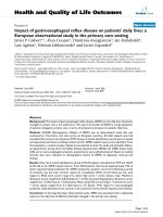
We assume that the resistive force is proportional to the
normal displacement at the bone-implant interface. F
i
, the
magnitude of the resistive force, can be written as (figure
1):
Where E is the Young's modulus of bone, A
i
is the area of
triangle i, ℓ
0i
is the thickness of the supporting
bone when it is undeformed and Δℓ
i
is the change
in thickness of the bone due to displacement of the pros-
thesis. Δℓ
i
can also be written as:
with the displacement of the centre of gravity of tri-
angle i. and should have the same sense, because
otherwise the prosthesis becomes loose in point C
i
.
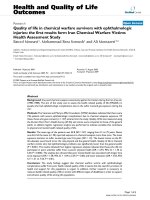
Figure 2a shows a prosthesis with an external load on
the head H. This situation is of course mechanically equiv-
alent to the situation shown in figure 2b, where the
moment in point O is due to the pure force on the
head H of the prosthesis (in other words: can be
F
i
JGJ
FFn
iii
JGJJGJ
=− ⋅ for each triangle i
(1)
F
EA
i
i
ii
=
⎛
⎝
⎜
⎞
⎠
⎟
⋅
A
A
0
Δ
(2)
ΔΔ Δ
ΔΔ
A
JGJJJ JGJJGJJJ JGJ
A
iCii Cii
i
rn rn=⋅ ⋅>
=
when and
when
0
0 rrn
Ci i
JGJJJ JGJ
⋅≤0
(3)
Δr
Ci
JGJJJ
Δr
Ci
JGJJJ
n
i
JGJ
R
JG
M
JGJ
R
JG
M
JGJ
One element of the prosthesis surface supported by boneFigure 1
One element of the prosthesis surface supported by
bone.
Journal of Orthopaedic Surgery and Research 2008, 3:44 />Page 4 of 9
(page number not for citation purposes)
deduced from as: ). We will continue with
the representation in 2b.
The principle of virtual work says that:
With external forces , moments and rotations .
Virtual displacement of C
i
can be written as:
Likewise, the real displacement of C
i
can be written
as:
The prosthesis stem has six degrees of freedom. Thus, (4)
gives rise to six scalar equations, but in this study only the
case of pure axial rotation is illustrated. Axial rotation of
the prosthesis stem corresponds with a virtual displace-
ment:
Using (7) in (5) gives:
And the set of equations (4) leads to only one non-zero
equation:
If we assume that the real displacement of the prosthesis
due to this load is a rotation around the vertical axis Δ
θ
,
we get:
and:
If we define the resistance against axial rotation as the
external moment which is needed to make the prosthesis
rotate over one radian, this is equal to:
Similar expressions can be derived for resistance against
subsidence and resistance against inclination of the pros-
thesis. In this study, only axial rotation is considered
because the largest micromotions occur under torsional
loading of the prosthesis [13,18]. The resistance against
axial rotation is further referred to as antirotation.
An algorithm for reading an STL representation of the
prosthesis stem geometry and calculating the resistance
against rotation and the estimated rotation Δ
θ
under a tor-
sional moment M
z
was implemented in MATLAB (The
Mathworks, Natick, MA, USA). The numerical accuracy of
the MATLAB implementation was verified on a simplified
model of a rectangular beam with a coarse STL mesh.
Finite Element model
For five stem designs, a FE model of the bone-implant
complex was built, that aimed at replicating the simplified
R
JG
MRHO
JGJJGJGJJJ
=×
Rr M F r
OiCi
i
JGJGJJJ JGJJGJJGJJGJJJ
⋅+⋅+ ⋅ =
∑
ddq d
0
(4)
R
JG
M
JGJ
dq
JGJ
d
r
Ci
JGJJJ
dddq ddq
rr OCr r
Ci O i O Ci
JGJJJ J GJJJ J GJJGJJJJ J GJJJ J GJJGJ
=+× =+×
(5)
Δr
Ci
JGJJJ
ΔΔΔ ΔΔrr OCr r
Ci O i O Ci
JGJJJ J GJJJ J GJJ J GJJJJ J GJJJ J GJJ J GJ
=+×=+×
(6)
ddqdq
r
O
JGJJJ J GJ
=
()
=
()
000 00 and
(7)
ddqdq
ry x
Ci Ci Ci
JGJJJ
=− ⋅ ⋅
()
0
(8)
M
EA
i
i
rn yn xn
z Ci i Ci ix Ci iy
i
−⋅⋅
⎛
⎝
⎜
⎞
⎠
⎟
⋅− +
()
⎡
⎣
⎢
⎢
⎤
⎦
⎥
⎥
∑
A
JGJJJ JGJ
0
Δ== 0
(9)
ΔΔΔry x
Ci Ci Ci
JGJJJ
=− ⋅ ⋅
()
0
(10)
Δ
q
=
⋅⋅− +
()
∑
M
z
E
A
i
y
Ci
n
ix
x
Ci
n
iy
i
A
0
2
(11)
E
Aynxn
i Ciix Ciiy
i
A
0
2
⋅⋅−+
()
∑
(12)
Loading on a hip prosthesisFigure 2
Loading on a hip prosthesis. (a) single force on the
head (b) equivalent combination of force and moment
on the stem. If is considered as a vector with three com-
ponents (R
x
, R
y
, R
z
), would cause torque around the
three axes and is represented by double-arrow-headed vec-
tor components (M
x
, M
y
, M
z
). In this study, only M
z
was con-
sidered.
R
JG
R
JG
M
JGJ
R
JG
M
JGJ
Journal of Orthopaedic Surgery and Research 2008, 3:44 />Page 5 of 9
(page number not for citation purposes)
assumptions of the analytical model as good as possible.
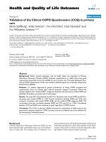
The stems were chosen in such a way that they span a wide
range of antirotation values, based on the analytical
model. STL-files of the stem geometries were provided by
the university hospital orthopaedics department, which
allowed calculation of the resistance against axial rotation
with the proposed analytical model. Export of stem
geometries in STL format was available as a utility within
the system software of the IMP system used in the Leuven
university hospital. The antirotation values for all five
stems are shown in table 1. The names of the stems refer
to their mutual ranking, based on the antirotation values;
the resistance against rotation increases from left
(RotaMIN) to right (RotaMAX) in table 1. The stem
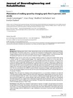
geometries are shown in figure 3.
In order to relate the results from the FE simulations with
the analytical model, the conditions of the analytical
model explained above have to be fulfilled in the FE sim-
ulations as well. By applying a uniform extrusion around
the prosthesis, a bone layer of homogeneous thickness of
10 mm was created. To comply with the condition of
complete contact between bone and prosthesis, the cavity
in the bone was obtained directly from the prosthesis vol-
ume. Frictionless touching contact was defined between
the prosthesis and the bone. Finally, the constraints in the
FE model prohibit all movements of the outer surface of
the bone. Linear tetrahedral 4-node elements (TET4 type)
were used to build the FE models and coincident nodes
were used at the bone-stem interface. The resulting mod-
els had a number of elements ranging from 46000 to
53000. The element size was 3 mm for the outer surface of
the bone mantle, and 2 mm for the prosthesis surface and
the inner bone mantle (i.e. in contact with the stem).
Internal coarsening was used. Mesh refinements were
applied at edges and where stress concentrations were
expected.
Calculations were performed with MARC/Mentat FE soft-
ware (MSC.Software, NL). Bone and prosthesis were
assumed to have a Poisson's ratio of 0.3; the Young's
modulus used for the titanium stems was 114000 MPa;
the bone was assumed to be trabecular bone and was
given a Young's modulus of 233 MPa [29]. The low stiff-
ness of trabecular bone results in larger stem displace-
ments, which improves the relative accuracy of the FE
results.
Both titanium and bone material were assumed isotropic
and linear elastic. For comparison with the analytical
model, all five prostheses were subjected to internal-rota-
tion torsional moments of 4 Nm, 10 Nm and 20 Nm
along the z-axis. The maximum load of 20 Nm corre-
sponds to the highest torsional loads to which a hip pros-
thesis is exposed, i.e. under stair-climbing [18]. The
corresponding rotation angle was obtained for each load
case. Based on the antirotation values of the stems, the
rotation angles predicted by the analytical model could
also be calculated under the same torsional loads. The run
time of an FE analysis ranged from 45 minutes up to 60
minutes. The run times of the MATLAB implementation
of the analytical model were less than 10 seconds.
Results
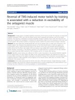
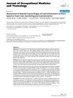
The progress of the stem rotation about the z-axis as a
function of the applied torsional load, obtained from the
FE simulations, is shown in figure 4 for all five prostheses.
The lines connecting the data are merely for visualisation
and have no further meaning.
The stability order of the stems resulting from the FE sim-
ulations is in fairly good accordance with their ranking
based on the antirotation values; RotaMAX exhibits the
smallest rotation angles, RotaHIGH is the second most
stable stem, closely followed by RotaMED. Only Rota-
LOW and RotaMIN have switched places in the stability
ranking obtained with FEM: for RotaMIN, smaller rota-
tion angles are found than for RotaLOW, which is the least
stable stem. The stability ranking of the stems is inde-
pendent of the applied torsional load, except that
RotaMED has a smaller rotation angle at 4 Nm than Rota-
HIGH. An approximately linear progress of the rotation
angle with the applied torsional moment was found for
all five stems over the observed loading interval.
Upper and anteroposterior view of the five stem geometriesFigure 3
Upper and anteroposterior view of the five stem
geometries. From left to right: RotaMIN, RotaLOW,
RotaMED, RotaHIGH and RotaMAX.
Journal of Orthopaedic Surgery and Research 2008, 3:44 />Page 6 of 9
(page number not for citation purposes)
The expected inducible displacements were also calcu-
lated with the analytical model, under the same torsional
loads; the rotation angles could be derived from the anti-
rotation values, assuming a linear relationship between
the applied load and the resulting rotation of the stem.
For ease of comparison, the rotation angles calculated
with the analytical model as well as those obtained from
the FE simulations are shown in table 2. When comparing
the results for both assessment techniques, the rotation
angles predicted by the analytical model turn out to be
two to three orders of magnitude smaller than those
obtained using FEM.
Discussion
In this study, a mathematical formulation is proposed to
numerically predict the potential primary stability of
cementless hip stems. This analytical approach is based
upon the principle of virtual work and a straightforward
mechanical model. The only input needed is an STL-file of
the stem, which can easily be obtained from most CAD-
Table 1: Resistance against axial rotation for the five stem designs, calculated with the analytical model.
RotaMIN RotaLOW RotaMED RotaHIGH RotaMAX
Resistance against axial rotation [Nm/rad] 3.40E+05 4.66E+05 7.81E+05 9.87E+05 1.25E+06
Rotation angle as a function of the applied torsional loadFigure 4
Rotation angle as a function of the applied torsional load. Calculated for the finite element models of the five stem
geometries implanted in a trabecular bone mantle.
Journal of Orthopaedic Surgery and Research 2008, 3:44 />Page 7 of 9
(page number not for citation purposes)
systems. In this way, the model provides a fast and inex-
pensive measure for the expected primary stability.
Such quantification of the primary stability might be use-
ful for several purposes. The range of micromotions meas-
ured under similar loading conditions varied
considerably among different in vitro studies
[12,13,16,17]. Considering this large experimental varia-
bility, several authors have indicated that a theoretical
approach could be useful in determining the potential pri-
mary stability of a certain hip stem. Also in preoperative
planning systems for THRs, quantification of the primary
stability might be an excellent measure for the expected
long-term results. Fast assessment of the primary stability
might be even more beneficial for IMP-systems, like the
one used at our university hospital orthopaedics depart-
ment [28]. In this case, the prosthesis is designed intraop-
eratively, based on the geometry of the reamed cavity. This
necessitates a fast stability quantification of the proposed
stem design, to limit the operation time.
Several other methods have been suggested to quantify
the primary stability of a cementless stem without the
need for measurements [8,9,21]. However, to our knowl-
edge, all the alternatives reported in literature rely on the
use of FEM. The possibilities with FEM are very extensive:
it allows a complete mapping of the interface micromo-
tion [30,31] and the effect of the surrounding bone qual-
ity can be taken into account using a FE model of the
proximal femur [4]. But the use of FEM also has some
important drawbacks: the introduction of FEM in clinical
practice would require high performance computing
hardware to keep the runtimes within acceptable limits. In
combination with the needed specialised software, this
would result in much more expensive THRs. Another
important consideration is that clinical personnel usually
do not have sufficient expertise in computational
mechanics. Therefore, emphasis must be placed upon
developing a computer interface that is easy to use for the
surgeon [10]. The analytical model presented in this study
could be considered as a first attempt to provide a theoret-
ical measure for the primary stability of cementless hip
stems without using FEM. This implies that the proposed
analytical approach does not suffer from the main disad-
vantages of FEM: it provides a fast and inexpensive meas-
ure of the primary stability, and the required human-
computer interaction is very limited. The drawback is that
the stability feedback obtained from the analytical model
is rather limited and not quantitative: critical information
concerning primary stability might be lost due to the
strong simplifications of the model, and this could com-
promise the relevance of the feedback. This latter concern
is addressed in this study: for five stem designs, the resist-
ance against axial rotation was assessed using FEM on the
one hand and the analytical model on the other.
With respect to the FE models, the analytical model pre-
dicts a very stiff stability behaviour: stem rotation was
found to be two to three orders of magnitude smaller for
all loadcases, compared with the FE simulations. The rota-
tion values obtained with the FE models correspond to
displacements that are in the same order of magnitude as
those found in literature [9,12,13,16,17]. For instance,
under a simulated torsional load of 20 Nm, the largest dis-
placements at the stem/femur interface varied between
216
μ
m (for RotaMAX) and 684
μ
m (for RotaLOW) for all
five stems. This means that the stability behaviour pre-
dicted by the analytical model is unrealistically stiff.
Although the FE models used in this study were built
according to the simplified assumptions of the analytical
model, some important differences remain that can
explain a stiffer behaviour of the analytical model; first of
all, shearing deformation of the bone is not considered in
the analytical model: it assumes that the bone surround-
ing the stem will only deform under radial compression,
and that the resulting resistive force is proportional to the
compression of the bone. It is however to be expected that
some shear deformation of the bone will also occur, par-
tially because the inner surface of the bone mantle will
rotate with respect to the outer surface, due to the transfer
of the torsional load. Exclusion of the shearing of the
bone might result in a much stiffer behaviour of the bone-
implant complex.
A second important difference concerns the displacement
of the stem: the analytical model assumes that the stem
Table 2: Rotation angles*, obtained with FEM and with the analytical model.
Moment [Nm] RotaMIN RotaLOW RotaMED RotaHIGH RotaMAX
FEM 4 5,03E-03 5,88E-03 1,71E-03 2,82E-03 1,23E-03
10 1,39E-02 1,77E-02 7,11E-03 6,45E-03 4,47E-03
20 2,93E-02 3,26E-02 1,38E-02 1,20E-02 8,76E-03
Analytical model 4 1,18E-05 8,58E-06 5,12E-06 4,05E-06 3,20E-06
10 2,94E-05 2,15E-05 1,28E-05 1,01E-05 8,00E-06
20 5,88E-05 4,29E-05 2,56E-05 2,03E-05 1,60E-05
*Angles expressed in radians, for all five stems, under torsional loads of 4 Nm, 10 Nm and 20 Nm.
Journal of Orthopaedic Surgery and Research 2008, 3:44 />Page 8 of 9
(page number not for citation purposes)
displacement under torsional load will be a pure rotation
about a vertical axis through the centre of gravity of the
stem. However, the FE simulations have shown that the
stem displacement is more complex: for all cases, the ver-
tical rotation axis is shifted along the mediolateral axis
with respect to the centre of gravity, and in some cases
some tilting of the stem was also found. Preliminary FE
tests have shown that allowing the stem only to rotate
about a vertical axis through the centre of gravity results in
much smaller simulated stem rotations. The effect of both
excluding the shearing deformation of the bone and
restricting the displacement of the stem to a rotation
about the centre of gravity will be addressed in the contin-
uation of the research.
The stability order of the stems was in reasonable agree-
ment for both methods; the analytical model predicts the
same stability ranking as the FE simulations, except that
RotaMIN and RotaLOW switched places. However, the
difference in the antirotation values for both stems is
small. Figure 4 also shows a gap in the results between the
two least stable stems, RotaMIN and RotaLOW, and the
other three stems. This gap is also present in the antirota-
tion values of the stems and in the resulting rotation
angles. Based on these results, the analytical model seems
to be useful as a relative measure for the primary stability
of cementless hip stems. In a recent study by Prendergast
et al., inducible displacements were measured for four
stem designs in in vitro experiments and a stability rank-
ing of the stems was based upon these measurements
[20]. It was found that this stability ranking of the stems
correlated well with their clinical performance. Similarly,
it might be useful to seek a relation between the stability
ranking of stems based on the analytical model and their
clinical performance; this might result in a threshold anti-
rotation value that can be used to distinguish between
stems with sufficient and insufficient primary stability;
new stem designs with an antirotation value lower than
this threshold could then be dismissed without the need
for measurements. However, for the time being, these are
only speculations; in order to validate the analytical
model, more stems need to be included in the study, and
the antirotation values should be compared with in vitro
measurements of the primary stability of implanted
stems.
Indeed, the stability order of the stems might be different
when more realistic models of the bone-implant complex
or truly implanted stems are observed: instead of a perfect
fit-and-fill of the cavity, gaps will occur at the bone-
implant interface; the contact between the prosthesis and
the bone is not frictionless, but frictional forces will con-
siderably contribute to the resistance against axial rotation
[32]; the prosthesis makes contact with cortical as well as
trabecular bone, and the bone mantle does not have a
homogeneous thickness and stiffness; the outer surface of
the bone mantle is not rigidly fixed, it can also deform. All
of these simplified assumptions, which are considered in
this study, might result in an incorrect stability ranking of
the stems. In that case, the analytical model should be
refined, as to eliminate the simplification(s) that cause the
ranking error. In a combined experimental and FE model-
ling study on the rotational stability of cementless THR
stems [33], FE-predicted rotational micromotions were 2–
20 times larger with a friction coefficient f = 0.3 than with
f = 0 and this suggests that consideration of friction
should be a priority when the analytical model is to be
refined.
Conclusion
In conclusion, it was found that the analytical model pre-
dicts an unrealistically stiff stability behaviour. Although
the FE models used in this study aimed at replicating the
simplified assumptions of the analytical model, some
important differences occurred with respect to the stabil-
ity behaviour: stem displacement resulting from a pure
torsional load is not always a pure rotation about a verti-
cal axis, as is assumed by the analytical model. Instead,
the displacement path followed by the stem is imposed by
the shape of the contact surface. Secondly, bone deforma-
tion is modelled as pure radial compression in the analyt-
ical model. This assumption will also significantly reduce
the predicted displacements, since shear deformation of
the bone is excluded. Both of these issues will be
addressed in the continuation of the research.
Nevertheless, the analytical model seems to be useful as a
comparative tool for the primary stability of cementless
hip stems. The stability ranking obtained for real
implanted stems might differ from the ranking obtained
with the analytical model, due to the strong simplifica-
tions on which the model is based. Future research should
therefore consider more realistic models of the bone-
implant complex or in vitro measurements of the primary
stability. If necessary, further refinements should be made
to the model to eliminate the simplifications that cause
errors in the stability ranking.
Competing interests
The authors declare that they have no competing interests.
Authors' contributions
MEZ designed and analyzed the first versions of the finite
element models and drafted the initial manuscript. LL
developed the analytical model for hip stem stability, with
input from GVDP and SVNJ. NS refined and re-analyzed
the finite element models and extended the manuscript
accordingly. MM provided clinical background and con-
tributed to the interpretation from a practitioner's view.
GVDP and SVNJ conceived and coordinated the study as a
Publish with BioMed Central and every
scientist can read your work free of charge
"BioMed Central will be the most significant development for
disseminating the results of biomedical research in our lifetime."
Sir Paul Nurse, Cancer Research UK
Your research papers will be:
available free of charge to the entire biomedical community
peer reviewed and published immediately upon acceptance
cited in PubMed and archived on PubMed Central
yours — you keep the copyright
Submit your manuscript here:
/>BioMedcentral
Journal of Orthopaedic Surgery and Research 2008, 3:44 />Page 9 of 9
(page number not for citation purposes)
comparison of analytical and finite element modeling to
predict stem stability. Interpretation of the comparison
between analytical and FE model results was a joint effort
by MEZ, NS, LL, GVDP and SVNJ. All authors read and
approved the final manuscript.
Acknowledgements
This research was funded by a grant from the K.U.Leuven Research council,
project OT/03/31 on "The role of biomechanical parameters in the success
or failure of cementless orthopaedic implants" (MEZ, NS). Contributions
were made as part of regular academic research effort by K.U.Leuven per-
sonnel (LL, SVNJ, GVDP) and UZ Leuven personnel (MM).
References
1. Pilliar RM, Lee JM, Maniatopoulos C: Observations on the effect
of movement on bone ingrowth into porous-surfaced
implants. Clin Orthop Relat Res 1986:108-113.
2. Søballe K, Hansen ES, Rasmussen H, Jorgensen PH, Bunger C: Tissue
ingrowth into titanium and hydroxyapatite-coated implants
during stable and unstable mechanical conditions. J Orthop Res
1992, 10:285-299.
3. Diels J, in cooperation with Mertens R, Boly J, de Bethune X, Hutse-
baut L, Oever R Van Den: CM Themadossier "Totale Heupprothese",
Variatie in medische praktijk en lange termijn-resultaten. Brussels 2000.
4. Wong AS, New AMR, Isaacs G, Taylor M: Effect of bone material
properties on the initial stability of a cementless hip stem: a
finite element study. Proc Inst Mech Eng [H] 2005, 219:265-275.
5. Pancanti A, Bernakiewicz M, Viceconti M: The primary stability of
a cementless stem varies between subjects as much as
between activities. J Biomech 2003, 36:777-785.
6. Ramamurti BS, Orr TE, Bragdon CR, Lowenstein JD, Jasty M: Factors
influencing stability at the interface between a porous sur-
face and cancellous bone: A finite element analysis of a
canine in vivo micromotion experiment. J Biomed Mater Res
1997, 36:274-280.
7. Viceconti M, Pancanti A, Varini E, Traina F, Cristofolini L: On the
biomechanical stability of cementless straight conical hip
stems. Proc Inst Mech Eng [H] 2006, 220:473-480.
8. Ando M, Imura S, Omori H, Okomura Y, Bo A, Baba H: Nonlinear
three-dimensional finite element analysis of newly designed
cementless total hip stems. Artificial organs 1999, 23:339-346.
9. Viceconti M, Brusi G, Pancanti A, Cristofolini L: Primary stability
of an anatomical cementless hip stem: A statistical analysis.
J Biomech 2006, 39:1169-1179.
10. O'Toole RV, Jaramaz B, DiGioia AM, Visnic CD, Reid RH: Biome-
chanics for preoperative planning and surgical simulations in
orthopaedics. Comput Biol Med 1995, 25:183-191.
11. Viceconti M, Davinelli M, Taddei F, Cappello A: Automatic gener-
ation of accurate subject-specific bone finite element models
to be used in clinical studies. J Biomech 2004, 37:1597-1605.
12. Burke D, O'Connor D, Zalenski E, Jasty M, Harris W: Micromotion
of cemented and uncemented femoral components. J Bone
Joint Surg Br 1991, 73:33-37.
13. Callaghan JJ, Fulghum ChrS, Glisson RR, Stranne SK: The effect of
femoral stem geometry on interface motion in uncemented
porous-coated total hip prostheses. J Bone Joint Surg Am 1992,
74(6):839-846.
14. Phillips TW, Nguyen LT, Munro SD: Loosening of cementless
femoral stems: A biomechanical analysis of immediate fixa-
tion with loading vertical, femur horizontal. J Biomech 1991,
24:37-48.
15. McKellop H, Ebramzadeh E, Niederer PG, Sarmiento A: Compari-
son of the stability of press-fit hip prosthesis femoral stems
using a synthetic model femur. J Orthop Res 1991, 9:297-305.
16. Nunn D, Freeman MAR, Tanner KE, Bonfield W: Torsional stability
of the femoral component of hip arthroplasty: Response to
anteriorly applied load. J Bone Joint Surg Br 1989, 71(3):452-455.
17. Walker PS, Schneeweis D, Murphy S, Nelson P: Strains and micro-
motions of press-fit femoral stem prostheses. J Biomech 1987,
20:693-702.
18. Bergmann G, Deuretzbacher G, Heller M, Graichen F, Rohlmann A,
Strauss J, Duda GN: Hip contact forces and gait patterns from
routine activities. J Biomech 2001, 34:859-871.
19. Harman MK, Toni A, Cristofolini L, Viceconti M: Initial stability of
uncemented hip stems: an in-vitro protocol to measure tor-
sional interface motion. Med Eng Phys 1995, 17:163-171.
20. Britton JR, Prendergast PJ: Preclinical testing of femoral hip
components: an experimental investigation with four pros-
theses. J Biomech Eng 2005, 127:872-880.
21. Ruben RB, Folgado J, Fernandes PR: Three-dimensional shape
optimization of hip prostheses using a multicriteria formula-
tion. Struct Multidisc Optim 2007, 34:261-275.
22. Capello WN: Preoperative planning of total hip arthroplasty.
Instructional Course Lectures 1986, 35:249-257.
23. Viceconti M, Chiarini A, Testi D, Taddei F, Bordini B, Traina F, Toni
A: New aspects and approaches in pre-operative planning of
hip reconstruction: a computer simulation. Langenbecks Arch
Surg 2004, 389:400-404.
24. Lattanzi R, Viceconti M, Zannoni C, Quadrani P, Toni A: Hip-Op: an
innovative software to plan total hip replacement surgery.
Med Inform Internet Med 2002, 27(2):71-83.
25. Heller MO, Schröder J, Matziolis G, Sharenkov A, Taylor WR, Perka
C, Duda GN: Musculoskeletal load analysis. A biomechanical
explanation for clinical results – and more? Orthopäde 2007,
36:188-194.
26. Benedetti MG, Montanari E, Catani F, Leardini A: Pre-operative
planning and gait analysis of total hip replacement following
hip fusion. Comp Meth Prog Biomed 2003, 70:215-221.
27. Mjöberg B: The theory of early loosening of hip prostheses.
Orthopedics 1997, 20(12):1169-1175.
28. Mulier JC, Mulier M, Brady LP, Steenhoudt H, Cauwe Y, Goossens M,
Elloy M: Intraoperative production of femoral prostheses. In
Joint replacement – State of the Art Edited by: Coombs R, Gristina A,
Hungerford D. Surrey, England: Orthotext; 1990:163-169.
29. Van Rietbergen B, Weinans H, Huiskes R, Odgaard A: A new
method to determine trabecular bone elastic properties and
loading using micromechanical finite-element models. J Bio-
mech 1995, 28:69-81.
30. Tissakht M, Eskandari H, Ahmed AM: Micromotion analysis of the
fixation of total knee tibial component. Comp & Struct 1995,
56:365-375.
31. Dammak M, Shirazi-Adl A, Zukor DJ: Analysis of cementless
implants using interface nonlinear friction – experimental
and finite element studies. J Biomech 1997, 30:121-129.
32. Dammak M, Shirazi-Adl A, Schwartz M, Gustavson L: Friction prop-
erties at the bone-metal interface: Comparison of four dif-
ferent porous-metal surfaces. J Biomed Mat Res 1997,
35:329-336.
33. Sauwen N: Voorspelling van implantaatfixatie op basis van
pre-operatieve CT-beelden [Prediction of implant fixation
based on pre-operative CT images]. In MSc Eng Thesis 06EB01
K.U.Leuven, Mechanical Engineering Department; 2006.