From Turbine to Wind Farms Technical Requirements and Spin-Off Products Part 3 potx
Bạn đang xem bản rút gọn của tài liệu. Xem và tải ngay bản đầy đủ của tài liệu tại đây (1.11 MB, 15 trang )
Wind Farms and Grid Codes
19
• Portugal – REN: Portaria n.º 596/2010 de 30 de Julho
• Canada – AESO: “Wind Power Facility - Technical Requirements”, Revision 0, November,
15 2004.
• Australia – AEMC: “National Electricity Rules (NER)”, Version 39, 16 September 2010
• Ireland – EIRGRID: “WFPS1- Controllable Wind Farm Power Station Grid Code Provisions”,
EirGrid Grid Code, Version 3.4, October 16
th
2009.
Fault ride through requirements are described by a voltage vs. time characteristic, denoting
the minimum required immunity of the wind power station. The fault ride through
requirements also include fast active and reactive power restoration to the prefault values,
after the system voltage returns to normal operation levels. Some codes impose increased
reactive power generation by the wind turbines during the disturbance, in order to provide
voltage support, a requirement that resembles the behaviour of conventional synchronous
generators in over-excited operation.
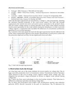
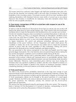
Fig. 1 presents in the same graph the fault ride through requirements from the different Grid
Codes. These requirements depend on the specific characteristics of each power system and
the protection employed and they deviate significantly from each other.
Fig. 1. Fault ride through requirements.
3. Wind turbine fault-ride through
As it has been said, one of the main problems for power quality are voltage dips. Due to
high renewable penetration level in transmission system, Transmission System Operators
(TSO) demand to this sort of energy source support voltage under voltage sags. This
obligation has provoked a huge investment in devices to support wind systems during
voltage dips.
Fig. 2 shows the three main technologies in the wind turbine industry. Their behaviour is
different in continuous operation and during voltage dips.
Fig. 2a shows the fixed-speed wind turbine with asynchronous squirrel cage induction
generator (SCIG) directly connected to the grid via transformer. Fig. 2b represents the
From Turbine to Wind Farms - Technical Requirements and Spin-Off Products
20
limited variable speed wind turbine with a wound rotor induction generator and partial
scale frequency converter on the rotor circuit known as doubly fed induction generator
(DFIG). Fig. 2c shows the full variable speed wind turbine, with the generator connected to
the grid through a full-scale frequency converter.
Fig. 2. Wind turbine technologies.
DFIG stator is connected directly to the network but its rotor is connected to the network by
means of a power converter which performs the active and reactive power control. A
voltage dip will cause large currents in the rotor of the DFIG to which the power electronic
converter is connected, and a high rotor voltage will be needed to control the rotor current.
When this required voltage exceeds the maximum voltage of the converter, it is not possible
any longer to control the current desired (Morren, de Haan, 2007). This implies that large
current can flow, which can destroy the converter.
In order to avoid breakdown of the converter switches, new DFIG wind turbines are
provided with a system called crowbar connected to the rotor circuit. When the rotor
currents become too high, the converter is disconnected and the high currents do not flow
through the converter but rather into the crowbar resistances. The generator then operates
as an induction machine with a high rotor resistance. When the dip lasts longer than a few
hundreds of milliseconds (T
max_crowbar
), the wind turbine can even support the grid during the
dip (Morren, de Haan, 2007; López et al, 2009).
The full converted wind turbine is connected to the network through a converter; and
therefore the converter controls the wind turbine during de dip in order to fulfill the Grid
Code Requirements.
SCIG are used as fixed speed wind generator due to its superior characteristics such as
brushless and rugged construction, low cost, maintenance free, and operational simplicity.
However it requires large reactive power to recover the airgap flux when a short circuit
occurs in the power system, unless otherwise the induction generator becomes unstable due
GB
GB
a)
b)
c)
GB
Wind Farms and Grid Codes
21
to the large difference between electromagnetic and mechanical torques, and then it requires
to be disconnected from the power system (Muyeen et al, 2009; Muyeen & Takahashi, 2010).
Next section describes different solutions to support the transient behaviour of SCIG and
old DFIG wind turbines that do not fulfill fault ride through requirements.
3.1 Fault ride through solutions
Nowadays, the rapid development of power electronics has made that the old devices for
controlling voltage based on capacitors and reactors have been replaced by Flexible AC
Transmission Systems (FACTS).
New wind turbines have integrated different systems to withstand voltage dips; however
the old wind turbines have to install different FACTS to overcome dips. The main solutions
are installed either in each turbine or in the point of common coupling.
The FACTS used in wind systems can be divided into three categories depending on their
connection (Amaris, 2007; Hingorain, 1999):
• Series device, for example the Dynamic Voltage Restorer (DVR)
• Shunt device, such as Static Voltage Compensator (SVC) and Static Compensator
(STATCOM).
• Series-shunt device. They are a combination of a series and a parallel FACTS. In wind
system Unified Power-Quality Conditioner (UPQC) are used.
Next, these systems are explained.
3.1.1 Static Voltage Compensator (SVC)
Static Voltage Compensator is a shunt-connected var generator o absorber whose output is
adjusted to exchange capacitive or inductive current. Fig. 3 shows the connection of SVC. It
is usually connected between the utility and the generator. SVC can provide reactive power,
from 0 to 1 p.u. depending on voltage (Fig. 3). These devices use electronic switches as
thyristor, which can open or close in few milliseconds.
SVC is considered by some as a lower
cost alternative to STATCOM, although this may not be the case if the comparison is made
based on the required performance and not just in the MVA size, because for the same
contingency and the same system, the required SVC ratings is generally larger than required
STATCOM (Hingorain, 1999, Molinas et al, 2008).
0
0.2
0.4
0.6
0.8
1
1.2
-1.5 -1 -0.5 0 0.5 1 1.5
Current (p.u.)
Voltage (p.u.)
Fig. 3. Different topologies of SVC and V-I characteristic.
3.1.2 Static Synchronous Compensator (STATCOM)
Static Synchronous Compensator is a voltage source converter which can inject or absorb
reactive current in an AC system, modifying the power flow. STATCOM can provide
From Turbine to Wind Farms - Technical Requirements and Spin-Off Products
22
reactive power independently of the voltage, as shown the voltage-current characteristic in
Fig. 4. It comprises a converter, connected in parallel between utility and the generator, and
a DC current stage as it is shown in Fig. 4.
STATCOM is the evolution of SVC, but STATCOM have continuous control and can
compensate both power factor and voltage simultaneously. Other advantage of STATCOM
is its dynamic capacity getting small response times.
0
0.2
0.4
0.6
0.8
1
1.2
-1.5 -1 -0.5 0 0.5 1 1.5
Current (p.u.)
Voltage (p.u.)
Fig. 4. Scheme of the connection of the STATCOM and V-I characteristic.
3.1.3 Dynamic Voltage Restorer (DVR)
Dynamic Voltage Restorer is a series compensator, which works inserting a voltage of
magnitude and frequency necessary. Fig. 5 shows the scheme of this FACTS.
DVR consists of a medium voltage switchgear, a coupling transformer, filters, rectifier,
inverter, and energy source (e.g. storage capacitor bank) and control and protection system.
DVR can inject or absorb real and reactive power independently by an external storage
system without reactors and capacitors (Wizmar & Mohd, 2006).
If the storage system is a capacitor bank, during normal operation it will be charging, and
when a swell or voltage sag is detected this capacitor will discharge to maintain load voltage
supply injecting or absorbing reactive power.
Fig. 5. Scheme of Dynamic Voltage Restorer.
3.1.4 Unified Power Quality Conditioner (UPQC)
Unified Power Quality Conditioner is a combination of a series and a shunt FACTS. Its
target is to improve power quality compensating voltage flicker, unbalance, negative-
sequence current and harmonics. Fig. 6 shows the scheme of connection of UPQC.
UPQC (Khadkikar et al, 2004) comprises two voltage source inverters connected back to
back and sharing a dc link. The shunt inverter helps in compensating load harmonic current
DC
Stage
Wind Farms and Grid Codes
23
and maintains dc voltage at constant level. The second inverter is connected in series by
using a series transformer and helps in maintaining the load voltage sinusoidal and
compensate voltage dips and swells.
Control system of UPQC is formed by the positive sequence detector, the series inverter
control and the shunt inverter control.
Fig. 6. Scheme of Unified Power-Quality Conditioner.
4. Fault ride through certification procedure for power generating units
Once the requirements for wind power system have been established, another important
point is how wind turbine manufacturers and wind park operators can prove the fulfilment
of Grid Codes. The Spanish Wind Energy Association (AEE) has developed the document
“Procedure for Verification Validation and Certification of the Requirements of the OP 12.3
on the Response of Wind Farms in the Event of Voltage Dips” (PVVC), and the German
Fördergesellschaft Windenergie und andere Erneuerbare Energien (FGW) the document
“Technical Guidelines for Power Generating Units. Part 8. Certification of the electrical
characteristics of power generating units and systems in the medium, high- and highest-
voltage grids“ that describes the procedures to certify wind power installations according
their corresponding Grid Codes.
This section describes the steps to fulfil certificate wind systems by these two procedures.
4.1 PVVC procedure
The PVVC define two possible processes to verify the conformity with the response
requirements established in OP 12.3:
• The General Verification Process
• The Particular Verification Process
The General Verification Process consists of verifying that the wind farm does not
disconnect and that the requirements stated on the OP 12.3 are met by means of:
• Wind turbine and/or FACTS test
• Wind turbine and/or FACTS validation
• Wind farm simulation
Then three processes must be followed to verify an installation by the General Verification
Process and three reports are needed. Next figures show a scheme of these three processes
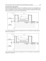
and the three reports obtained. Fig. 7 shows the scheme of the field test process, Fig. 8 the
model validation process and Fig. 9 the verification process.
From Turbine to Wind Farms - Technical Requirements and Spin-Off Products
24
Fig. 7. Field test process.
Fig. 8. Validation process.
Fig. 9. Verification process.
The particular verification process obtains the direct wind farm verification by testing the
dynamic elements of the wind farm. In this case, only the process shown in Fig. 7 must be
performed. Model validation and wind farm simulation are not needed. In this case, the
conditions of the field test will be harder than those of the general verification process.
The particular verification process is faster and cheaper than the general verification
process. Therefore, wind turbine manufacturer and wind farm operators would prefer this
process if the wind turbine or the system wind turbine + FACTS can be tested and can ride
through the voltage dip test defined in the Particular Verification Process. General
Verification Process is necessary in those wind farms whose wind turbines can not ride
through the voltage dip defined in the particular process and a compensating system is
installed on the wind farm substation to fulfil the OP 12.3 requirements.
Wind Farms and Grid Codes
25
4.2 FGW-TG8 procedure
The FGW-TG8 defines two processes depending on the date of commission of the
installation that is going to be certificate. If the installation has been commissioned after
01.01.2009 must follow the process for “new generating units”. If the installation has been
commissioned after 31.12.2001 and before 01.01.2009 the certification must follow the
process for “old systems”.
To certify “new generating units” the applicant must provide:
• Verification of type testing according to FGW-TG3 (FGW, 2009).
• A comprehensive computer based model of the power generating unit, which may be
encapsulated as a black box model. This model needs to be suitable to represent the
measuring situation of the type tests in accordance with FGW-TG3 (FGW, 2009).
• An open, where necessary simplified, model of the power generating unit. This open
model must allow the certifier to follow the logical links between control loops in the
relevant system controls. The degree of detail of the open model must be clarified in
advance between the certification authority and the manufacturer. In some cases it may
be sufficient to present block diagrams. It is necessary to comprehensively describe fault
detection for verification of performance in a fault situation.
To certify “old systems” the applicant must provide Verification of type testing according to
FGW-TG3. Furthermore the document must contain the specification of the original power
generating unit and the specifications on the refitted power generating unit. Model
validation does not form part of this procedure.
Fig. 10. Process of new unit certification.
From Turbine to Wind Farms - Technical Requirements and Spin-Off Products
26
Fig. 11. Process of old unit certification.
5. Voltage dip test
In order to test the behaviour of the turbine when a voltage dip occurs and the compliance
with Grid Codes, a device able to generate voltage dips is required. This device must create
a voltage variation according to the regulations of the different countries in order to check
that the tested wind turbine fulfils the established requirements, such as voltage ride-
through, short circuit contribution and power factor.
5.1 Voltage dip generator
Voltage dip generators are based on the use of two impedances, as it is shown in Fig. 12
(Niiranen, 2005, 2006; Gamesa eólica, 2006; Gamesa innovation and technology, 2006). The
parallel impedance enables the generation of the fault while the series impedance
immunizes the grid from the dip and the test can be performed without affecting other
systems connected to it.
Fig. 12. Dip generator scheme and its position with respect to the windmill and the wind farm.
5.1.1 20 kV 5 MW Voltage dip generator
This section describes the design of a 20 kV, 5 MW voltage dip generator. It is installed in a
trailer, so it is able to move to the wind turbine location (García-Gracia et al, 2009).
Wind Farms and Grid Codes
27
Fig. 14 shows a scheme of this voltage dip generator. It is based on an inductive divider
comprised of a series and a parallel branch, and its main components are a three-phase
series impedance (4) at the system input, a parallel tap transformer (7) and a three-phase
impedance (11) grounded through a control switch in the secondary of the transformer. This
impedance allows the adjustment of the dip depth to the desired value, along with the
regulation of the transformer, because the impedance (11) connected to winding 2 is referred
to winding 1 by multiplying by the square of the turns ratio. Switches (5) and (9) make
possible the generation of a 100% depth voltage dip.
Fig. 13. Picture of the 5 MW test system.
Fig. 14. Scheme of the voltage dip generator.
5.2 Voltage dip test procedure
The system described includes some other control elements in order to perform the voltage
dip generation, which takes place as follows.
Having the by-pass switch (3) on allows the direct connection between the utility and the
generating system (i.e. wind system), eliminating the effect of the insertion of the voltage
dip generator.
Wind
turbine
MV
Network
(2)
(3)
(4) (1)
(6) (5)
(7)
(8)
(11)
(9) (10) (12)
From Turbine to Wind Farms - Technical Requirements and Spin-Off Products
28
Once this switch is open, the generator is connected to the grid through the series
inductances (4), and the switch (6) connecting the parallel branch can be closed, in order to
connect the primary of the transformer (7), which at this point is in no-load operation.
Next, the dip generation switch (8) is closed, connecting the secondary of the transformer to
the impedances (11) or to the short circuit (9) to achieve a deeper voltage dip. Timing the
operation of these switches, the desired dip duration is set. As mentioned before, a 100%
voltage dip can be achieved closing switches (5) and (9) after switch (3) has been open.
The impedance banks (11) have single-phase switches (10) to have the possibility of
performing single-phase, two-phase and three-phase tests.
5.2.1 Wind turbine test according to the Spanish PVVC
The Spanish PVVC distinguish between two different type tests:
• Test for validating the simulation model (General Verification Process)
• Test for direct observance of the OP 12.3 (Particular Verification Process)
For both cases, the wind turbine should be tested for the following operation points:
Registered Active Power Power Factor
Partial load 10% - 30% Prated 0.9 inductive – 0.95 capacitive
Full load > 80% Prated 0.9 inductive – 0.95 capacitive
Table 1. Operation points prior to test.
The depth of the voltage dip must be independent of the wind turbine tested. Therefore, a
no- load test must be performed before the connection of the wind turbine. Thus the series
inductances (4), the transformer taps (7) and the impedances (11) are adjusted with the
switch (2) open.
Table 2 shows the residual voltage, the duration of the voltage dips, and the allowed
tolerances of the tests for direct observance of the OP 12.3 (Particular Verification Process).
Dip
Residual
dip voltage
(Ures)
Voltage
tolerance
(Utol)
Dip
duration
(ms)
Time
tolerance
(Ttol) (ms)
Three phase ≤(20%+Utol) + 3% ≥ (500-Ttol) 50
Isolated two phase ≤(60%+Utol) + 10% ≥ (500-Ttol) 50
Table 2. Voltage dip properties in the no-load test for the Particular Verification Process.
If the objective of the test is the validation of simulation models (General Verification
Process), the minimum voltage registered during the no load test of the faulted phases must
be less than 90%.
Before the wind turbine test, it must be checked that the short circuit power in the test point
is greater than 5 times the generator rated power. This condition is fulfilled by adjusting (4).
Once the voltage dip generator has been adjusted; the test can be performed by closing the
switch (2) of the Fig. 14. The four test categories shown in Table 3 must be carried out.
Therefore, the power generated by the wind turbine must be measured before the voltage
dip, to check the operating point. As the operating point depends on the wind speed, it is
possible that the generated power does not match with one of the operating points shown in
Table 1. In this case, the laboratory has to wait for the needed weather conditions to perform
the test of each operating condition.
Wind Farms and Grid Codes
29
Category Operating point Dip type
1 Partial load Three phase
2 Full load Three phase
3 Partial load Isolated two phase
4 Full load Isolated two phase
Table 3. Test categories.
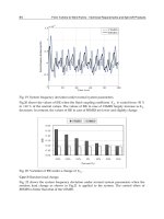
Fig. 15 and Fig. 16 show the measured voltages during a three-phase and a two-phase
voltage dip respectively.
Fig. 15. Three-phase voltage dip: Depth 100%; Duration 510 ms.
Fig. 16. Two-phase voltage dip: Depth 50%; Duration 150 ms.
To guarantee the continuity of supply, the wind turbine will be undergone to three
consecutive tests. If the wind turbine disconnects during this test sequence, four consecutive
tests will be performed. If in this new sequence, the wind turbine disconnects, the test will
be considered invalid.
To verify wind systems by applying the Particular Verification Process, the power and
energy registered must fulfill the requirements shown in Table 4 and Table 5.
Three phase faults OP 12.3 requirements
ZONE A
Net consumption Q < 15% Pn (20 ms) -0.15 p.u.
ZONE B
Net consumption P < 10% Pn (20 ms) -0.1 p.u.
Net consumption Q < 5% Pn (20 ms) -0.05 p.u.
Average I
r
/I
tot
0.9 p.u.
Extended ZONE C
Net consumption I
r
< 1.5 I
n
(20 ms) -1.5 p.u.
Table 4. Power and energy requirements for three phase voltage dips in the Particular
Verification Process.
From Turbine to Wind Farms - Technical Requirements and Spin-Off Products
30
Two phase faults OP 12.3 requirements
ZONE B
Net consumption E
r
< 40% Pn * 100 ms
-40 ms
.
p.u.
Net consumption Q < 40% Pn (20 ms) -0.4 p.u.
Net consumption E
a
< 45% Pn * 100 ms
-45
.
ms p.u.
Net consumption P < 30% Pn (20 ms) -0.3 p.u.
Table 5. Power and energy requirements for isolated two phase voltage dips in the
Particular Verification Process.
Where the zones A, B and C are defined in Fig. 17.
Fig. 17. Classification of the voltage dip in the field test.
5.2.2 Wind turbine test according to the German FGW-TG3
The on-site test should serve the following objectives:
• Validation of the system
• Test the control system and the auxiliary units
For both cases, the wind turbine should be tested for the following operation points:
Registered Active Power
Partial load 10% - 30% Prated
Full load > 90% Prated
Table 6. Operation points prior to test.
In this case, the voltage dip generator must have an X/R ratio of at least 3, and the
symmetrical fault level on the transformer’s high voltage side must be at least 3·Prated.
Dip treshold
Wind Farms and Grid Codes
31
The voltage dip generator must be configured in no-load test to obtain the three phase and
two phase voltage dips with the different depths shown in Table 7 for directly synchronous
generators and Table 8 for the other types, as in the procedure for test according to the
Spanish PVVC. Therefore, in the system shown in the Fig. 14, the series inductances (4), the
transformer taps (7) and the impedances (11) adjusted with the switch (2) open.
Test
number
Ratio of fault voltage
to initial voltage (U/U0)
Fault duration
(ms)
1 0.05 150
2 0.20-0.25 150
3 0.45-0.55 150
4 0.70-0.80 700
Table 7. Voltage drop test for directly coupled synchronous generators.
Test
number
Ratio of fault voltage
to initial voltage (U/U0)
Fault duration
(ms)
1 0.05 150
2 0.20-0.25 550
3 0.45-0.55 950
4 0.70-0.80 1400
Table 8. Voltage drop test for all the other types of generators.
For three phase voltage dips in accordance with test 3 and 4, minimum proportionality
constant (K-factor) is two. This factor is defined in (SDLWindV, 2009) by:
ΔΔ
=⋅
Br
NN
IU
K
IU
(1)
Where
I
B
is the reactive current,
Δ
B
I is the reactive current deviation and
Δ
r
U is the relevant
voltage deviation and is calculated as:
Δ
=Δ +
rt
UUU (2)
Where ΔU is the voltage deviation and
t
U
the dead band, that must be kept at a constant
maximum of 10%
U
N
during each test.
6. Model validation
The Spanish PVVC and the German FGW-TG4 (FGW, 2009) give the procedures to validate
wind turbine systems by comparing the results obtained by simulation and that obtained
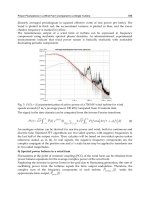
from on-site test. PVVC and FGW-TG4 gives the maximum deviation and the specific time
intervals for the comparison of the results. The Spanish PVVC establishes a time window of
1 s with 100 ms before the voltage dip, and the German FGW-TG4, 500 ms before the voltage
dip and 2 s after the voltage recovery. Fig. 18 shows the different time windows established
in each document. It is important to point out that the time window from the PVVC is fixed
and does not depend on the voltage dip duration whereas the FGW-TG4 depends on it.
From Turbine to Wind Farms - Technical Requirements and Spin-Off Products
32
0.0
0.2
0.4
0.6
0.8
1.0
1.2
0.0 0.5 1.0 1.5 2.0 2.5 3.0 3.5 4.0 4.5
Time (s)
u (p.u.)
Fig. 18. Time window established in the German FGW-TG4 and the Spanish PVVC.
Respect the maximum deviation, in the Spanish PVVC it is constant and equal to 10% in the
time frame, and the German FGW-TG4 establishes these values:
Deviation
F1
Deviation F2
Deviation
F3
Total Deviation
FG
Active Power ΔP/Pn,
Reactive Power ΔQ/Pn
0.07 0.20 0.10 0.15
Reactive current ΔIb/Ir 0.10 0.20 0.15 0.15
Table 9. Maximum deviation in different stages of voltage dip.
Where F1 is the deviation of the mean of steady state areas, F2 the deviation of the mean of
transient areas, F3 the highest deviation in steady state areas and FG the mean of weighted
deviations for P, Q and Ib.
Next the validation process followed for a wind turbine generator from in-field testing
results according to the Spanish PVVC.
6.1 Voltage dip generator model
In PVVC the system shown in Fig. 19 is proposed. In this system, the voltage measured in
the field test is introduced in the simulation and reproduced by a voltage source. Thus, the
wind turbine model is subjected to the same voltage than the wind turbine during the field
test and only the active and reactive power must be compared to validate the model.
Fig. 19. Voltage dip generator representation in validation simulation.
U
dip
I
WTG
G
FGW TG4
time window
PVVC time
window
Wind Farms and Grid Codes
33
6.2 Methodology for calculating power
The PVVC explains the following method to calculating power from the test and simulation
results.
Using the N samples of the instantaneous values of phase voltage (u(n)) and the phase
current (i(n)) the fundamental harmonic can be obtained using the following expressions:
()
1
2
1
0
2
N
n
j
N
n
Uune
N
π
−
⎛⎞
−
⎜⎟
⎝⎠
=
=⋅ ⋅
∑
(5)
()
1
2
1
0
2
N
n
j
N
n
Iine
N
π
−
⎛⎞
−
⎜⎟
⎝⎠
=
=⋅ ⋅
∑
(6)
To calculate the active and reactive power, only the positive sequence component of the
voltage and current are used:
22
33
11 1
1
3
jj
AB C
UUUeUe
ππ
+−
+
⎛⎞
=+⋅+⋅
⎜⎟
⎝⎠
(7)
22
33
11 1
1
3
jj
AB C
IIIeIe
ππ
+−
+
⎛⎞
=+⋅+⋅
⎜⎟
⎝⎠
(8)
The three-phase active and reactive power expressions are obtained from the positive
sequence component of the voltage and current as:
(
)
3cosPUI
ϕ
++
=⋅ ⋅ ⋅
(9)
(
)
3Q U I sen
ϕ
++
=⋅ ⋅ ⋅
(10)
6.3 Model validation
This section describes the model validation process followed for the developed model. Only
the three-phase voltage dip for the full load category is shown, the process for the rest of the
categories would be the same.
The next figure shows the voltage evolution during the field test and the simulation in phase
A. In the simulation, the voltage is introduced by means of a voltage source that reproduces
the voltage during the field test. Therefore, there are no significant differences between test
and simulation. Voltage in phase B and C are similar to voltage in phase A. In the figure, the
blue line represents the voltage obtained during the field test; the red line has been obtained
by simulation and the green line the maximum deviation considered in the Spanish PVVC
(10%).
Table 10 shows that the model is validated in this category (full load, three phase voltage
dip) because the number of the samples with error less than the maximum allowable error
for the active and the reactive power are greater than 85%. Fig. 21 shows the comparison of
the active power results and Fig. 22 the comparison of the reactive power results. In both
figures, the blue line represents the results obtained during the field test; the red line has
been obtained by simulation and the green line the maximum deviation considered (10%).