From Turbine to Wind Farms Technical Requirements and Spin-Off Products Part 6 docx
Bạn đang xem bản rút gọn của tài liệu. Xem và tải ngay bản đầy đủ của tài liệu tại đây (854.72 KB, 15 trang )
4
Frequency Control of Isolated Power
System with Wind Farm by Using
Flywheel Energy Storage System
Rion Takahashi
Kitami Institute of Technology
Japan
1. Introduction
For the recent expansion of renewable energy applications, wind energy generation is
receiving much interest all over the world. Many large wind farms have been installed so far
and recently huge offshore wind farms have also been installed. However, the frequency
variation of power system due to wind generator output fluctuations is a serious problem. If
installations of wind farms continue to increase, frequency control of power system by the
main sources, that is, hydraulic and thermal power stations, will be difficult in the near
future, especially in an isolated power system like a small island which has weak capability
of power regulation. In such a case, the installation may be restricted even though it is a
small wind farm. Though there is such a difficulty, an introduction of the wind energy
utilization is much effective in an isolated power system, because main power plant in a
small island is mostly a diesel engine driven generating plant and it has no good effect on
the environment. Hence, some strategies are necessary to improve the stability of wind farm
output. According to such situations, an application of battery system for the output power
smoothing has been investigated so far, and some experimental studies using practical
facilities are being performed. The battery system is suitable for power compensation with
relatively long period like load leveling. However, since rapid response is necessary to
compensate power variations in an isolated power system, the battery system may not be
appropriate because charging or discharging speed of the battery is not so fast due to its
chemical process. Moreover, the same capacity of electronic power converter as that of the
battery power rating is required. In addition life time of battery is, in general, not so long
and thus frequent replacement of battery cell will be needed. These characteristics cause cost
increase. On the other hand, the application of Flywheel Energy Storage System (called
'FESS' hereinafter) for power compensation is very effective. This system has characteristics
of large energy storage capacity, long life, and rapid response of power control. It has a
heavy weight rotating mass connected to an adjustable speed generator. This chapter adopts
an adjustable speed generator with secondary AC excitation as a driving machine of rotating
mass, because this type of generator has already been put into practice in pumped storage
hydro power plants in Japan [1]. There are also some practical applications of FESS to
improve power system stability [2]. The adjustable speed generators with secondary AC
excitation can control not only active power output but also reactive power output rapidly
From Turbine to Wind Farms - Technical Requirements and Spin-Off Products
66
and independently. Thus smoothing of both output power and grid voltage fluctuations in
wind farm is possible by installing FESS with the adjustable speed generator. In addition,
since only small capacity of electronic power converter is needed in this system, the total
cost can be decreased. Therefore, the FESS can be effective on smoothing of wind farm
output fluctuation, resulting in the frequency stabilization of the power system.
With these points as background, this chapter proposes a control strategy of FESS to reduce
the frequency variation in an isolated power system including a wind farm. The main
features are as follows: 1) Cooperation with the main power plant, i.e., output of the main
power plant is adjusted in co-operation with the FESS depending on its energy charge level;
2) Direct frequency control. In the case of large power system, generally, smoothing of rapid
change of wind farm output in short period is performed by energy storage system, while
slow change in long term is absorbed by other power plants for frequency control. However
in the isolated power system, single or a few main source generators can hardly regulate
slow power fluctuation. Therefore direct frequency control by energy storage system is
desirable. In order to evaluate the effectiveness of the proposed method, computer
simulation analyses are performed by using PSCAD/EMTDC [3].
2. Example of model system
Overview of FESS operation
Fig. 1 shows an overview of FESS operation proposed in this chapter. The isolated power
system consists of main power supply, a consumer load and a wind farm. FESS is installed
near the wind farm. FESS detects the network frequency and stabilizes it by supplying or
absorbing active power to/from the network. FESS also sends a command to the main
power supply to adjust its output so as to keep suitable stored energy level of FESS.
Isolated power system
Wind farm
FESS
Load
(Consumer)
Main power
supply
Frequency
detection
Power compensation
Extend governing
Fig. 1. Overview of FESS operation
Brief configuration of power system
Fig. 2 shows the power system model used in this chapter. A Wind Farm (WF) is modeled
by a single induction generator with a wind turbine operating almost at constant speed. The
FESS is installed to the grid point of wind farm. A Synchronous Generator (SG) as a main
Frequency Control of Isolated Power System with
Wind Farm by Using Flywheel Energy Storage System
67
source generator which is driven by a diesel engine is connected to the grid point through a
transmission line, and resistive loads are connected to the both ends of the line.
Induction Generator
10MVA, 0.69kV, H=1.5s
FESS
AC-DC-AC
Doubly-Fed Induction Machine
7MVA, 6.6kV, 422.5MJ(max)
Synchronous Generator
30MVA, 6.6kV, H=2.5s
0.05 + j0.3
(30MVA base)
L L
Resistive
Load
WF Diesel Power Plant
Grid
connection
13.5MW 15MW
6.6kV
N
S
Fig. 2. Model system of an isolated power system
Configuration of FESS
Fig. 3 shows a model configuration of FESS. The FESS consists of the adjustable speed
generator, the flywheel mass for kinetic energy storage, and secondary excitation circuit for
adjustable speed control [4]. The adjustable speed generator has basically the same
construction as that of a wound rotor induction machine. The secondary excitation power is
supplied from the terminal of FESS, and converted to DC power by the converter, then
again converted to low frequency AC power by the inverter and supplied to the rotor. Thus,
the rotor can rotate at asynchronous speed. The inverter controls active and reactive power
output (P
T
and Q
T
) of the generator, and the converter controls DC link voltage E
DC
and
reactive power Q
L
flowing into the secondary excitation circuit. These electronic power
converters are modeled as 6 force-commutated power switches connected in a bridge
configuration as shown in Fig. 4. A sinusoidal PWM operation is carried out and switching
signals are generated by applying triangular carrier wave comparison. Conventional PI
controllers are used for the inverter and the converter control as shown in Fig. 5 and 6
respectively. Parameters of the FESS generator are shown in Table II.
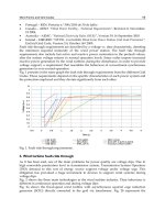
A method of frequency stabilization by using FESS
The main purpose of this study is to reduce the network frequency variation by using FESS.
The configuration of the control system for the frequency stabilization is shown in Fig. 7.
Reference of active power output of FESS, P
T(ref)
, is determined according to the deviation of
network frequency, which is detected by PLL at the terminal of FESS. When the frequency is
decreased, FESS supplies active power to the network. When the frequency is increased,
FESS absorbs active power from the network. These control schemes correspond to block
(A) in Fig. 7. At the same time, P
T(ref)
is modified to prevent a shortage or an excess of the
From Turbine to Wind Farms - Technical Requirements and Spin-Off Products
68
Reference Signal
Regulator
Rotor current
I
2D
, I
2Q
Active power P
T
Grid voltage V
T
Doubly-Fed Induction Machine (7MVA, 6.6kV, H=50.0)
Network frequency F
DC voltage
E
DC
Line current I
CD
, I
CQ
AC
DC
DC
AC
2.2kV / 6.6kV
Inverter
4.0kV
Converte
Reactive power Q
L
V
CD
’, V
CQ
’ V
2D
’, V
2Q
’
j0.08pu 0.005+j0.1pu
30% capacity of the system
Rotor speed W
R_FESS
P
T(ref)
Inverter
Controller
Converter
Controller
(A) (B)
DC link capacitor *1
*1 : Stored energy (J) is the rated power of the machine (W) × 0.02 (s).
abc-dq abc-dq
abc-dq
abc-dq
Fig. 3. FESS circuit configuration
stored energy of FESS. In this study, the maximum and the minimum rotor speeds of FESS
are specified 130% (1.3pu) and 70% (0.7pu) of the rated speed respectively. Considering
these boundary speeds, the value of P
T(ref)
is modified to a lower (or a higher) value when
the rotor speed is under (or over) 1.044pu, at which the stored energy becomes a half of the
maximum storage energy. These control schemes correspond to block (B) in Fig. 7. Fig. 7
also includes a rule of FESS control to avoid operating under 0.7pu or over 1.3pu rotor speed
as shown in Table I.
a
b
c
+
–
Fig. 4. Model of power converter
Frequency < 50 Frequency > 50
W
R_FESS
> 1.3 1 0
1.3 > W
R_FESS
> 0.7 1 1
0.7 > W
R_FESS
0 1
Table I. Rule of FESS control
Frequency Control of Isolated Power System with
Wind Farm by Using Flywheel Energy Storage System
69
s
20
8+
s
s
001.01
001.005.0
+
+
s
10
1+
I
2D
I
2Q
P
T
V
T
V
T(ref)
Reference Signal Regulator
W
R_FESS
F
V
2D
’
V
2Q
’
+
-
+
-
+
-
+
-
Phase compensator
s
80
8+
s
10
1+
s
s
001.01
001.005.0
+
+
P
T(ref)
Fig. 5. Output power controller of FESS
I
CD
I
CQ
E
DC
Q
L
Q
L(ref)
V
CD
’
V
CQ
’
+
-
+
-
+
-
+
-
Phase compensator
E
DC(ref)
s
20
2+
s
s
001.01
001.005.0
+
+
s
5
2.1+
s
20
2+
s
s
001.01
001.005.0
+
+
s
5
2.1+
Fig. 6. Excitation power controller of FESS
20
Table I
2.0
1.044
50.0
0.0
W
R_FESS
F
0
1
+
+
-
-
+
+
+
P
T(ref)
0 or 1
Base frequency
Half of
Storage
Energy
(A)
(B)
+
15.0
1
+s
11.0
15
+s
s
dead band
(-0.05 to +0.05)
1.05
-1.05
filter
derivative
P
T(prim)
Fig. 7. Reference signal controller for frequency stabilization
From Turbine to Wind Farms - Technical Requirements and Spin-Off Products
70
Wind farm model
The wind farm consists of an induction generator and a wind turbine. An aerodynamic
characteristic of the turbine blade expressed by eqs.( 2) and ( 3) is adopted [5]. The captured
power is expressed by eq.( 1). Since the induction generator is operated at almost constant
speed (approx. 1.0 to 1.01 pu), the output power changes widely with respect to wind speed
variations. Generally, a wind turbine is equipped with a pitch angle controller. The
conventional pitch controller shown in Fig. 8, that maintains the output of the generator to
be the rated power when the wind speed is over the rated speed, is also considered in this
study. Parameters of the wind generator (IG) are shown in Table II.
23
1
() [ ]
2
Mp W
PCRVW
ρλπ
=
(1)
20.17
( ) 0.5( 0.0.2 5.6)
p
Ce
λβ
−
Γ
=Γ− − (2)
3600
1609
R
λ
Γ= ⋅
(3)
s01.0
1
100 +
1.0
s51
1
+
PI
controller
Pitch
actuator
Rate limiter
(Max ±10/sec)
Active Power
+
–
Pitch
Angle β
Fig. 8. Pitch angle controller of wind turbine
IG FESS
Stator resistance (pu) 0.01 0.02
Stator leakage reactance (pu) 0.07 0.08
Magnetizing reactance (pu) 4.1 3.5
Rotor resistance (pu) 0.007 0.02
Rotor leakage reactance (pu) 0.07 0.08
Table II. Parameters of induction machines.
Synchronous generator model
A Synchronous Generator (SG) is considered as a main power supply unit in the network in
this study, which is assumed to be a diesel engine driven power plant. The characteristics of
the diesel engine and its governor system in [6] are considered. The governor controls fuel
supply to maintain the engine speed at the synchronous speed. Its block diagram is shown
in Fig. 9, and its parameters are shown in Table III.
Frequency Control of Isolated Power System with
Wind Farm by Using Flywheel Energy Storage System
71
If FESS regulates the network frequency by its power compensation, the output of SG may
not change, because the network frequency is controlled to be constant. Consequently, there
is a possibility that FESS performs all of the network frequency control instead of SG. In
such case, when the stored energy in FESS becomes full or empty, the power balance of the
network cannot be maintained and thus the network frequency can deviate significantly. To
avoid such situation, the output of SG also needs to be regulated according to the stored
energy of FESS. In this chapter, a cooperative control is proposed, in which the output of SG
is increased (or decreased) when the rotor speed of FESS is below (or over) 1.044pu which
corresponds to a half of the maximum storage energy of FESS. But if the additional
command to the main source generator changes fast, its output will also vary widely, and
then it suffers large mechanical stress. Therefore a control gain is set for the additional
command to change slowly as shown in Fig. 10. The governor of SG in this study has been
designed to control only engine speed, and thus the output of SG can be changed by
modifying a monitored signal of the engine speed to the governor. These control systems
are shown in Fig. 10. In addition, a simple AVR model shown in Fig. 11 is used in SG model.
Parameters of the synchronous generator (SG) are shown in Table IV.
P
K
s
K
I
sT
A
+1
1
sT
e
−
Actuator
Dead time of Engine
Output torque
w (Rotor speed)
w
ref
(Synchronous speed)
Controller
w
ex
(Additional signal for output adjustment)
Fig. 9. Governor model of the diesel engine
0.03
1.044
W
R_FESS
-
+
+
+
To SG governor
w
ex
0.02
130
2.1
+s
s
-0.02
Fig. 10. Additional signal controller for output adjustment of the diesel engine
From Turbine to Wind Farms - Technical Requirements and Spin-Off Products
72
11.0
10
+s
Terminal
Voltage
V
T0
(Reference) E
fd0
(Initial value)
Field voltage
E
fd
−
+
+
+
5
-5
11.0
1
+s
filter regulator
Fig. 11. AVR model of the synchronous generator
Proportional Gain of K
P
8.0
Integral Gain K
I
2.0
Pilot servo time constant T
A
0.2 s
Dead time of engine T 0.25 s
Table III. Parameters of the diesel engine governor
Armature resistance (pu) 0.0025
Stator leakage reactance (pu) 0.14
Field resistance (pu) 0.0004
Field leakage reactance (pu) 0.2
D-axis Q-axis
Magnetizing reactance (pu) 1.66 0.91
Damper resistance (pu) 0.005 0.0084
Damper leakage reactance (pu) 0.044 0.106
Table IV. Parameters of synchronous generator.
Frequency Control of Isolated Power System with
Wind Farm by Using Flywheel Energy Storage System
73
3. Simulation example
A. Condition
A determination of the energy storage capacity is very important for designing energy
storage system. In this chapter, the energy storage capacity of FESS is determined from a
point of view of adequate frequency control ability but reducing it as small as possible. The
power rating of FESS is decided as 70% of that of the wind farm since instantaneous output
change of the wind farm can hardly reach its power rating in normal operation.
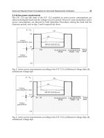
Comparative study between the proposed frequency control method (shown in Fig. 7 and
Table I) and a power smoothing method (shown in Fig. 12 and Table V) which is
generally considered in a wind farm connected to large power system, is performed in the
simulation analysis here. In conventional power smoothing method, an energy storage
system only smoothes wind farm output fluctuations, and slow change of wind farm
output is absorbed by several thermal and hydraulic power plants installed as main
generators in large power system. However, since the total power rating and the number
of main power generators are limited in the case of an isolated power system, power
regulation may become difficult even when wind farm output fluctuation is small.
Moreover, the output of main power generators should be adjusted also to maintain the
amount of residual energy of storage system. If the stored energy is not regulated
suitably, power balance of the isolated power system cannot be kept when the stored
energy reaches full or empty level. Therefore, it can be said that the frequency
stabilization in the case of an isolated power system cannot be achieved only by the
conventional power smoothing scheme.
Reference of
FESS output
power
Output of
wind generator
Low Pass Filter (1-order delay)
sT
D
+1
1
P
T(prim)
Fig. 12. Reference signal regulator of the FESS for power smoothing control
P
ref
< 0 P
ref
> 0
W
R_FESS
> 1.3 1 0
1.3 > W
R_FESS
> 0.7 1 1
0.7 > W
R_FESS
0 1
Table V. Rule of FESS control for power smoothing
From Turbine to Wind Farms - Technical Requirements and Spin-Off Products
74
0 100 200 300 400 500 600
0.7
0.8
0.9
1.0
1.1
0 100 200 300 400 500 600
200
300
400
0 100 200 300 400 500 600
-1.0
-0.5
0.0
0.5
1.0
0 100 200 300 400 500 600
0.0
0.5
1.0
0 100 200 300 400 500 600
49.6
49.8
50.0
50.2
50.4
0 100 200 300 400 500 600
4
8
12
16
Mechanichal torque of
the diesel engine (pu)
Time (s)
Power smoothing method
Frequency control method
Stored energy o
f
the FESS (MJ)
(Min:122.5, Mid:250, Max:422.5)
Time (s)
Power smoothing method
Frequency control method
Power output of
the FESS (pu)
Time (s)
Power smoothing method
Frequency control method
Wind generator output (pu)
Wind farm output (pu)
Time (s)
Wind generator output
Wind farm output (frequency control method)
wind farm output (power smoothing method)
Frequency of
the power system (Hz)
Time (s)
Power smoothing method
Frequency control method
Wind speed (m/s)
Time (s)
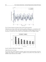
Fig. 13. System response under the frequency control method and power smoothing method
Frequency Control of Isolated Power System with
Wind Farm by Using Flywheel Energy Storage System
75
In the comparative study, simulations by the conventional output power smoothing method
have also been performed, in which the reference output from the WF to the grid is
determined by inputting the net WF output into a first order delay transfer function and
FESS supply the difference between the reference power and the net output to follow the
WF-to-grid output to the reference value as shown in Fig. 12. Therefore block A in Fig. 7 is
replaced by Fig. 12 and the rule of FESS control shown in Table I is also replaced by Table
V. In the conventional method, the cooperation control with the main power plant is
impossible. The power rating of FESS is chosen to be 7MVA, same as that in the frequency
control method, and the time constant of the first order delay is set to 30s.
B. Results
Fig. 13 shows system responses under the proposed frequency control method and the
conventional power smoothing method. The frequency deviation reaches about 0.3Hz at the
maximum in the case of the power smoothing method, but it is regulated within about
0.05Hz in the case of the frequency control method. The stored energy of FESS is remained
well between the maximum and the minimum levels, from which there may be a possibility
that the energy storage capacity of FESS can be reduced. Responses of the prime mover
output (diesel engine output) are almost the same in both methods.
4. Summary
This chapter has proposed a new method of network frequency regulation by using
Flywheel Energy Storage System (FESS) for an isolated power system including a wind
farm, and the validity of the proposed method has been evaluated by computer simulations.
From the comparative study between the proposed method and the conventional output
smoothing control of wind farm, it has been shown that the proposed method is very
effective on the stabilization of network frequency in an isolated small power system.
The proposed method can be applied basically not only to a FESS system but also other
types of energy storage system. Therefore the proposed method can contribute to expand
wind energy utilization into isolated power systems like a small island.
5. References
[1] T. Kuwabara, A. Shibuya, H. Furuta, E. Kita, and K. Mitsuhashi : "Design and Dynamic
Response Characteristics of 400 MW Adjustable Speed Pumped Storage Unit for
Ohkawachi Power Station," IEEE Transactions on Energy Conversion, Vol. 11, No.
2, pp. 376-384, June 1996.
[2] M. Kazuma, U. Yuuetsu : "Hydroelectric Power Technologies Contributing to Power
System Quality Improvement", TOSHIBA REVIEW, VOL.58, NO.7, 2003.
[3] Manitoba HVDC Research Centre (
[4] R.Takahashi, J.Tamura, Y.Tada, A.Kurita: "Model Derivation of an Adjustable Speed
Generator and Its Excitation Control System", Proc. of 14-th Power System
Computation Conference, Session-06, paper-4, June 2002.
[5] O. Wasynczuk, D. T. Man, J. P. Sullivan : "Dynamic Behavior of a Class of Wind Turbine
Generator During Random Wind Fluctuations", Trans. of IEEE on Power
Apparatus and Systems, Vol. PAS-100, No.6, pp.2873-2845, June 1981.
From Turbine to Wind Farms - Technical Requirements and Spin-Off Products
76
[6] Sanjoy Roy, O.P.Malik, G.S.Hope : "A k-Step Predictive Scheme for Speed Control of
Diesel Driven Power Plants", IEEE Transactions on Industry Applications, Vol. 29,
No. 2, pp. 389-396, March/April 1993.
5
Control Scheme of Hybrid Wind-Diesel
Power Generation System
Cuk Supriyadi A.N
1
, Takuhei Hashiguchi
1
, Tadahiro Goda
1
and Tumiran
2
1
Graduate School of Information Science and Electrical Engineering,
Kyushu University, Fukuoka, 819-0395
2
Department of Electrical and Information Technology
Faculty of Engineering, Gadjah Mada University, Yogyakarta,55281
1
Japan
2
Indonesia
1. Introduction
Global warming is one of the most serious enviromental problems facing the world
community today. It is typified by increasing the average temperature of Earth's surface and
extremes of weather both hot and cold. Therefore, implementing a smart and renewable
energies such as wind power, photo voltaic etc are expected to deeply reduce heat-trapping
emissions. Moreover, wind power is expected to be economically attractive when the wind
speed of the proposed site is considerable for electrical generation and electric energy is not
easily available from the grid (Ackermann, 2005). This situation is usually found on islands
and/or in remote localities. However, wind power is intermittent due to worst case weather
conditions such as an extended period of overcast skies or when there is no wind for several
weeks. As a result, wind power generation is variable and unpredictable.
The hybrid wind power with diesel generation has been suggested (Hunter, 1994) and
(Lipman, 1989) to handle the problem above. A hybrid wind diesel system is very reliable
because the diesel acts as a cushion to take care of variation in wind speed and would
always maintain an average power equal to the set point. However, in addition to the
unsteady nature of wind, another serious problem faced by the isolated power generation is
the frequent change in load demands. This may cause large and severe oscillation of power.
The fluctuation of output power of such renewable sources may cause a serious problem of
frequency and voltage fluctuation of the grid, especially, in the case of isolated microgrid,
which is the a small power supply network consisting of some renewable sources and loads.
In the worst case, the system may lose stability if the system frequency can not be
maintained in the acceptable range.
Control schemes to enhance stability in a hybrid wind – diesel power system have been
proposed by much researchers in the previous work. The programmed pitch controller (PPC)
in the wind side can be expected to be a cost-effective device for reducing frequency deviation
(Bhatti et. al ,1997) and (Das et. al, 1999). Nevertheless, under the sudden change of load
demands and random wind power input, the pitch controller of the wind side and the
governor of the diesel side may no longer be able to effectively control the system frequency
due to theirs slow response. To overcome this problem, an Energy Storage (ES), which is able
From Turbine to Wind Farms - Technical Requirements and Spin-Off Products
78
to supply and absorb active power rapidly, has been highly expected as one of the most
effective controller of system frequency (Tripathy et. al. 1997) and (Tripathy et. al. 1997).
In this chapter, Superconducting Magnetic Energy Storage (SMES) is used as Energy Storage.
It is able to compensate the fluctuation of wind power generation. The SMES unit is a device
that stores energy in the magnetic field generated by the direct currents flowing through a
superconducting coil. Since energy is stored as a circulating current, energy can be drawn from
the SMES unit with almost instantaneous response with energy stored or delivered over
periods ranging from a fraction of a second to several hours (Ribeiro et.al, 2001). Because direct
current flows with negligible losses in superconductors, the SMES unit can be used for small
and large scale energy storage and rapid charge/discharge applications. The SMES system
consists of a large superconducting coil at the cryogenic temperature. The coil is kept at
cryogenic (superconductive) temperature by a refrigeration system designed to meet the
superconducting properties of the special materials used to fabricate the magnetic coil. A
power conversion/conditioning system connects the SMES unit to an ac power system, which
has an inverter that converts the dc output of the storage device to ac during discharge and the
ac to dc for recharging the storage device (Schainker, 2004).
The SMES systems have several advantages. The SMES coil has the ability to release large
quantities of power within a fraction of a cycle, and then fully recharge in just minutes. The
SMES unit can store and discharge DC power at efficiencies of 98% or more and switch
between charging and discharging within 17 milliseconds. This quick, high-power response
is very efficient and economical. The SMES manufacturers cite controllability, reliability and
no degradation in performance over the life of the system as prime advantages of SMES
systems. The estimated life of a typical system is at least 20 years (Schainker, 2004).
In power system, the SMES is capable of supplying both active and reactive powers
simultaneously and quickly. Thus, it is able to enhance the power system stability and
reliability dramatically (Jiang & Chu, 2001) and (Simo& Kamwa, 1995). Primarily, the SMES
unit was aimed to store energy during the off-peak load period and release it in the peak
load period. It has been shown that the SMES is able to supply the active and reactive power
simultaneously and damp the oscillations in an power system (Simo& Kamwa, 1995) and
(Wu & Lee, 1993). In fact, the SMES can also be used as a PSS, if the control scheme is
suitably designed (maschowski & Nelles, 1992). Besides, the applications of the SMES also
include load regulation, transmission stabilization, uninterruptible power supply, power
compensation, voltage control and improving customer power quality, etc. (Buckles &
Hassenzahl, 2000). Moreover, the SMES also has been successfully applied to solve many
problems in power systems such as an improvement of power system dynamics (Rabbani
et.al., 1998) and (Devotta & Rabbani,2000), a frequency control in interconnected power
systems (tripathy,1997) and (Ngamroo,2005), an improvement of power quality (Chu et.al.
2001), a stabilization of sub-synchronous oscillation in the turbine-generator (Devotta et.al.
1999), a load leveling (Abdelsalam et.al. 1987) etc.
Several design methods to design SMES have been successfully proposed, such as a
proportional control (Banerjee et.al. 1990), a digital control (Tripathy & Juengst, 1997), an
adaptive control (Tripathy et.al. 1997), a neural network (Demiroren et.al. 2003) and a fuzzy
control (Demiroren & Yesil 2004), etc. Despite the potential of modern control techniques
with different structures, power system utilities still prefer the fixed structure controller. The
reasons behind that might be the ease of on-line tuning and the lack of the assurance of
stability related to some adaptive or variable structure techniques. On the other hand,
various generating and loading conditions, wind power fluctuations, variation of system