báo cáo hóa học:" Comparison of transverse wires and half pins in Taylor Spatial Frame: A biomechanical study" pdf
Bạn đang xem bản rút gọn của tài liệu. Xem và tải ngay bản đầy đủ của tài liệu tại đây (641.76 KB, 7 trang )
RESEARC H ARTIC L E Open Access
Comparison of transverse wires and half pins in
Taylor Spatial Frame: A biomechanical study
Ashish Khurana
1*†
, Carlton Byrne
2†
, Sam Evans
2†
, Hiro Tanaka
3†
, Kartik Haraharan
3†
Abstract
Background: The aim of this study was to compare the stiffness characteristics of Taylor Spatial Frame (TSF) fixed
with transverse wires and half pins.
Design & Methods: Experiments were carried out at the biomechanics laboratory at Cardiff University. All
mechanical testing was performed with a servo hydraulic test frame (MTS 858 Mini Bionix II(R), MTS Corp.,
Mineapolis, USA). Custom built mounts were used to attach the bone rigidly to the one end of machine and the
TSF ring to the other. Rings were fixed with 1.8 mm transverse wires or hydroxy-apatite coated 6.5 mm half pins in
45degrees, 60degrees, 75degrees and 90degrees divergence angles. Bone was loaded with axial load to 400 N and
torque to 20 Nm in an indestructible manner. Load/displacement curve data were analyzed for slope and axial and
angular displacements.
Results: For larger diameter rings (180 mm), for axial stiffness there was no statistically significant difference
between the transverse wires (4 wires with 2 rings) and the half pins (2 pins with 1 ring) (p > 0.05). For 155 mm
internal diameter rings, half pins provided statistically higher axial stiffness than transverse wires (p = 0.036). The
half pins show significantly more torsion stiffness in both ring diameters (p < 0.05) in comparison to transverse
wires. As in axial stiffness, small diameter rings show increased stiffness in torsion. There is increase in axial and
torsion stiffness with the increase in the divergence angle between the wires or pins (p < 0.05).
Conclusion & Clinical Relevance: Half pins provide greater stiffness to TSF frames and allow for axial micro
motion as well. This work provides a rationale for clinical decision making about the use of tensioned transverse
wires in comparison to half pins in construction of a TSF frame
Background
The Taylor Spatial Frame (TSF; Smith & Nephew,
Memphis, Tennessee) is an advanced orthopaedic mod-
ality based on a Stewart platform [1]. It is used to treat
fractures and correct deformities via an external hexa-
pod fixator that combines ease of application plus com-
puter accuracy[1].
Although TSF is a form of ring fixator, the principles
of deformity correction and the material chara cteristics
of the construction are entirely different to the other
ring fixators available to Orthopaedic community. Tradi-
tionally the ring fixators have b een constructed using
transverse wires. Transverse wires can cause damage to
nerves and blood vessels. Impalement of muscles is
often a complication from this technique[2]. In compari-
son, half pins are safer and easier to apply. The ring
fixators work on the p rinciple of allowing axial m icro-
motion with weight bearing which is considered to
encourage bone he aling[3,4]. The construct of the frame
should be sufficiently stiff so as to hold the fracture
reduction. On the other hand i t requires a fine balance
to allow s ome axial micromotion betw een the fracture
ends to enhance fracture healing.
Thereislittledataoncomparativebiomechanicsof
half pins and transverse wires as fixation elements in
the TSF. There are some stud ies in literature evaluating
the clinical outcome of TSF[5], but there are none eval-
uating the biomechanics of TSF.
The aim of this study was to compare the axial and
torsion biomechanics of TSF rings fixed with half pins
and transverse wires. This study was designed to address
the following research questions:
* Correspondence:
† Contributed equally
1
Department of Trauma & Orthopaedics, University Hospital of Wales, Heath
Park, Cardiff, UK
Khurana et al. Journal of Orthopaedic Surgery and Research 2010, 5:23
/>© 2010 Khurana et al; licen see BioMed Central Ltd. This is an Open Access a rticle distributed under the terms of the Creative Commons
Attribution License (http://creative commons.org/licenses/by/2.0), which permits unrestri cted use, distribution, and reproduction in
any medium, provided the original work is properly cited.
1)Comparison of axial and t orsional stiffness charac-
teristics of TSF with half pins and transverse wires.
2)Variation of the stiffness characteristics with varia-
tion in the divergence angle from 45 to 90 degrees for
both wires and half pins
3)Var iation of the stiffness characteristics with change
of ring size from 155 mm to 180 mm internal diameter.
Materials and methods
The experiments were carried out at the Biomechanics
laboratory, School of Engineering, Cardiff Univers ity. All
mechanical testing was performed with a servo hydraulic
test frame (MTS 858 Mini Bionix II®, MTS Corp., Min-
neapolis, USA).
Custom built mounts were used to attach bone rigidly
to the top end of the machine. Cadaver calf tibiae were
used for the experiments. Bone was fixed into the
mount using centrali sing bolts (figure 1). To avoid point
application of force and to prevent any toggle on force
application,thefreespacearoundtheboneinthe
mount was filled with a polymer filler. This provided an
absolute rigid fixation of bone to the mount.
TSF ring was attached using anothe r custom built
mount to the other end of the testing machine. The
mount used to hold th e rings had modularity to enable
attachment of different size rings. Rings were fixed with
1.8 mm transverse wires or hydroxy-apatite coated 6.5
mm half pins. Half pins were inserted after predrilling.
Test s were performed with the wires or pins in 45°, 60°,
75° and 90° intersection angles. All t ests were also
repeated with 2 ring sizes: 155 and 180 mm internal
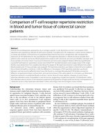
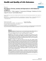
diameter. Figure 2 shows a typical test s et up with the
MTS test frame using transverse wires.
Transverse wires used were 1.8 mm stainless steel
wires, tensioned to 110 kg. A standard calibrated dyna-
mometric tensioning device (Smith & Nephew, Mem-
phis, Tennessee) was used for tensioning the transverse
wires. Tests were also performed with an additional ring
mounted with 2 transverse wires, as is common in clini-
cal practice. These 2 rings, mounted with 2 wires each,
were connected to each other with rods and acted as a
single assembly. For tests using half pins, 6.5 mm (sec-
tion diameter) hydroxy-apatite coated half-pins were
fixed onto the rings using rancho cubes. Half pins were
inserted bi-cortically. The wires or pins crossed in the
centre of tibia and the tibia was positioned in the centre
of the ring. New wires were used for all experiments.
Half pins were replaced only if there was any visible
deformation in them.
Component variables evaluated were ring diameter
(155 mm and 180 mm) and wire or pin divergence
angle (45 degrees, 60 degrees, 75 degrees and
90 degrees). This resulted in 24 constructs based on 2
ring sizes, 4 divergence angles and 3 configurations
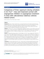
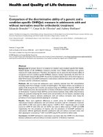
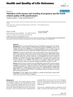
Figure 1 A typical test setup suing h alf pins. The bone is held
by the mount at the top end of the test frame and the ring is held
rigidly by the bottom end of the frame. The weakest link in the
setup is wires or pins connecting the bone to the rings. When load
is applied to the bone from the top end it will displace depending
on how rigidly it is held by wires or pins.
Figure 2 A typical test setup using transverse wires.
Khurana et al. Journal of Orthopaedic Surgery and Research 2010, 5:23
/>Page 2 of 7
(half pins, 1 ring fixed with 2 transverse wires and 2
rings fixed with 2 trans verse wires each). Each construct
was evaluated for axial and torsional biomechanics . The
tests were repeated thrice on each fixation and the
results were averaged. Experi ments were performed in a
random sequence.
Based on the literature rev iew [5-9] and to apply loads
in the clinical range, the bone was loaded with axial
load to 400 N and torque to 20 Nm in an indestructible
manner. Axial load was applied over 60 seconds and
5 mm displacement was set as the maximum permissi-
ble displacement. Similarly, torque was applied over a
period of 60 seconds with 30 degree angular displace-
ment as the maximum limit. Torsional stiffness was
tested without any coupled axial preload.
Main Outcome measures: axial and angular deforma-
tion characteristics as a result of axial and rotational
(torque)loadrespectivelywerecomparedforthe
described constructs. Displacement of the bone in rela-
tion to the pre - load position was recorded by the MTS
test frame. Load/displacement data was obtained for
each individual ring fixation and the curves were ana-
lyzed for slope, axial and angular displacements. The
slope of the regression line of these average data points
is defined as the stiffness (load/deformation). Stiffness
values for various fixations were compared. Data was
stored using excel and was analysed on SPSS software
(Version 14, SPSS Inc. Chicago,Il).Thedatawereana-
lysed using an analysis of variance (ANOVA) and indivi-
dual differences were d etermined using a post hoc test.
Students t test was used to compare the corresponding
stiffnessvaluesofringsfixedwithhalfpinsandtrans-
verse wires between two specific groups. A p value of ≤
0.05 was considered to be significant.
Results
Axial Stiffness
Stiffness was calculated from load displacement curve by
linear regression between 250 and 300 N loading. This
provided an intermittent linear portion in the curve[6]
which corresponds to the clinical range of loads applied
to the lower limb bones on weight bearing. As described
earlier, tests were carried out on ring constructs made
using 2 half pins in comparison to those constructed
using transverse wires. Use of one ring in transverse
wire construct was also compared with a 2 ring con-
structs using transverse wires (with an accessory ring).
Structural failure was not observed in any specimen.
A non linear load displacement behaviour was observed
for all specimens in the test range.
Table 1 shows the comparative axial stiffness of TSF
rings fixed with transverse wires and half pins in varying
divergent angles. The increase in stiffness between a
transverse wire (with accessory ring) construct and a
half pin construct ranged from 20.4% to 50%. The stiff-
ness of the fixation increased with increasing intersec-
tion angle between the wires or pins. This was true for
both wires and the pins. Constructs with divergent angle
of 90 degree were found to be most stiff in both the ring
diameters (p < 0.05) (table 1).
Force required to produce 1 mm d isplacement was
also analysed for all the configurations. This reflects
clinically important range of displacements and the
associated fixato r stiffness[6]. Results are as per table 2.
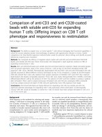
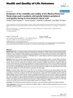
Figures 3a and 3b compare the axial stiffness in varying
divergence angles, as shown in Table 1.
Torsional Stiffness
Torsional stiffness (table 3) was calculated as regression
from the torsional moment and angulation data between
4 and 7 Nm torque. This was calculated as slope of the
graph obtained between torsion load and angular
displacement.
Discussion
This study suggests that the transverse wires (with
accessory ring) and half pins provide comparable axial
stiffness for 180 mm rings. Based on Table 1 , for all
respective divergence angles, there is no statistically sig-
nificant difference between the stiffness of half pins and
transverse wires (with accessory rings) for 180 mm
rings. As per Table 1, the axial stiffness of a ring fixed
Table 1 Axial stiffness of rings
180 mm rings 155 mm rings
Divergence Angle Half pins
(1 ring)
Transverse Wires
(2 rings)
Transverse Wires
(1 ring)
Half pins
(1 ring)
Transverse Wires
(2 rings)
Transverse Wires
(1 ring)
90° 98.04 (±2.03) 102.04 (±1.28) 68.49 (±0.39) 200 (±2.61) 138.88 (±2.08) 80.64 (±0.33)
75° 89.28 (±2.37) 90.59 (±1.85) 67.56 (±0.83) 192.3 (±1.27) 128.2 (±1.15) 78.12 (±1.93)
60° 74.62 (±1.46) 79.36 (±2.76) 52.08 (±2.18) 151.51 (±0.19) 125 (±0.08) 79.36 (±2.81)
45° 63.29 (±0.37) 65.44 (±2.31) 51.02 (±1.49) 116.27 (±1.68) 92.59 (±1.27) 83.33 (±2.89)
All values in N/mm and brackets show SD. For larger diameter rings (180 mm) there was no statistically significant difference between the transvers e wires (with
accessory ring) and the half pins (p > 0.05). Both, half pin and transverse wires constructs with accessory rings were significantly stiffer than a single ring fixation
using 2 transverse wires only (p = 0.017). For 155 mm internal diameter rings, half pins provided statistically higher axial stiffness than transverse wires with
accessory rings (p = 0.036).
Khurana et al. Journal of Orthopaedic Surgery and Research 2010, 5:23
/>Page 3 of 7
Table 2 Force for 1 mm displacement
180 mm rings 155 mm rings
Divergence Angle Half pins (1 ring) Transverse Wires (2 rings) Half pins (1 ring) Transverse Wires (2 rings)
90° 188.1 (±3.27) 198.8 (±1.46) 209 (±0.35) 195.5 (±1.63)
75° 169.19 (±1.77) 173.46 (±2.49) 204 (±3.18) 184.3 (±3.51)
60° 149.77 (±1.39) 155.66 (±2.83) 178.8 (±2.67) 178.8 (±1.35)
45° 129.35 (±0.78) 124.37 (±3.71) 164.4 (±1.93) 150.1 (±2.47)
All values in N and brackets show SD. There was no statistically significant difference between the half pin and transverse wires (with accessory ring) assembly
(p > 0.05). However, there was a significant increase in force required to allow 1 mm movement in the smaller (155 mm) ring size (p = 0.038).
Figure 3 a: Axial stiffness of 180 mm rings. b: Axial stiffness of 155 mm rings. c: Torsion stiffness (180 mm rings). d: Torsion stiffness 155 mm
rings.
Table 3 Torsion stiffness
180 mm rings 155 mm rings
Divergence Angle: Half pins
(1 ring)
Transverse Wires
(2 rings)
Transverse Wires
(1 ring)
Half pins
(1 ring)
Transverse Wires
(2 rings)
Transverse Wires
(1 ring)
90° 2.67 (±0.12) 2.11 (±0.05) 0.49 (±0.04) 2.94 (±0.07) 2.63 (±0.08) 0.60 (±0.04)
75° 2.36 (±0.07) 2.09 (±0.09) 0.46 (±0.06) 2.67 (±0.10) 2.17 (±0.11) 0.51 (±0.03)
60° 2.09 (±0.08) 1.91 (±0.11) 0.35 (±0.02) 2.63 (±0.04) 2.11 (±0.04) 0.51 (±0.07)
45° 2.04 (±0.10) 1.84 (±0.08) 0.34 (±0.05) 2.11 (±0.05) 2.09 (±0.07) 0.45 (±0.06)
All values in Nm/deg and brackets show SD. The half pins show significantly more torsion stiffness in both ring diameters (p < 0.05) in comparison to transverse
wires. There is increase in stiffness with the increase in the d ivergence angle as well (p = 0.048). As in axial stiffness, small diameter rings show increased
stiffness in torsion. Single ring fixation with transverse wires (without any accessory rings) provides significantly weak construct in both ring diameters and all
divergence angles (p = 0.008). For 180 mm rings, the torsion stiffness of half pins construct is between 9.4% to 26.5% more than the transverse wires (with
accessory ring) construct. Similarly, for 155 mm diameter rings, there was an increase between 9.5% and 24.6% for half pins in comparison to transverse wires
(with accessory ring) construct.
Khurana et al. Journal of Orthopaedic Surgery and Research 2010, 5:23
/>Page 4 of 7
with half pins in 90 degrees is 98.04 ± 2.0 N/mm and
that with wires was 102.04 ± 1.3 N/mm. In clinical prac-
tice, because of anatomical constr aints it is not possible
to fix a ring with wires crossing at 90 degrees. But it is
possible to put pins in 90 degrees. The maximum angle
ofwiresdivergenceis60degrees in clinical practice
[2,5,10,11]. Stiffness achieved with this construct was
79.36 ± 2.8 N/mm, when using an accessory ring. There
was a significant differencewhenthisiscomparedto
half pins in 90 degrees (i.e. 98.04 ± 2.0 N /mm)
(p = 0.028). He nce, the versatility and modularity of half
pin system enables to achieve stiffness more than that
possible with a transverse wires construct. The axial
stiffness provided by transverse wires using a single ring
is statistically much inferior to either of the other con-
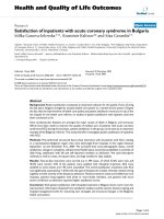
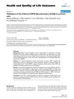
structs. Figures 4a-b show the typical load displacement
curves for the three configurations with divergence
angle of 90 degree.
Though the pins provide comp arable or more stiffness
than transverse wires, they allow some axial movements as
well. As shown in Table 2, 209 ± 0.4 N and 188.1 ± 3.3 N
load was required to produce 1 mm axial movement with
half pins fixation at 90 degree in 155 and 180 mm rings
respectively. This load is in clinical range and is applied on
weight bearing. Hence, pin fixation can also provide axial
micromotion similar to that seen in transverse wires.
The half pins show significantly more t orsion stiffness
in both ring diameters (p < 0.05) in comparison to
transverse wires as shown in Table 3 and figures 3c and
3d. There is an inc rease in stiffness with the i ncrease in
the divergence angle as well, which was statistically sig-
nificant (p < 0.05).
Table 1 and 2 show a progressive increase in axial
stiffness with increase in divergence angles for both
sized rings. This is true for both half pins as well as the
transverse wires. Similar increase in tors ional stiffness is
also seen as demonstrated in Table 3. Podolsky and
Chao[12] concluded the same for axial stiffness in their
experiments. However they also concluded that fixators
with wires crossing at 45 had significantly greater stiff-
ness in torsion compared to those with 90 deg crossing
wires. In the experiments by Roberts et al, a consider-
able reduction in the axial and torsion stiffness with
decreasing wire divergence angle was observed[5]. Our
findings match that of both these authors with regard to
axial stiffness. However, in our tests the torsional stiff-
ness also increased with increasing divergent angles, for
both transverse wires and the half pins. These are in
conformity with Roberts et al[5].
When the ring size is decreased to 155 mm the axial
stiffness of the half pin construct is significantly more
than the transverse wires construct (with an accessory
ring). With smaller ring size, half pins are significantly
stiffer than transverse wires (with accessory ring),
whereas with larger diameter the two were comparable
as demonstrated in Table 1, 2, 3. Further evaluation of
effects of ring size over a broad spectrum may be war-
ranted before any definite conclusions could be drawn.
But the current results lead to a hypothesis that pins
may loose relative stiffness benefits in larger ring sizes
and hence should be avoided for obese subjects, which
require larger ring sizes. This is due to increase in the
bending moment of the half pins, which act as cantilever
beams, in larger rings. This may increase the stresses at
the pin bone interface, leading to pin loosening and
decreased stiffness. Ring diameter has been shown to
have significant effect on stiffness[6,13-15]. Unfortu-
nately the ring diameter is dictated by the size of the
patient and the smallest diameter sho uld be used giving
adequate clearance to soft tissues[16]. Decrease of the
construct stiffness with increase in ring diameter is attri-
butable to the fact that deflec tion of a wire subjected to
a specific load is dependant in pa rt on functional length
of the wire[6,12,14].
Wire tension is a major influence on the stiffness of
ring fixators[17]. In this study new wires were used for
each test. In clinical practice, there is more p robability
of wires going loose, leading to loss of stiffness[17].
Figure 4 a-b: Load displacement curves for the three
configurations with axial and torsion loading (with divergence
angle 90 degree and 155 mm TSF ring).
Khurana et al. Journal of Orthopaedic Surgery and Research 2010, 5:23
/>Page 5 of 7
Half pins do not need tensioning and with decreasing
incidence of infection with surgical care and hydroxy-
apatite coating[18,19] stiffness of a pin based fixator
would be expected to be maintained during clinical use.
There are some studies in literature evaluating the
clinical outcome of TSF[20-22], but there are none eval-
uating the biomechanics of TSF. Amongst biomechani-
cal studies on other ring fixators, all but one study
found in English literature are based on frames[5]. This
does not eliminate the confounding effects of frame
assembly, connecting struts or rods, ring spacing and
the interface characteristics of fixation elements used for
multiple rings[5]. The design in our study was estab-
lished so as to evaluate only wire and pin behaviour as
fixation elements in TSF with elimination of other con-
founding variables. In our experiments, bone was r igidly
attached to one end and the ring was attached to the
bot tom end of the MTS frame. The set up ensured that
the o nly weak link in the assembly was the wire or half
pin connection between the ring and the bone.
It is very difficult to compare the results of different
studies on ring fixators because not only the fixator con-
struction characteristics but also the loading modes are
usually different[8]. The difference in the results of var-
ious researchers in the biomechanics of ring fixators can
be attributed to difference in the modality of their tests.
It can be difficult to appropriately determine construct
stiffness for non linear behaviour. The data can be trans-
formed logrythmatically to determine stiffness at multiple
points along the load displacement curve with an
assumption of linearity at each point[12,13]. The stiffness
can also be determined at intermittent or terminal linear
portions of the graph[6]. Cross et al observed that this
may bias the data towards higher stiffness values but pro-
vides a valid means of comparison between constructs[6].
In this study, stiffness was calculated from load displace-
ment curve b y linear regression between 250 and 300 N
loading. Windhagen et al used a similar methodology but
a different range (300 to 35 0 N) [9]. 250 to 300 N load
was used for analysis in this study as we believed that this
corresponds closely to the loads applied on the lower
limbs on weight bearing.
Limitations and further research
This study had some potential limitations. All tests were
performed on calf bones. There could be a difference
between the biomechanical characteristics of human and
calf bones. Orienti has concluded from his work that
the in vitro model does not realistically simulate the
behaviour of external fixation pins implant ed in ex-vivo
bone[23]. The cadaver ic bones may also have anthropo-
metric variations. An attempt to decrease this effect was
made by obtaining the bones from same aged cadaveric
calf from a single population. All experiments were
repeated thrice and were perf ormed in a random o rder
to compensate for any variation.
New transv erse wires were used for all tests. However
the same half pins were repeatedly used to limit the
costs. They were discarded only if any damage was
obvious. This may affect the results to some extent.
Random order of tests and repetition of tests decreased
the bias in the results.
The stiffness was tested under experimental conditions
and the bone was centrally fixed within the ring. In clin-
ical practice this may often not be possible due the bone
shape and the surrounding soft tissues. Podolsky and
Chao illustrated that eccentric placement of bone within
the rings has no adverse effects[12]. The authors also
believe that with rigid fixation of the bone wit h the
MTS frame, the constructs were constrained so that the
bone could not move sideways under axial loading. This
affected the half pin constructs more than the wire con-
structs since they are not symmetrical, creating a bias in
favour of the half pins.
Only axial and torsional stiffness was tested in our
study. These two are the most crucial forces acting on
the lower limb fixators. Bending stiffness is more depen-
dant on the connecting rods/struts between the rings
rather than the fixation elements like transverse wires
and half pins. Moreover, tests for evaluating bending
stiffness were not possible on the available MTS 858
Mini Bionix machine.
Torsional stiffness was tested without any coupled
axial preload. Further work can be performed to analyse
the torsional stiffness characteristics with applied a xial
preloads to simulate weight bearing along with torsional
stress.
These experiments were performed in a controlled
manner and pr ovide an estimate of stiffness. Bone load-
ing during mobilisation and physiological conditions can
be eccentric and combination of various forces. The
study has not evaluated the biomechanics of the com-
bined use of half pins and transverses wires in a hybrid
frame. This work provides a rationale for clinical deci-
sion making about the use of tensioned transv erse wires
in comparison to half pins in construction of a TSF
frame.
Acknowledgements
The authors would like to thank Smith and Nephew for providing the
implants for performing the experiments.
Author details
1
Department of Trauma & Orthopaedics, University Hospital of Wales, Heath
Park, Cardiff, UK.
2
School of Engineering, Cardiff University, Cardiff, UK.
3
Department of Trauma & Orthopaedics, Royal Gwent Hospital, Newport, UK.
Authors’ contributions
AK coordinated the study, carried out the experiments, analysed the result
and drafted the manuscript. CB and SE designed the setup and helped to
Khurana et al. Journal of Orthopaedic Surgery and Research 2010, 5:23
/>Page 6 of 7
perform the tests. HT & KH conceptualised the study, analysed the results
and helped to draft the manuscript. All authors read and approved the final
manuscript.
Competing interests
The authors declare that they have no competing interests.
Received: 4 May 2009 Accepted: 27 March 2010
Published: 27 March 2010
References
1. Al-Sayyad MJ: Taylor Spatial Frame in the treatment of pediatric and
adolescent tibial shaft fractures. J Pediatr Orthop 2006, 26:164-70.
2. Oh JK, Lee JJ, Jung DY, Kim BJ, Oh CW: Hybrid external fixation of distal
tibial fractures: new strategy to place pins and wires without
penetrating the anterior compartment. Arch Orthop Trauma Surg 2004,
124:542-6.
3. Claes L, Eckert-Hübner K, Augat P: The effect of mechanical stability on
local vascularization and tissue differentiation in callus healing. J Orthop
Res 2002, 20:1099-105.
4. Yamaji T, Ando K, Wolf S, Augat P, Claes L: The effect of micro movement
on callus formation. J Orthop Sci 2001, 6:571-5.
5. Roberts CS, Antoci V, Antoci V Jr, Voor MJ: The effect of transfixion wire
crossing angle on the stiffness of fine wire external fixation: a
biomechanical study. Injury 2005, 36:1107-12.
6. Cross AR, Lewis DD, Murphy ST, Rigaud S, Madison JB, Kehoe MM,
Rapoff AJ: Effects of ring diameter and wire tension on the axial
biomechanics of four-ring circular external skeletal fixator constructs. Am
J Vet Res 2001, 62:1025-30.
7. Yilmaz E, Belhan O, Karakurt L, Arslan N, Serin E: Mechanical performance
of hybrid Ilizarov external fixator in comparison with Ilizarov circular
external fixator. Clin Biomech (Bristol, Avon) 2003, 18:518-22.
8. Yang L, Nayagam S, Saleh M: Stiffness characteristics and inter-
fragmentary displacements with different hybrid external fixators. Clin
Biomech (Bristol, Avon) 2003, 18:166-72.
9. Windhagen H, Glöckner R, Bail H, Kolbeck S, Raschke M: Stiffness
characteristics of composite hybrid external fixators. Clin Orthop Relat Res
2002, 405:267-76.
10. Green SA: Ilizarov external fixation. Technical and anatomic
considerations. Bull Hosp Jt Dis Orthop Inst 1988, 48:28-35.
11. Antoci V, Raney EM, Antoci V Jr, Voor MJ, Roberts CS: Transfixion wire
positioning within the bone: an option to control proximal tibia external
fixation stiffness. J Pediatr Orthop 2006, 26:466-70.
12. Podolsky A, Chao EY: Mechanical performance of Ilizarov circular external
fixators in comparison with other external fixators. Clin Orthop Relat Res
1993, 293:61-70.
13. Gasser B, Boman B, Wyder D, Schneider E: Stiffness characteristics of the
circular Ilizarov device as opposed to conventional external fixators. J
Biomech Eng 1990, 112:15-21.
14. Lewis DD, Bronson DG, Cross AR, Welch RD, Kubilis PS: Axial characteristics
of circular external skeletal fixator single ring constructs.
Vet Surg 2001,
30:386-94.
15. Lewis DD, Bronson DG, Samchukov ML, Welch RD, Stallings JT:
Biomechanics of circular external skeletal fixation. Vet Surg 1998,
27:454-64.
16. Ilizarov GA: The tension-stress effect on the genesis and growth of
tissues. Part I. The influence of stability of fixation and soft-tissue
preservation. Clin Orthop Relat Res 1989, 238:249-81.
17. Hillard PJ, Harrison AJ, Atkins RM: The yielding of tensioned fine wires in
the Ilizarov frame. Proc Inst Mech Eng [H] 1998, 212:37-47.
18. Moroni A, Heikkila J, Magyar G, Toksvig-Larsen S, Giannini S: Fixation
strength and pin tract infection of hydroxyapatite-coated tapered pins.
Clin Orthop Relat Res 2001, , 388: 209-17.
19. Caja VL, Moroni A: Hydroxyapatite coated external fixation pins: an
experimental study. Clin Orthop Relat Res 1996, , 325: 269-75.
20. Rödl R, Leidinger B, Böhm A, Winkelmann W: Correction of deformities
with conventional and hexapod frames–comparison of methods. Z
Orthop Ihre Grenzgeb 2003, 141:92-8.
21. Kristiansen LP, Steen H, Reikerås O: No difference in tibial lengthening
index by use of Taylor spatial frame or Ilizarov external fixator. Acta
Orthop 2006, 77:772-7.
22. Biedermann R, Kirschbichler K, Kaufmann G, Mattesich M, Frischhut S,
Krisme M: Deformity correction and limb lengthening by external
fixation. Is the Taylor Spatial Frame superior to other devices? Journal of
Bone and Joint Surgery - British 88-B(Supp 1):125.
23. Orienti L, Fini M, Rocca M, Giavaresi G, Guzzardella M, Moroni A, Giardino R:
Measurement of insertion torque of tapered external fixation pins: A
comparison between two experimental models. J Biomed Mater Res 1999,
48:216-9.
doi:10.1186/1749-799X-5-23
Cite this article as: Khurana et al .: Comparison of transverse wires and
half pins in Taylor Spatial Frame: A biomechanical study. Journal of
Orthopaedic Surgery and Research 2010 5:23.
Submit your next manuscript to BioMed Central
and take full advantage of:
• Convenient online submission
• Thorough peer review
• No space constraints or color figure charges
• Immediate publication on acceptance
• Inclusion in PubMed, CAS, Scopus and Google Scholar
• Research which is freely available for redistribution
Submit your manuscript at
www.biomedcentral.com/submit
Khurana et al. Journal of Orthopaedic Surgery and Research 2010, 5:23
/>Page 7 of 7